HAL Id: pastel-00568996
https://pastel.archives-ouvertes.fr/pastel-00568996
Submitted on 24 Feb 2011
HAL is a multi-disciplinary open access
archive for the deposit and dissemination of sci-entific research documents, whether they are pub-lished or not. The documents may come from teaching and research institutions in France or abroad, or from public or private research centers.
L’archive ouverte pluridisciplinaire HAL, est destinée au dépôt et à la diffusion de documents scientifiques de niveau recherche, publiés ou non, émanant des établissements d’enseignement et de recherche français ou étrangers, des laboratoires publics ou privés.
Wettability Patterning in Microfluidic Systems and
Applications in the Petroleum Industry
Marc Schneider
To cite this version:
Marc Schneider. Wettability Patterning in Microfluidic Systems and Applications in the Petroleum Industry. Fluid Dynamics [physics.flu-dyn]. Université Pierre et Marie Curie - Paris VI, 2011. English. �pastel-00568996�
THESE DE DOCTORAT DE L’UNIVERSITE PIERRE ET MARIE CURIE
Spécialité
La Physique de la Particule à la Matière Condensée (ED 389)
Présentée par Marc SCHNEIDER Pour obtenir le grade de
DOCTEUR de l’UNIVERSITÉ PIERRE ET MARIE CURIE Sujet de la thèse :
Mouillabilité texturée dans les systèmes micro fluidiques
et applications dans l’industrie pétrolière
Wettability Patterning in Microfluidic Systems
and Applications in the Petroleum Industry
soutenue le 1er février 2011devant le jury composé de :
M. Patrick TABELING Directeur de thèse Mme. Anne-Marie GUÉ Rapporteur Mme. Annie VIALLAT Rapporteur Mme. Valérie CABUIL Examinatrice M. Lyderic BOCQUET Examinateur M. Ludovic JULLIEN Examinateur M. Martin LÜLING Invité
M. Fadhel REZGUI Invité
Université Pierre & Marie Curie - Paris 6 Bureau d’accueil, inscription des doctorants Esc G, 2ème étage
15 rue de l’école de médecine 75270-PARIS CEDEX 06
Tél. Secrétariat : 01 44 27 28 10 Fax : 01 44 27 23 95 Tél. pour les étudiants de A à EL : 01 44 27 28 07 Tél. pour les étudiants de EM à MON : 01 44 27 28 05 Tél. pour les étudiants de MOO à Z : 01 44 27 28 02
Acknowledgements
It is a pleasure to thank the many people who made this thesis possible.
It is difficult to overstate my gratitude to my thesis director, Patrick Tabeling, and to my manager at Schlumberger, Fadhel Rezgui. Throughout my thesis work, they provided encouragement, sound advice, good teaching, good company, and lots of good ideas. I would like to thank them very much for guiding me through the last three years.
I would like to show my gratitude to Anne-Marie Gué, Annie Viallat, Valérie Cabuil, Lyderic Bocquet and Ludovic Jullien for being integral members of my thesis committee and for accepting to judge my work.
I am very grateful to have been supported for my PhD work by Schlumberger. I would like to thank Martin Lüling for his support and his valuable insight and I would also like to thank Alain Buisson and Eric Parot, who helped and supported me continuously throughout the last three years.
I would also like to thank all members of the MMN lab at ESPCI, who worked with me and helped me there during the last three years. Thank you, Annick, Aurélien, Avin, Benjamin, Binqing, Boris, Caroline, Clémence, Delphine, Emmanuel, Fabrice, Florent, Hervé, Magalie, Mathilde, Nicolas, Pascaline, Philippe, Rafaële, Yves, Zhen Zhen, and Zhuo! Special thanks go to Avin Babataheri and Boris Kozlov for the many fruitful discussions and their invaluable support.
I want to thank Hélène Berthet and Isabelle Etchart for their valuable help with the manuscript.
Also many thanks to the student interns Aymen, Florian, Franco, Kaouthar, and Radouan, with whom I had the pleasure to work together at Schlumberger.
Lastly, I would like to thank my parents, my brother and numerous friends who endured this long process with me, always offering support.
Table of Contents
Introduction ...1
1.1 Multiphase Flow in Micromodels ...3
1.2 Wettability in Microfluidic Systems ...6
1.3 Wettability in the Oil Industry ...12
1.4 Outline...19
Chapter 2 Wettability Patterning in PDMS ...21
2.1 Microfluidic Systems Made of PDMS ...22
2.1.1 Fabrication of Microfluidic Systems ...23
2.1.2 Fabrication of Silicon Master...24
2.1.3 Fabrication of PDMS Devices ...26
2.2 Surface Treatment in Microfluidic Systems ...27
2.2.1 Article: Wettability Patterning by UV–Initiated Graft Polymerization of Poly(acrylic acid) in Closed Microfluidic Systems of Complex Geometry ...32
2.2.2 Additional Comments on PDMS Devices and Surface Treatment ...49
2.3 Application of Surface Patterning ...53
2.3.1 Main Application: Wettability Patterning in Micromodels ...55
2.3.2 Article: Multiphase Flow in Porous Media with Patterned Wettability ...61
2.3.3 Additional Comments on Micromodel Experiments ...67
Chapter 3 Applications for the Oil Industry ...73
3.1 Wettability Measurements in Core Samples ...73
3.1.1 Wettability Measurements Based on Capillary Pressure ...74
3.1.2 Wettability Effects on Capillary Pressure and Relative Permeability ...77
3.1.3 Article: Wettability Determination of Core Samples Through Visual Rock and Fluid Imaging During Fluid Injection ...80
3.2 Microscopic Grain Imager Instrument ...93
3.2.1 Article: Novel Microscopic Imager Instrument for Rock and Fluid Imaging ...94
vi Table of Contents
Conclusion ...107
4.1 Wettability Patterning in PDMS ...107
4.2 Applications for the Oil Industry ...108
Appendix A: Photoinitiator Benzophenone ...113
A.1 Article: Benzophenone Absorption and Diffusion in PDMS and its Role in Graft Photo–Polymerization for Surface Modification ....114
Appendix B: Microfluidic Networks (Micromodels) ...125
B.1 Micromodel Design ...125
B.2 Wettability Patterns ...131
B.3 Experimental Protocol ...133
B.4 Image Processing ...134
Appendix C: Microscopic Imager Optics ...141
C.1 General Description ...141
C.1.1 Coaxial Illumination ...144
C.1.2 Beam Splitter ...145
C.1.3 Reflections ...148
C.2 Ring Light Illumination ...151
C.2.1 Total Internal Reflection ...153
C.2.2 Even Illumination...156
C.3 Resolution and Image Quality ...163
C.3.1 Distortion ...164 C.3.2 Effective Resolution...166 C.3.3 Birefringence...171 C.4 Summary ...173 C.4.1 Overview ...173 C.4.2 Illumination ...174 C.4.3 Resolution ...174 Bibliography ...177 Résumé substantiel...195 Abstract / Résumé ...205
Chapter 1
Introduction
Understanding multiphase flow in porous media is of great importance for many industrial and environmental applications at various spatial and temporal scales [1]. Displacement processes in natural porous media, such as oil and natural gas reservoirs, play a crucial role during waterflooding, enhanced oil recovery (EOR) or CO2 sequestration [2], [3], which are of key importance to the petroleum and energy
industries, and displacement processes in aquifers and geothermal reservoirs are a major topic in soil science and hydrology [2], [4]. Examples for multiphase flow in synthetic porous matrices range from applications in classical chemistry [2] such as filtration or flow in packed columns to gas–liquid transport in fuel cells [5], [6], which are of major interest for energy applications [7]. It is thus necessary to identify and understand multiphase flow processes at the microscopic scale in order to describe their manifestation at the macroscopic level.
Since the 1980s, microfluidic networks (micromodels) are frequently used as laboratory models for porous media in order to identify and study multiphase flow phenomena in detail [8], [9]. These micromodels, made of transparent materials such as glass or transparent polymer, allow for detailed visual observations of the fluid phases [7], [10] as they propagate within the microfluidic pores and channels [11]. Detailed studies have been conducted for the two fundamental cases of immiscible– fluid displacement: (1) drainage, i.e. invasion of the non–wetting phase [12], [13], [14], and (2) imbibition, i.e. invasion of the wetting phase [15], [16], [17]. The influence of various parameters such as injection speed, fluid viscosities, etc. could be identified [18], [19], [20], which significantly affect the fluid displacement. Detailed
2 Chapter 1: Introduction
studies on micromodels led to the identification of phase–diagrams, which provide flow pattern predictions as function of capillary number and viscosity [21], [22], [23]. Micromodel experiments revealed the underlying physics of fluid movement in pores and together with the gathered experimental data allowed for development and validation of a variety of simulation tools [24], [25], [26], [27], [28], [29].
This progress in understanding multiphase flow on a pore–level scale through micromodels was of key significance, in particular for the oil industry [30], and led from simple compact flow assumptions to more sophisticated and accurate flow descriptions in the 1980s and 90s [9], [31], [32]. New simulations and flow predictions were a great success for the field [33], [34], [35], due to their increased predictive power of multiphase flow in oil reservoirs.
However, despite this progress, studies and applications were limited to systems and cases with homogeneous, uniform surface properties, i.e. wettability. Wettability is the relative adhesion of two fluids to a solid surface. With respect to two immiscible fluids in porous media, wettability is the measure of the preferential tendency of one of the fluids to wet the surface of the porous medium in the presence of the other fluid [36]. The assumption of uniform surface properties across the entire porous medium only yields fluid flow predictions which strictly accord to the fundamental cases: drainage and imbibition, depending on whether the invading phase is wetting the porous medium or not. In general, however, the surface properties along interstitial surfaces frequently vary and the porous media can possess heterogeneous or patterned wettability [37], [38]. If a parameter is introduced describing the fraction of wetting surface with respect to the invading fluid, then it becomes apparent that the two fundamental cases of fluid displacement in porous media describe only singular points, i.e. drainage for 0 and imbibition for 1, and the entire range of fractional wettability is neglected.
In particular the oil industry realized in recent years that consideration of mixed or fractional wettability is of utmost importance since displacement effectiveness and ultimate oil recovery by drive fluids (e.g. water) are governed by the wettability of the
1.1 Multiphase Flow in Micromodels 3
reservoir rock [39], [40], [41]. It is said that maximizing the recovery of known hydrocarbon reserves remains perhaps the biggest challenge facing the petroleum industry. Although waterflooding has been used for decades to recover oil, the recovery mechanisms at the pore scale remain uncertain [42]. Significant effort was made to include the effects of mixed or fractional wettability in flow simulators [43], [44], [45], [46], although they suffer significantly from a lack of predictive power [47]. Consequently it has become evident that a detailed understanding of the multiphase displacement mechanism at a pore level for mixed–wet media is essential [48]. However, due to a lack in appropriate technology so far, detailed experimental investigations of multiphase flow in porous media with patterned wettability remained elusive [42], [49].
It is apparent that detailed studies of multiphase flow behavior in porous media with patterned wettability are needed, both as a scientific contribution to the fields of physics and fluid mechanics as well as providing crucial underlying data for applications, e.g. in the petroleum industry. Such studies demand a significant technological progress, which allows for the fabrication and preparation of micromodels with well controlled wettability patterning of high surface quality and high spatial resolution. The present work focuses on both, the technology to prepare the micromodels as well as the investigation of flow phenomena in wettability– patterned porous media with a main focus on applications for the oil industry.
1.1 Multiphase Flow in Micromodels
Micromodels, typically made of transparent materials, provide a planar network with two–dimensional pore connectivity, and are therefore well suited for detailed observations of the fluid interfaces at pore level. Such micromodels have been frequently used in the past in order to study fundamental properties of multiphase flow in porous media, as previously mentioned. However, studies were limited to micromodels of uniform wettability. Uniform surface properties (i.e. wettability) allow for the study of the two fundamental cases of immiscible fluid displacement: drainage and imbibition. Drainage describes the case where the invading (displacing)
4 Chapter 1: Introduction
fluid is non–wetting, i.e. repelled by the solid, with respect to the initial (displaced) fluid, while imbibition describes the opposite case, where the invading fluid is wetting, i.e. attracted by the solid, with respect to the initial fluid [50]. For both cases, drainage and imbibition, several different flow behaviors, or regimes, as functions of various flow conditions and parameters were identified and experimentally investigated [22], [23], [21]. Two dominant parameters are the capillary number:
Ca injected ( 1.1 )
which describes the relative effect between viscous forces and surface tension, and the viscosity ratio:
injected
initial ( 1.2 )
where is the characteristic (mean) velocity of the injected fluid, the interfacial tension between the two fluid phases, and initial and injected are the viscosities of the initial (displaced) and injected (displacing) fluid, respectively.
Based on these parameters phase diagrams for micromodels were established, which describe distinctive flow patterns or regimes. While surface tension and viscosities are inherent fluid properties the capillary number is also dependent on the characteristic velocity and can easily be varied in an experiment by changing the injection rate. For the assessment of a phase diagram various viscosity ratios are typically realized by the choice of appropriate fluid pairs.
Figure 1.1 shows a phase diagram for the drainage case as function of capillary number Ca and viscosity ratio according to Lenorman [21] and identifies several distinct flow regimes. For large capillary numbers (i.e. high flow rate) the flow patterns are dominated by viscous effects. For large , (i.e. low viscosity and therefore low pressure drop in the initial, displaced phase) stable displacement occurs, while for small (i.e. low viscosity of the injected displacing fluid) viscous fingering
1.1 Multiphase Flow in Micromodels 5
occurs due to Saffman–Taylor instabilities [51]. For small capillary numbers (i.e. slow flow rate, viscous forces negligible), the emerging flow pattern shows capillary fingering, also referred to as invasion percolation, where at each intersection a path of least capillary resistance (i.e. largest cross–section) is chosen by the invading fluid.
Figure 1.1: Phase diagram for drainage [21].
Figure 1.2 shows phase diagrams for the imbibition case. Again, for large capillary numbers, the flow patterns are governed by viscous forces, which yield viscous fingering for small and stable displacement for large . For fairly small capillary numbers the flow pattern shows a flat frontal advance if the aspect ratio between individual pores is reasonably small. For excessive aspect ratios between individual pores, capillary fingering can also emerge in the imbibition case. In this case, however, the wetting fluid favors the invasion of the smaller pores first and large pores are avoided due to capillary pressure. For very small capillary numbers the invading fluid penetrates the network by flowing as a film along the walls, leaving the initial phase in the center of the channels. By this mechanism, pores and channels within the network are filled by the invading fluid without bulk connections to the injection point. If large differences in channel sizes are present then the smallest channels are predictably filled first, otherwise filling occurs as random clusters.
6 Chapter 1: Introduction
Figure 1.2: Phase diagrams for imbibition: left–hand figure, large aspect ratio; right–hand figure, small aspect ratio [21].
If additional parameters or initial conditions are considered, for example partial initial saturation with the invading fluid, then addition regimes may appear, especially in the imbibition case [24], [18].
1.2 Wettability in Microfluidic Systems
Wettability describes the ability of a fluid to maintain contact with a solid surface with respect to a second immiscible fluid [36]. Wettability is a result of the competition between adhesive forces between a liquid and a solid, which cause the liquid to spread across the solid surface, and cohesive forces within the liquid, which try to minimize its surface area and keep it in a compact form (e.g. sphere) [52], [53]. A means of quantifying wettability is the contact angle , which represents the angle at which the fluid/fluid interface meets the solid surface. For a drop of liquid
1.2 Wettability in Microfluidic Systems 7
deposited on a solid surface (Figure 1.3) the contact angle follows from the Young equation [54]:
cos 0 ( 1.3 )
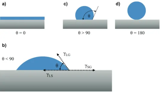
where , , and , are the interfacial tensions between solid/gas (air), solid/liquid, and liquid/gas, respectively. Subscripts are frequently dropped for the fluid/fluid interfacial tension ( ). Eqn. 1.3 describes the force balance at the triple line (between gas, liquid, and solid, c.f. Figure 1.3b) which needs to be satisfied in order to obtain static conditions. For very strong liquid–solid affinity complete wetting or spreading occurs, which represents the limit of the contact angle 0 (Figure 1.3a). For surface angles smaller than 90° the liquid has a high wettability (Figure 1.3b), while for contact angles larger than 90° the liquid has a low wettability (Figure 1.3c). For very weak liquid–solid affinity, complete non–wetting or repulsion occurs, which is represented by a contact angle of 180° (Figure 1.3d).
Figure 1.3: Idealized examples of contact angle and spreading of a liquid (blue) on a flat, smooth solid (gray). Different wetting states are shown: (a) complete wetting or spreading, (b) high wettability, (c) low wettability, and (d) complete non–wetting (repulsion).
8 Chapter 1: Introduction
If water shows a strong affinity towards the solid surface ( < 90°) the solid is said to be hydrophilic, otherwise ( > 90°) it is hydrophobic. However, this terminology typically implies that the second fluid phase is a gas (e.g. air). In general, however, eqn. 1.3 and the definition of the contact angle are also valid if the second fluid is a liquid (e.g. oil). In a system of water, oil and solid, the solid is described as ‘water–wet’ for < 90° and ‘oil–wet’ for > 90°. For contact angles in the range of 80° < < 100° the solid is sometimes described as ‘neutrally–wet’ or ‘intermediate–wet’ [55]. For solid/liquid/gas systems, the contact angle is always measured between the liquid and the solid and therefore unambiguous (c.f. Figure 1.3). Special attention, however, needs to be paid to the definition of the contact angle if the second fluid is a liquid as well. The liquid for which the contact angle measurement applies needs to be clearly stated. In this text the contact angle typically refers to the water phase or an appropriate subscript is introduced.
Capillary pressure, or Laplace pressure, describes a pressure difference across a fluid/fluid interface [56]:
∆ ( 1.4 )
where is the capillary pressure and and are the pressures in non– wetting and wetting phase, respectively (Figure 1.4). The capillary pressure is a result of the surface tension in a curved surface and defined by the Young–Laplace law as [56]:
( 1.5 )
where is the mean curvature of the meniscus. For a spherical meniscus in a cylindrical tube as shown in Figure 1.4, the curvature is given as:
2 2cos
( 1.6 )
1.2 Wettability in Microfluidic Systems 9
Figure 1.4: Capillary rise in a cylindrical tube of radius r. The tube (gray) shown in cross–section is dipped in water (blue). Water is wetting the tube material and a spherical meniscus of radius R is formed.
The shape of fluid interfaces in rectangular microchannels was studied in detail by Lenormand et al. [11] and is shown in Figure 1.5. A completely non–wetting fluid forms a slug and small amounts of wetting fluid remain in the corners. However, it was shown that the mean curvature of the fluid interface can be expressed in good approximation by the two main radii of curvature. For a fluid pair with complete wetting/non–wetting ( = 180°, c.f. Figure 1.5), the curvature is therefore given as [11], [57]:
2 1 1 ( 1.7 )
for a channel of width w and height . For partial wetting, the mean curvature in a rectangular microchannel is given as [58]:
2 cos cos ( 1.8 )
As eqns. 1.5 to 1.8 show, capillary pressure is closely related to wettability through the contact angle.
10 Chapter 1: Introduction
Figure 1.5: Fluid interface in a rectangular microchannel: (a) perspective view, (b) cross–sectional view in the plane P [11].
In microfluidic systems, both for continuous microflows as well as for droplet– based microfluidics, the liquid streams or droplets need to be guided through the system in a controlled fashion [59], [60]. Since the fluid types are typically dictated by the application itself, proper flow guidance needs to rely on channel geometry and surface properties (i.e. wettability) of the microfluidic device. Microfluidc devices are typically made from glass or transparent polymers with various surface properties [61], [62]. For example PDMS, one of the most commonly used polymers for microfluidic applications [63], possesses a hydrophobic surface ( = 108° [64]), and is the material employed in this work. In many cases wettability needs to be modified and tailored to specific needs in order for the devices to provide the desired functionalities [65]. For example, filling of hydrophobic systems with aqueous solutions might be challenging, in particular for small channel geometries, due to
1.2 Wettability in Microfluidic Systems 11
large capillary pressures (eqn. 1.5), and requires homogeneous wettability alterations towards surface hydrophilicity. In the case of droplet–based microfluidics, wettability properties need to be carefully considered as well: stability requirements dictate good wettability between the continuous phase and the channel walls [66], [67]. Other applications require much more sophisticated surface modifications, such as patterned wettability which is a requirement for multiple emulsion encapsulation [68], [69]. A continued, more detailed review and discussion of surface treatment, patterning and functionalization in microfluidic systems for cross–discipline general applications is provided in Chapter 2.
Particular interest of wettability patterning in the present work was focused towards the investigation of multiphase flow in micromodels with patterned wettability. As mentioned previously, despite the urgent need for careful investigations on flow behavior in networks with factional (patterned) wettability, detailed experimental results have remained elusive [42]. The absence of convincing experimental results is mainly due to the lack of technology to pattern wettability in micromodels.
A few approaches were made in recent years to fabricate micromodels with heterogeneous wettability properties. One method consists of packing glass and polymer beads in a single layer between two glass plates [37], [38]. If beads of different wettability are used, heterogeneities can be created; however, control over pore geometry is not possible. In a modified method, glass beads of various sizes were packed in multiple layers to also vary pore space [70], but fluid propagation in multiple layers does not allow for detailed pore–level observations. A different approach was made by using classical micromodels etched and sealed in glass, which provide strongly water–wet surfaces in their native state. Wettability was then altered by aging in either crude oil [71] or with a specific silicate gel [72]. Wettability heterogeneities could be induced by partial filling with the agent, but there was no spatial control over the heterogeneities. All techniques suffer from either poor control over the wettability pattern or poor control over the pore space. One approach as reported by Laroche et al. [73] describes a promising concept: a classical micromodel
12 Chapter 1: Introduction
was etched into glass followed by silanization with octadecyltrichlorosilane (OTS) to provide oil–wet surfaces. OTS could then be selectively etched away by acid to locally recover initial water–wet properties. However wettability patterning needed to be performed on the open halves, which made proper sealing of the system impossible and spatial resolution was limited to coarse patches with centimetric resolution.
It is obvious that progress on this subject of study is limited by lacking technology. The development of a wettability patterning technique of high quality and high spatial resolution applicable within sealed microfluidic devices is required in order to continue progress on multiphase flow studies in micromodels with fractional wettability.
1.3 Wettability in the Oil Industry
Rock wettability is a major factor in oil recovery, controlling the location, flow, and distribution of fluids in a reservoir. Wettability affects most of the petrophysical properties of reservoir rocks including capillary pressure, relative permeability, waterflood behavior, electrical properties, and enhanced oil recovery (EOR). [74], [75], [76]. However, only in recent years has wettability been fully recognized as an important factor, while for most parts of the last century common reservoir engineering practices were based on the assumption that oil reservoirs are homogeneously water–wet [41], [77].
Reservoir rock wettability is generally classified as either homogeneous or heterogeneous. For the homogeneous case the entire rock surface exhibits uniform wettability of a certain type. The rock might be water–wet (Figure 1.6a), oil–wet (Figure 1.6c) or at some intermediate wettability state [41], [55], [78]. On the other hand, for the heterogeneous case, different, distinguishable surface regions within the rock exhibit different wettability. Two different types of heterogeneous wetting states are commonly recognized [36]: fractional wettability and mixed wettability. Fractional wettability (Figure 1.6b) provides a generalized definition and is typically used to describe random wettability distribution from single pore scale to clusters of
1.3 Wettability in the Oil Industry 13
pores [79]. Mixed wettability describes a particular case where a network of large pores exhibits oil–wet surfaces while small pores are water–wet [80]. The notion of this very specific definition of mixed wettability is based on a particular mechanism for this pattern to form in oil reservoirs as discussed below. In some literature, fractional wettability is further distinguished and labeled, for example as dalmatian1 or speckled2 wettability, based on other distinct patterns [81].
Figure 1.6: Wetting in pores [82].
Reservoir rocks are complex structures comprised of a variety of different minerals, where each mineral might have a different wettability [82]. In addition, the surface wettability can be altered by adsorption of polar compounds or film deposition of organic material [55], [81], [83], [84]. Most of the pure minerals present in reservoir rock are hydrophilic, which would make a clean rock strongly water–wet [85]. For this reason all oil reservoirs were assumed to be water–wet in the past. However, wettability is oftentimes permanently altered by adsorption or deposition of organic material present in the crude oil [55], [86], [87]. Typically, the wettability altering molecules are contained within the heavy fraction of the crude oil, the asphaltenes [88], [89]. Mechanisms of wettability alteration by crude oils strongly
1 Water-wet and oil-wet surfaces both distributed as discontinuous patches. 2 Patches of oil-wet areas within a continuous water-wet surface.
14 Chapter 1: Introduction
depend on oil composition, rock and mineral type, as well as on the water (brine) properties [81], [90]. Water is present in a reservoir in the form of brine at a certain salinity and various levels of acidity or alkalinity. The stability of residual water films is a critical factor in allowing or preventing asphaltene molecules from the oil phase to reach and adhere to the mineral surface and thereby alter the rock wettability [91], [92]. It is also evident that mineral composition of the reservoir rock promotes or prevents such wettability alterations. While a large number of silicate reservoirs (e.g. sandstone) are believed to be water–wet, most of the carbonate reservoirs are oil–wet or mix–wet [55], [39], [81].
Oil reservoirs evolve by oil migration into initially brine–filled pore space of naturally water–wet rock [41]. Oil as the non–wetting phase preferentially invades the large pores, leaving water in the small pores and as a film along the mineral surface. Depending on rock surface roughness and brine composition, residual water films in the large pores might collapse, allowing for direct oil/rock contact, which alters the local rock wettability permanently [93]. At the same time, water remains in the small pores and sharp corners and prevents direct oil/rock contact hence retaining initial water–wet conditions. Such mechanisms lead to the development of fractional or mixed wettability in oil reservoirs [41], [80], [36].
Detailed knowledge of reservoir wettability conditions is crucial for the development of optimal production strategies. However, proper wettability assessment is challenging and definitive conclusions frequently remain elusive, particularly in the case of heterogeneous wettability [42], [90]. Reservoir wettability is determined from laboratory analysis of core samples [94]. Extracting a core and providing samples to the laboratory in pristine conditions is not an easy task and can often generate significant alterations to the core sample. Wettability alterations of the core samples from their reservoir state during cutting, surfacing and subsequent handling can occur for a number of reasons such as drilling fluid contamination, oxidation, drying and, most importantly, temperature and pressure reduction effects on crude oil composition such as asphaltene precipitation or wax deposition [77], [88]. Several methods are available to measure wettability in core samples based on
1.3 Wettability in the Oil Industry 15
contact angle or capillary pressure measurements [94], [95]. Measurements based on capillary pressure employ imbibition and drainage cycles to gauge the bulk wettability of the sample and provide a wettability index ranking between water–wet and oil–wet. Such methods provide sound results for homogeneous wettability but heterogeneous wettability conditions cannot be identified and are indistinguishable from intermediate homogeneous wettability [95]. Contact angle measurements, such as the sessile drop technique, are challenging to apply on rough, porous surfaces and the validity of the wetting state of the freshly cut rock surface is questionable. A continued and more detailed review and discussion of wettability measurements in core samples is provided in Chapter 3.
Extraction and recovery of crude oil from a reservoir can be classified in three main stages: primary, secondary, and tertiary recovery. During primary recovery typically 5 – 15% of the original oil in place is produced by the overburden pressure through the oil wells drilled into the reservoir. Another 15 – 30% of oil can be produced by forced water injection, known as water flooding or secondary recovery [96], [97]. A variety of additional techniques, generally referred to as enhanced oil recovery (EOR) or tertiary recovery, can be employed to extract another 5 – 15%, yielding an overall recovery of 30 – 60% of the original oil in place [93], [97]. Such techniques aim for the recovery of oil retained by to capillary forces or immobilized due to high viscosity and include injection of miscible fluids, chemical floods, surfactant or polymer injection, steam injection, etc. [98], [99].
Precise knowledge of reservoir wettability is essential for accurate predictions of several factors, such as residual oil saturation or relative permeability, which in turn are major factors for economic evaluations during waterflooding and EOR [100], [101]. Water flooding is a common practice in oil recovery and has been employed for many years [102], [103]. Figure 1.7 shows the principle of a typical waterflood operation.
16 Chapter 1: Introduction
Figure 1.7: Secondary oil recovery by waterflooding: the displacing fluid (water) is injected in to the reservoir through the injector well (right) and displaced oil is recovered at the production well (left) [104].
During waterflooding of a water–wet reservoir, water advances through the porous medium in a fairly flat front [105]. Despite a fairly uniform water front on a macro–scale, a considerable oil fraction is trapped due to entrapment mechanisms on the micro–scale [106]. Figure 1.8a shows an example of oil entrapment by a snap–off mechanism where water as the wetting phase can advance as surface films while oil still remains in the center of large pores [107]. For large aspect ratios, where a wide pore is connected through very small throats, water films in the throats frequently coalesce and cut off globules of oil from the continuous oil phase. Since oil is the non–wetting phase (large contact angles oil) the large pressure required to overcome
the capillary pressure (eqn. 1.4) and move the oil globules through the narrow throats effectively traps the disconnected oil in the large pores [105], [108], [109]. After the water front passes almost all the remaining oil is immobile. Due to this immobilization in the water–wet case there is little or no oil production after water breakthrough at the production well, and waterflooding can be stopped [40]. Figure
1.3 Wettability in the Oil Industry 17
1.9 shows oil recovery as a function of injected water volume for a laboratory experiment on a core sample (solid curve) [107]. Oil recovery ceases shortly after water breakthrough, which occurs at slightly less than one times the pore volume of injected water.
Figure 1.8: Water displacing oil from a pore in (a) a strongly water–wet rock, and (b) a strongly oil–wet rock [107].
18 Chapter 1: Introduction
Figure 1.9: Typical waterflood performance in water–wet and oil–wet sandstone cores at moderate oil/water viscosity ratios [107].
In the case of waterflooding in an oil–wet reservoir, on the other hand, the rock preferentially remains in contact with the oil and waterflooding in this case is much less efficient [40]. The advancing water develops large fingers and invades only a network of larger pores, while oils remains in smaller pores and as a film along the rock surfaces of the large pores (Figure 1.8b). Water breakthrough at the production well occurs quickly with much less water volume injected than in the water–wet case. As water injection continues, more oil is recovered as water continues to invade more pores and additional continuous channels are formed. Residual oil remains connected through continuous films and can therefore continuously be produced; however, recovery rate falls to very low levels when water has formed enough continuous channels in order to flow nearly unrestricted [105], [40]. A waterflood experiment on an oil–wet core sample shows this early water breakthrough with continued oil recovery during injection of many pore volumes of water (Figure 1.9, dashed curve) [107]. A water flood in an oil–wet reservoir is less efficient compared to a water–wet reservoir since many pore volumes of water need to be injected over a significant period of time, and during flooding large amounts of water are produced together with oil in the production well. Additional complications and decrease in efficiency can
1.4 Outline 19
occur in fractured reservoirs. It is believed that during flooding, water mainly flows in the fractures along the path of least resistance and efficient oil recovery occurs only if water spontaneously imbibes into the matrix blocks and thereby displaces the oil into the network of fractures [110], [111], [112]. Spontaneous imbibition of water, however, can only occur in water–wet rock.
In the case of fractional wettability, it was experimentally shown that waterflood efficiency drops with increasing oil–wet fraction [40], [113], [114]. However, for the particular case of mixed wettability, waterflooding is consistently reported to be very efficient and yield residual oil saturations much lower than for the water–water case [15], [42], [80], [115]. The particular configuration of the mixed–wet state, with a continuous oil–wet surface along the large pores and water–wet small pores, combines the advantages of both oil–wet and water–wet mechanisms. Water easily invades the porous medium due to the water–wet surface areas, however, snap–off mechanisms typical for water–wet rock (c.f. Figure 1.8a) are largely eliminated since oil can continuously be drained through surface films along the oil–wet surfaces [40].
The significance of the reservoir wettability state is evident from the discussion on secondary recovery (waterflooding) and it plays an equally important role for fluid injection during tertiary recovery (EOR) [116]. In particular, heterogeneous wettability, which can have the highest impact (e.g. on waterflooding), is the least understood wettability class. Detailed knowledge of the rock wettability is key, yet often remains elusive [42], [90]. A lack in appropriate wettability measurement techniques is apparent; new methods and tools for reservoir wettability assessment are needed.
1.4 Outline
The present study focuses on wettability effects in porous media and their influence on multiphase flow behavior with a particular focus on applications for the petroleum industry.
20 Chapter 1: Introduction
Chapter 2 is dedicated to studies on micromodels. A large part of the work was focused on the technological progress required to fabricate micromodels with well controlled wettability patterns. Micromodels were fabricated in PDMS by soft lithography, which is reviewed in section 2.1. Surface treatment in these systems was achieved by selective graft photo–polymerization, which presents a key technology required for wettability patterning in micromodels. The surface treatment technique is presented in section 2.2. A study of multiphase flow behavior in micromodels of patterned wettability is presented in section 2.3. Further applications of the wettability patterning technique are also outlined.
Chapter 3 is dedicated to applications for the oil industry. A new wettability measurement technique for rock samples based on visual imaging is investigated in section 3.1. The measurement technique is based on flow regime predictions established by studies on micromodels. A novel instrument for microscopic imaging of rock samples is presented in section 3.2 and characterized in detail. This imager instrument allows for multiphase fluid observations on the pore level of a rock and might become a new tool for wettability assessment.
Chapter 2
Wettability Patterning in PDMS
The field of microfluidics has made significant progress and experienced great success during the last three decades [117], [118], although the field is still at an early stage of development [119]. Microfluidics has great impact across many disciplines such as chemistry, biology, and live science [120], [121], [122], [123], [124], and also in fluid mechanics and physics [125], [126], [127], both for applications [128] as well as for fundamental research. Microfluidic systems are typically made from various materials such as glass or silicon but polymers have become increasingly popular [61] due to their significantly lower costs, les complicated and faster fabrication, as well as their unique chemical, structural and biological functionalities [62]. In particular PDMS is a popular material widely used for microfluidic applications [129], [130], [131]. A detailed review of PDMS microfluidic systems and their fabrication is given in section 2.1.
In many cases the material properties of the host microfluidic devices are not sufficient and applications require modified surface properties and functionalized surfaces, carefully tailored to the task at hand [132], [133]. For example, systems made of hydrophobic PDMS frequently require surface modifications of the microfluidic channel in order to obtain hydrophilic surface properties. Several different techniques for surface modifications are available [134], [135]: oxygen plasma treatment and adsorbed surfactant coatings have been proven to work well for certain types of applications but suffer from a lack of long–term stability [136], [64]. Alternatively, covalent surface modifications such as self–assembled monolayers, or surface grafted polymer chains, provide much better long–term stability [136], [137].
22 Chapter 2: Wettability Patterning in PDMS
In particular, surface modification by grafting of functional polymers is a versatile and powerful tool, which allows for careful tailoring of the desired surface properties [138]. A number of different surface grafting techniques exist for liquid or vapor phase systems with graft polymerization initiation by plasma discharge, oxidation through ozone, UV initiation, etc. [139], [140]. In particular, UV–induced surface graft polymerization is widely applied to modify open surfaces [141] such as polymer sheets or membranes [142], [143]. Treatments within enclosed microfluidic structures, on the other hand, pose significant challenges and suffer in many cases from low yield and poor quality [144], [145]. In addition, many applications require the ability to pattern surface properties: the surface modifications need to be applied locally with high spatial control while maintaining high surface quality of both original and patterned parts [146].
Surface–directed UV–initiated graft polymerization is a technique well suited to pattern functionalized polymers within microfluidic structures enclosed in PDMS at high spatial resolution. This technique is presented in detail in section 2.2. Applications for this wettability patterning technique are presented and discussed in section 2.3.
2.1 Microfluidic Systems Made of PDMS
PDMS is one of the most widely used polymers for fabrication of microfluidic systems [62]. The use of a PDMS elastomer for microfluidic systems has numerous advantages over silicone or glass. Systems made of PDMS can be easily and quickly fabricated at low cost by rapid prototyping techniques such as soft lithography [147], [148], and when PDMS is cast from a mold it replicates the features of the master with high fidelity (tens of nanometers) [63]. PDMS is optically transparent over a wide wavelength range down to UVB (280 nm) [129] and therefore compatible with many optical detection methods. It is also a non–toxic, biocompatible material which is impermeable to water and permeable to gases [131], [149]. Furthermore, PDMS provides a hydrophobic surface with a water contact angle of 108° in air [64].
2.1 Microfluidic Systems Made of PDMS 23
The PDMS cast containing the microstructures can readily form a reversible seal with a plane counterpart (e.g. flat sheet of PDMS) due to van der Waals forces [63]. Irreversible seals with significantly higher bonding strengths can also easily be realized by bonding due to plasma oxidation of the surface [64] or by an alternative technique with partial pre–curing, bonding, and post–curing of two PDMS halves [150].
A detailed description of the fabrication process for PDMS microfluidic devices, as employed in this research, is presented in the following sub–sections.
2.1.1 Fabrication of Microfluidic Systems
The general process of the fabrication of a PDMS microfluidic device by soft lithography is shown in Figure 2.1. In short, a photolithographic process is used to transfer the desired structure to a photoresist deposited on a silicon waver in order to create a silicon master (Figure 2.1a). PDMS devices are then cast from the master by pouring liquid PDMS prepolymer onto the master and allowing for curing at elevated temperatures (Figure 2.1b). The cured, solidified PDMS is then peeled off from the master and bonded to a flat counterpart in order form an enclosed microfluidic system (Figure 2.1c). The silicon master can be reused and any number of PDMS devices can be produced in a fast and easy way by repetition of the final two stages.
A detailed description of the process is given below, including a description of the materials and methods used in the present work.
24 Chapter 2: Wettability Patterning in PDMS
Figure 2.1: General process of PDMS device fabrication. (a) Fabrication of silicon master: Desired structures are transferred to photoresist on silicon waver via photolithography. (b) Cast from the silicone master transfers the embossed master structures as grooves to the PDMS device. (c) PDMS device is bonded against a flat counterpart in order to create enclosed microfluidic structures [151].
2.1.2 Fabrication of Silicon Master
As mentioned in the previous sub–section, the first step in making a new microfluidic device is the fabrication of a silicon master by photolithography (c.f. Figure 2.1a). A schematic of the fabrication process is shown in Figure 2.2. In a first step, the photoresist SU83 was spun on a pre–cleaned silicon wafer on a spin coater
and a soft bake was performed according to the manufacturer’s specifications [152] in order to remove the solvent. By variation of SU8 solvent content (viscosity) and spinning speed the desired film thickness of the photoresist could be achieved (Figure
2.1 Microfluidic Systems Made of PDMS 25
2.2a). Typically, film thicknesses from 0.5 µm to 200 µm and more can be achieved in a single coating [152].
Figure 2.2: Silicon master fabrication process. (a) SU8 photoresist is spun onto a silicon waver at a desired thickness. (b) Microstructures are transferred to the photoresist by UV exposure through a mask. (c) Developed photoresist provides the microfluidic structures on the silicon master.
The desired microstructures were transferred to the photoresist by UV exposure on a mask–aligner4 at at wavelentgh of 365 nm (Figure 2.2b). The applied UV energy dose was determined as a function of the photoresist thickness according to the manufacturer’s specifications [152]. After exposure the waver was subjected to a post–bake in order to allow for cross–linking in the exposed SU8 areas followed by a developing step, where non–exposed SU8 was removed by the developer solvent (Figure 2.2c). An optional hard bake [152] was typically performed as well in order to further increase the durability of the master. Final dimensions of the fabricated structures were verified with a mechanical needle profiler5.
The structures of the microfluidic system were custom–designed with CAD software and corresponding masks were obtained, either as ink–printed foil masks or etched chrome masks on glass substrate. The resolution of the foil masks was limited
4 MJB4 mask-aligner, Süss MicroTec AG, Garching, Germany.
26 Chapter 2: Wettability Patterning in PDMS
by the printer to 3600 dpi (7 µm per dot) while chrome masks provided nanometric resolution. However, if resolution was not critical, foil masks were chosen by default since they were faster to produce at significantly lower cost.
2.1.3 Fabrication of PDMS Devices
The fabrication of the PDMS chip itself consists in casting a PDMS slab from the silicone master and bonding it against a second, flat PDMS slab (c.f. Figure 2.1b–c). A schematic representation of the process is shown in Figure 2.3. First, PDMS pre– polymer6 was prepared for casting: a PDMS base (linear polymer chains) was thoroughly mixed with curing agent (cross–linker) at a ratio of 10:1 (w/w) and poured onto the silicon master placed in a disposable Petri dish (Figure 2.3a). The cast was allowed to cure in an oven at 65°C for 2 hours before it was peeled from the silicon master. The PDMS slab containing the impression of the microfluidic structure was then cut to size and via holes were punched into the slab in order to provide chip–to– world fluid connections in the final device (Figure 2.3b).
Figure 2.3: Fabrication of microfluidic PDMS chip. (a) PDMS pre– polymer is poured onto the silicon master and allowed to cure. (b) The cured PDMS slab is peeled off from the silicon master and via holes are created. (c) The micro–structured PDMS half is bonded against a flat substrate (e.g. PDMS) to seal the microfluidic structures.
6 Sylgard 184 Silicone Elastomer Kit (Base and Curing Agent), Dow Corning Corporation,
2.2 Surface Treatment in Microfluidic Systems 27
In parallel, a flat PDMS slab was prepared by casting from a flat surface (disposable Petri dish) and following the same protocol. Both halves were then bonded against each other in order to produce a device with enclosed microfluidic structures (Figure 2.3c). Bonding was achieved by activating the surfaces of the two halves in oxygen plasma7 for 30 seconds at 400 mTorr and a power of 30 W applied to the RF–coil. After the plasma treatment both halves were immediately brought in contact in order to allow for irreversible bonds to form, which sealed the device permanently. The devices were then typically annealed in an oven at 90°C for two days in order to reverse the plasma–induced surface changes and recover the native water contact angle of PDMS of 108° [153].
2.2 Surface Treatment in Microfluidic Systems
Covalent polymer coatings are oftentimes superior to other surface modification methods in terms of mechanical and chemical robustness and also provide a high degree of flexibility towards the introduction of a variety of functional groups [154]. These covalent polymer coating techniques can be classified in two categories: (1) “grafting–to”, where end–functionalized polymers are covalently tethered onto the target surface, and (2) “grafting–from”, where polymerization of monomers is initiated on the target surface and polymer brushes are grown [136]. While both techniques are commonly used for modifications on open surfaces, application within enclosed capillaries and microfluidic channels is extremely challenging, in part due to the problem of bulk polymerization and subsequent clogging of the channels during treatment. The “grafting–from” technique is favorable since only small monomers need to be introduced into the micro–channels. Following work related to PAA grafting on open PDMS surfaces [155], [156], [157], the first success of graft polymerization of PAA within simple micro–channels was reported by the same group in 2004 [158]. However, many parameters for the surface treatment were neglected, overlooked, or misinterpreted, which caused the treatments in many cases to be unreliable and of low quality, and significant improvements were required.
28 Chapter 2: Wettability Patterning in PDMS
Based on this obvious need, a significant part of the present work was dedicated to a careful study of surface treatments in order to provide a reliable protocol yielding high quality surface patterning.
In the next section (2.2.1), a detailed study on surface treatment for wettability patterning within enclosed PDMS microfluidic structures is presented and discussed. The specific method employed is surface–directed UV–initiated graft polymerization of PAA on PDMS, based on a two–step protocol published by Hu et al. [158]. Significant improvements have been made which allow for reliable wettability pattering of high quality at high spatial resolution, which is applicable even in complex microfluidic networks. A brief outline of the process is given below.
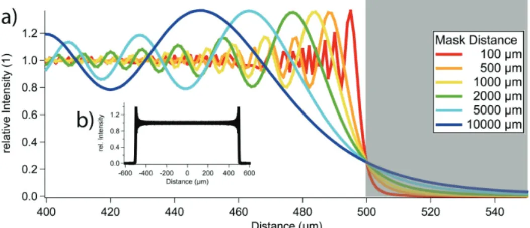
The surface treatment consists of the two main steps: priming and graft polymerization. Figure 2.4 shows the treatment process on a schematic cross–section of a single channel (white) in a PDMS chip (blue). The priming step serves to deposit BP photoinitiator along the PDMS walls. Therefore, a solution of BP in acetone (red) is injected into the microsystem8 as shown in Figure 2.4b. During photoinitiator injection BP molecules diffuse into the PDMS matrix and form a reservoir of photoinitiator in proximity to the channel walls, even after the solution is removed (shown as light red in Figure 2.4c). In a second step, the channel is filled with an aqueous solution of AA monomers9 (shown as green in Figure 2.4d) and the system is exposed to UV light 10 (Figure 2.4e). During UV exposure, BP molecules are excited, and relax by hydrogen abstraction typically from the PDMS methyl groups thus creating free radical sites. From these free radical sites, AA starts to polymerize and PAA grows on and within the PDMS walls. After cleaning, a covalently tethered PAA coating remains along the channel walls (dark green) as shown in Figure 2.4e. In contrast to native, hydrophobic PDMS, the PAA coating is strongly hydrophilic, providing a large contrast in wettability (surface energy). The two–step protocol ensures that photoinitiator and monomers are in contact only along the walls where
8 Solution of 10 wt% BP in acetone injected for typically 5 min. 9 Typically 20 wt% AA in pure water, for more details see section 2.2.1. 10 UV exposure at 365 nm for typically 5 min at 35-50 mW/cm2.
2.2 Surface Treatment in Microfluidic Systems 29
surface treatment is desired, hence reducing or eliminating interfering bulk polymerization within the channel.
Figure 2.4: Schematic treatment process for surface–directed UV–initiated graft polymerization of PAA on PDMS surfaces. A cross–section of a single channel in PDMS (blue) is shown. First, during priming, BP solution (red) is injected and BP is allowed to diffuse into PDMS walls (light red). In a second step, AA monomer solution (green) is filled into the channel and exposed to UV light, which yield a coating of grafted PAA (dark green).
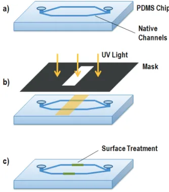
Patterning of the treatment can easily be realized by selective UV exposure through a mask as shown in Figure 2.5: a schematic PDMS chip with multiple channels is depicted in Figure 2.5a. After priming and filling the channels with monomer solution (c.f. Figure 2.4) certain areas can then be selectively exposed to UV light through a mask (Figure 2.5b). Treatment is only applied in the exposed segments hence providing a microfluidic system with patterned surface properties (Figure 2.5c).
30 Chapter 2: Wettability Patterning in PDMS
Figure 2.5: Schematic of the patterning process. (a) A microfluidic device is prepared for surface treatment (primed with BP and filled with AA monomer solution). (b) Graft initiation is selectively initiated by UV exposure through a mask. (c) The final system contains a patterned surface treatment as defined by the mask.
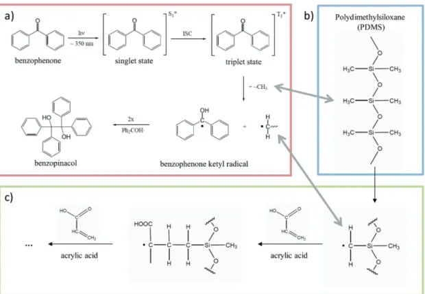
The photochemical process during UV exposure is schematically shown in Figure 2.6. The predominant reaction scheme for the photoinitiator BP is outlined11 in Figure 2.6a. UV radiation excites BP and quickly produces triplet BP. If in proximity to a hydrogen donor site, triplet BP is relaxed via hydrogen abstraction to BP ketyl radical, thus forming a free radical at the donor site. BP ketyl radicals typically combine with each other to form benzopinacol. Within the PDMS matrix, methyl groups are favorable donor sites for hydrogen abstraction (Figure 2.6b). After radicalization, PAA starts to grow from the PDMS chain as illustrated in (Figure 2.6c).
11 For details see Appendix A.
2.2 Surface Treatment in Microfluidic Systems 31
Figure 2.6: Schematic outline of the photochemical process involved in surface treatment showing (a) BP photoinitiation, (b) PDMS, and (c) PAA graft polymerization.
Significant effort was dedicated to the investigation of the priming process itself. In particular the diffusion properties of BP within PDMS were studied in detail, a critical factor for successful surface treatment which seems to have been neglected in literature so far. The results, surprisingly fast BP migration in acetone–swollen PDMS together with a new in–situ visualization technique, will be published in Langmuir as presented in Appendix A.
The entire surface treatment process was carefully studied as well and every step of the treatment process was rigorously investigated in order to identify the key parameters required to perform a stable and reliable treatment of high quality. The influence of each parameter was carefully investigated and recommended values were identified. This detailed understanding of the treatment process and the effects of the critical parameters on it allowed for significant improvements in quality and
32 Chapter 2: Wettability Patterning in PDMS
reliability of the process. These new results and the deepened understanding of a significantly improved surface–directed UV–initiated graft polymerization process, together with a ‘recipe’ of detailed step–by–step instructions, were published in Analytical Chemistry in order to make them available to the field. The full article is presented in the following section.
2.2.1 Article: Wettability Patterning by UV–Initiated Graft
Polymerization of Poly(acrylic acid) in Closed
Wettability Patterning by UV-Initiated Graft
Polymerization of Poly(acrylic acid) in Closed
Microfluidic Systems of Complex Geometry
Marc H. Schneider,*,†,‡Herve´ Willaime,†Yvette Tran,†Fadhel Rezgui,‡and Patrick Tabeling† ESPCI, 10 Rue Vauquelin, 75005 Paris, France, and Schlumberger, 1 Rue Henri Becquerel, 92140 Clamart, France
嘷w This paper contains enhanced objects available on
the Internet at http://pubs.acs.org/ac.
Many microfluidic applications require modified surface wettability of the microchannels. Patterning of wettability within enclosed microfluidic structures at high spatial resolution has been challenging in the past. In this paper, we report an improved method for altering the surface wettability in poly(dimethylsiloxane) (PDMS) microchan-nels by UV-induced graft polymerization of poly(acrylic acid). Our method presents significant improvements in terms of wettability contrast and spatial resolution of the patterned structures as compared to recent literature and is in particular applicable to complex microfluidic struc-tures with a broad range of channel sizes and aspect ratios. A key part of our work is the clear description of the surface treatment process with the identification of key parameters, some of which have been overlooked, neglected, or misinterpreted in previous works. We have studied these key parameters in detail and provide recommended values for each parameter supported by experimental results. This detailed understanding of the treatment process and the effects of the critical parameters on it allowed us to significantly improve quality and reliability of the treatment process.
Microfluidic devices made with rapid prototyping techniques, especially soft lithography,1 have given rise to an enormous amount and versatility of applications across many fields. A favorite material frequently used for such devices is poly(dimethylsilox-ane) (PDMS), which provides a number of advantageous proper-ties such as its flexibility, durability, transparency, and chemical inertness to name a few. Casting PDMS from a mold and subsequent bonding to a flat PDMS counterpart provides a very rapid fabrication method for enclosed microfluidic devices,2,3 which can provide elaborate channel structures of varying depth.
For many applications, PDMS devices in their native, hydrophobic state are readily utilizable and well suited for the particular task. Other applications, however, demand different surface properties such as hydrophilic walls, e.g., in order to facilitate the filling of such devices with aqueous solutions.4Common hydrophilization techniques include oxygen plasma treatment4 and adsorbed surfactant coatings, and both techniques have been proven to work well for certain types of applications but suffer frequently from a lack of long-term stability2and might not be practical if a patterned treatment is required.5 A widely used surface modification technique in polymer science is the surface-attached polymeriza-tion, which provides chemically stable surfaces due to the covalent attachment of the polymer chains to the substrate.4,6-9 Such surface modification can be initiated by a number of different techniques,6e.g., plasma discharge, oxidation through ozone,10 and UV irradiation,11which can be applied either to liquid phase systems or vapor phase systems.9,5Since plasma discharge and ozone methods typically start the initialization on all accessible surfaces, patterned surface modifications can be achieved only by partially covering the substrate surface. In contrast, the UV irradiation method has the inherent advantage that polymerization is only initiated in areas exposed to UV light, which is a well suited method if spatially patterned surface modifications are required. In 2002, the first successful grafting of poly(acrylic acid) (PAA) on PDMS based on a liquid phase system with UV irradiation was reported by Hu et al.,12which was previously used for surface modifications on poly(ethylene) substrates.13This early protocol was based on a one-step process with long, intensive UV exposure of open PDMS systems in order to directly initialize polymerization on the surface. After several improvements,14,15the first success of graft polymerization of PAA in closed PDMS channels was
* To whom correspondence should be addressed. E-mail: [email protected].
†ESPCI. ‡Schlumberger.
(1) Xia, Y.; Whitesides, G. M. Annu. Rev. Mater. Sci. 1998, 28, 153–184. (2) Duffy, D. C.; McDonald, J. C.; Schueller, O. J. A.; Whitesides, G. M. Anal.
Chem.1998, 70, 4974–4984.
(3) McDonald, J. C.; Duffy, D. C.; Anderson, J. R.; Chiu, D. T.; Wu, H.; Schueller, O. J. A.; Whitesides, G. M. Electrophoresis 2000, 21, 27–40.
(4) Liu, J.; Lee, M. L. Electrophoresis 2006, 27, 3533–3546.
(5) Wong, I.; Ho, C.-M. Microfluid. Nanofluid. 2009, 7, 291–306.
(6) Kato, K.; Uchida, E.; Kang, E.-T.; Uyama, Y.; Ikada, Y. Prog. Polym. Sci.
2003, 28, 209–259.
(7) He, D.; Susanto, H.; Ulbricht, M. Prog. Polym. Sci. 2008, 34, 62–98.
(8) Nie, Z.; Kumacheva, E. Nat. Mater. 2008, 7, 277–290.
(9) Deng, J.; Wang, L.; Liu, L.; Yang, W. Prog. Polym. Sci. 2009, 34, 156–193.
(10) Diaz-Quijada, G. A.; Wayner, D. D. M. Langmuir 2004, 20, 9607–9611.
(11) Uyama, Y.; Kato, K.; Ikada, Y. Surface Modification of Polymers by Grafting; Springer Verlag: Heidelberg, Germany, 1998; Vol. 137, pp 1-39. (12) Hu, S.; Ren, X.; Bachman, M.; Sims, C. E.; Li, G. P.; Allbritton, N. Anal.
Chem.2002, 74, 4117–4123.
(13) Richey, T.; Iwata, H.; Oowaki, H.; Uchida, E.; Matsuda, S.; Ikada, Y. Biomaterials2000, 21, 1057–1065.
(14) Hu, S.; Ren, X.; Bachman, M.; Sims, C. E.; Li, G. P.; Allbritton, N. Electrophoresis2003, 24, 3679–3688.
(15) Hu, S.; Ren, X.; Bachman, M.; Sims, C. E.; Li, G. P.; Allbritton, N. Langmuir
2004, 20, 5569–5574.
Anal. Chem. 2010, 82, 8848–8855
10.1021/ac101345m© 2010 American Chemical Society
8848 Analytical Chemistry, Vol. 82, No. 21, November 1, 2010
![Figure 1.2: Phase diagrams for imbibition: left–hand figure, large aspect ratio; right–hand figure, small aspect ratio [21]](https://thumb-eu.123doks.com/thumbv2/123doknet/2904531.75112/13.892.183.692.156.582/figure-phase-diagrams-imbibition-figure-aspect-figure-aspect.webp)
![Figure 1.9: Typical waterflood performance in water–wet and oil–wet sandstone cores at moderate oil/water viscosity ratios [107]](https://thumb-eu.123doks.com/thumbv2/123doknet/2904531.75112/25.892.217.622.162.454/figure-typical-waterflood-performance-sandstone-moderate-viscosity-ratios.webp)