HAL Id: tel-02133961
https://pastel.archives-ouvertes.fr/tel-02133961
Submitted on 20 May 2019
HAL is a multi-disciplinary open access archive for the deposit and dissemination of sci-entific research documents, whether they are pub-lished or not. The documents may come from teaching and research institutions in France or abroad, or from public or private research centers.
L’archive ouverte pluridisciplinaire HAL, est destinée au dépôt et à la diffusion de documents scientifiques de niveau recherche, publiés ou non, émanant des établissements d’enseignement et de recherche français ou étrangers, des laboratoires publics ou privés.
centimeter–and–millimeter–wave frequencies in 5G
urban micro–cellular context
Cheikh Diakhate
To cite this version:
Cheikh Diakhate. Propagation channel modeling at centimeter–and–millimeter–wave frequencies in 5G urban micro–cellular context. Networking and Internet Architecture [cs.NI]. Université Paris-Saclay, 2019. English. �NNT : 2019SACLT017�. �tel-02133961�
Propagation Channel Modeling at
Centimeter–and–Millimeter–Wave
Frequencies in 5G Urban Micro–cell
Context
.
Thèse de doctorat de l'Université Paris-Saclay
préparée à Télécom ParisTech
École doctorale n°580 Sciences et Technologies de l’Information et
de la Communication (STIC)
Spécialité de doctorat: Réseaux, Information et Communications
Thèse présentée et soutenue à Paris, le 28 Mars 2019, par
Cheikh A. L. DIAKHATE
Composition du Jury : Hélène ROUSSEL
Professeur, Université Sorbonne Présidente
Bernard UGUEN
Professeur, IETR Rapporteur
Davy GAILLOT
Maître de conférences, TELICE Rapporteur
Alain SIBILLE
Professeur, Télécom ParisTech Directeur de thèse
Jean–Christophe COUSIN
Maître de conférences, Télécom ParisTech Co–Directeur de thèse
Jean–Marc CONRAT
Ingénieur R&D, Orange Labs Co–Encadrant
NNT
:
2
0
1
9
S
A
CL
T
0
17
“We should consider every day lost on which we have not danced at least once.”
Friedrich Nietzsche, “Thus Spoke Zarathustra”.
Acknowledgements
Most definitely my favorite part of this dissertation because I get to momentarily part ways with the impartial professional narration… but I will try not to be too flippant about it
To the Orange Labs entity in Belfort, especially the Wireless Engineering and Propagation (WEP) team which hosted this Ph.D. thesis, a profound acknowledgement to every individual for their contribution to my integration and well–being and to all the accomplishments along the way.
A special thank you to our team manager Daniel Milli, for his understanding and his availability, and, especially, to my supervisor Jean–Marc Conrat for his continued support and his highly relevant feedbacks on this work throughout these three years. The same goes for my thesis supervisors at Telecom ParisTech, Jean–Christophe Cousin and Alain Sibille, whose contributions to this work have also been of significant importance.
A sincere acknowledgment to the committee members—the referees Bernard Uguen at IETR and Davy Gaillot at TELICE, and the examiner Hélène Roussel at Paris VI, UPMC—for their acceptance to review this work in detail.
To my latest friends, Cyrille (quiet force, Hahahaa), Hajer, Nada (music connoisseur, Jajajaa!), Yosra, Adoni, Ayoub, Maroua, Marc, Brieuc, Salima, ..., the darts amateurs i.e. Philippe, Christel, Patrick, Imed, …, the coffee regulars i.e. Mounir, Patrice, Philippe, …, my office mates i.e. Stefan, Yohann and Lionel, I am thankful for the wonderful moments we have shared together,
and the show must go on!
To my childhood friends of “Central Side” i.e. Papis Diaboula (twin brother), Karim Ndour, Papa Niane, Khadim Cissé, ..., to my friends of “Kaaatteusss FC” i.e. Jean–Baptiste (those were the days), Fodé, Chérif (mancunian bro), Eugène, Seydina, ..., to my “Thuillier & Enseirb co–pilots” i.e. Abou, Abass, Eddy Jaures—this attempt to make a list is probably my worst idea in the last three years—
thank you all for the memorable laughs and our unterminable debates,
and long may it last
!Finally, to my parents and role models i.e. Diarra Diakhate and Moussa Diakhate, to my sister Bousso (my number one fan) and my brothers i.e. Modou (stay gassing me up!), Maleye (the happy one) and Mouhammed (the main man), I am extremely grateful to have you in my life. Although you did not necessarily grasp the details of what it has been all about, every single one of you actively listened to me rambling over and over about my activities… literally at any time of day or night because, of course, I do not fare well with multiple time zones
I owe it all to you, many thanks
! At last, a big thank you to my other two mothers, Mame Sissokho and Leila Mbengue, my second father Ady Ndiaye and to Baye O. Ndiaye and Ndeye S. Mbengue,I have extremely appreciated your support
.Title: Propagation Channel Modeling at Centimeter–and–Millimeter–Wave Frequencies in 5G Urban Micro–cellular Context.
Keywords: Propagation, Millimeter–Wave, Measurements, 5G, Urban micro–cellular.
Abstract—The advent of bandwidth–demanding mobile applications and services has led to a massive explosion of the network data traffic. In order to alleviate this issue, millimeter–Wave communications systems are a promising technology for future 5G systems thanks to the large amount of bandwidth available in this frequency range. However, in order to take full advantage of this technology, knowledge of the radio propagation channel characteristics in these frequency bands is paramount. Therefore, in this thesis, the objective is to study the frequency–dependence of the propagation channel large scale parameters (LSPs), which describe the main channel characteristics. These LSPs include the building penetration losses, the channel delay spread, the channel azimuth spread and the propagation path–loss. The studies are performed thanks to measurement campaigns conducted in Belfort, in typical 5G deployment scenarios such as outdoor–to–indoor and urban outdoor environments, between 3 and 60 GHz.
Titre : Modélisation du canal de propagation en contexte urbain, petite cellule, dans les fréquences centimétriques et millimétriques pour la 5G.
Mots clés : Propagation, Millimétrique, Mesures, 5G, Urbain petite cellule.
Résumé—L’émergence des nouvelles applications et services mobiles, nécessitant de plus en plus de débits de communications, contribue à une explosion massive du trafic de données au sein du réseau. Pour faire face à ce challenge, les systèmes millimétriques sont une des technologies identifiées pour les futurs réseaux 5G en raison de la bande passante accrue disponible dans cette plage du spectre. Toutefois, pour tirer pleinement profit de tels systèmes, la connaissance des caractéristiques liées à la propagation des ondes radio dans ces bandes de fréquence est primordiale. Ainsi, dans cette thèse, l’attention est portée sur l’évaluation de la dépendance en fréquence des caractéristiques principales du canal de propagation, généralement décrites par les paramètres dits « large scale parameters (LSPs) ». Ceux–ci incluent les pertes de pénétration, l’étalement temporel ou angulaire du canal et l’affaiblissement moyen du canal. Les études sont basées sur des campagnes de mesures réalisées à Belfort, dans des scénarios de déploiement 5G typiques comme la pénétration à l’intérieur des bâtiments et la propagation en milieu urbain extérieur, entre 3 et 60 GHz.
P. 5
Table of Contents
Acronyms ... 8
Introduction ... 13
I. On the Next Generation (5G) Mobile and Wireless Systems ... 16
1. Vision and Requirements for 5G ... 16
1.1. Overview on 5G technology ... 16
1.2. Main 5G requirements ... 18
2. Key enabling technologies for 5G ... 22
2.1. Massive multiple–input multiple–output (MIMO) systems ... 22
2.2. Millimeter–Wave (mm–Wave) communications systems ... 25
2.3. Small–cells network densification ... 27
2.4. Cloud–based radio access network (C–RAN) ... 29
2.5. Network function virtualization (NFV) ... 31
2.6. Full–duplex communications ... 33
2.7. Device–to–device communications ... 34
3. Focus on millimeter–Wave (mm–Wave) technology ... 35
II. Millimeter–Wave Channel Modeling and Characterization for 5G ... 36
1. Review of earlier channel models ... 36
1.1. 3GPP channel models ... 37
1.2. WINNER channel models ... 37
1.3. COST channel models ... 38
1.4. IEEE 802.11ad channel model ... 39
1.5. Shortcomings of early channel models with regards to 5G ... 39
2. Channel modeling for 5G systems ... 40
2.1. METIS channel models ... 41
2.2. MiWEBA channel model ... 42
P. 6
2.4. 3GPP channel models ... 44
2.5. Parallel channel modeling works ... 44
3. Channel measurements for 5G mm–Wave ... 45
3.1. Channel large–scale parameters (LSPs) definition ... 45
3.2. Outdoor–to–indoor (O2I) propagation scenarios ... 47
3.3. Urban outdoor propagation scenarios ... 51
4. Motivations for further studies ... 59
III. Theoretical Characterization of the Wireless Propagation Channel ... 61
1. Geometrical modeling approach ... 61
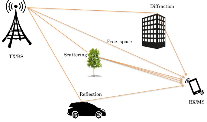
1.1. Multi–path radio propagation channel ... 61
1.2. Geometric channel model ... 62
2. Frequency–dependence of the propagation channel... 64
2.1. Free–space phenomenon ... 65
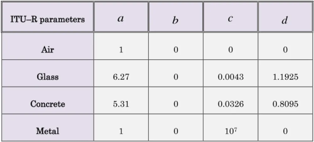
2.2. Reflection and transmission phenomena ... 66
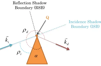
2.3. Diffraction phenomenon ... 76
3. Limitations of the theoretical approach... 81
IV. Outdoor–to–Indoor (O2I) Propagation Channel Measurements ... 83
1. Outdoor–to–Indoor (O2I) measurement campaign ... 83
1.1. Measurement scenario description ... 83
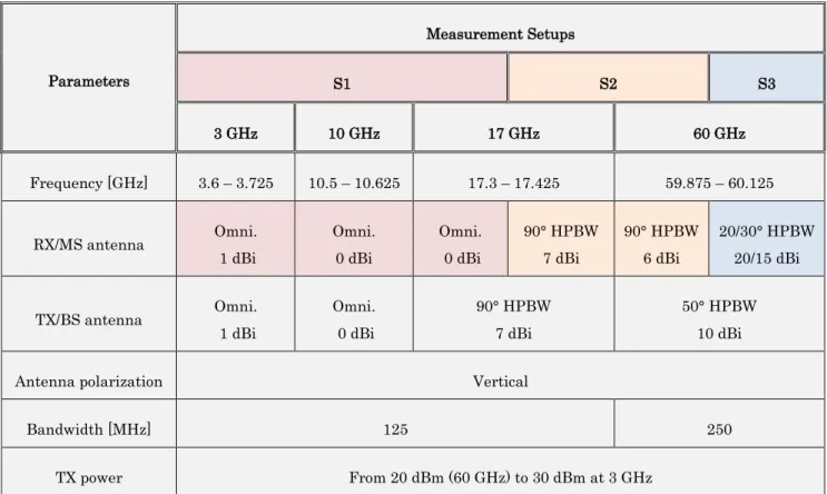
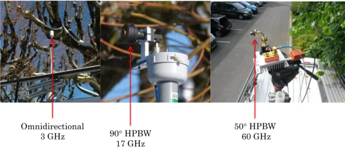
1.2. Measurement setups ... 85
1.3. Measurement procedures ... 88
2. Measurement data processing ... 90
2.1. Data processing for setup S1... 91
2.2. Data processing for setup S2 and setup S3 ... 92
3. Result analysis ... 98
3.1. Measurement validation ... 99
3.2. Building penetration losses (PELs) ... 100
3.3. Channel delay spread (DS) ... 104
4. Summary ... 107
V. Urban Outdoor Propagation Channel Measurements ... 108
1. Urban Outdoor measurement campaign ... 108
P. 7
1.2. Measurement setups ... 109
1.3. Measurement procedure ... 112
2. Measurement data processing ... 112
2.1. Omnidirectional power delay profiles (PDPs) ... 113
2.2. Directional power delay profiles ... 114
2.3. Atmospheric oxygen attenuation ... 114
3. Result analysis ... 116
3.1. Channel delay spread (DS) ... 116
3.2. Azimuth–delay power profile (ADPP) ... 125
3.3. Channel azimuth spread (AS) ... 129
3.4. Propagation path–loss (PL) ... 131
4. Summary ... 133
Conclusion ... 134
A. Channel Measurement Campaigns and Results for 5G ... 138
B. Outdoor–to–Indoor (O2I) Measurement Results in Belfort ... 149
C. Urban Outdoor Measurement Results in Belfort ... 155
1. Delay spread (DS) and azimuth spread (AS) values ... 155
2. Azimuth–delay power profiles (ADPPs) ... 158
Publications ... 229
P. 8
Acronyms
1G : 1st generation ... 13 2–D : Two–Dimensional ... 37 2G : 2nd generation ... 13 3–D : Three–Dimensional ... 38 3G : 3rd generation ... 133GPP : 3rd generation partnership project ... 37
4G : 4th generation ... 14
5G : 5th generation ... 14
ABG : Alpha–Beta–Gamma ... 56
ADPP : Azimuth–Delay Power Profile ... 108
AMPS : Advanced Mobile Phone System ... 13
AR : Augmented Reality ... 17
AS : Azimuth Spread... 45
AWG : Arbitrary Waveform Generator ... 85
BBU : BaseBand Unit ... 30
BR : break–room ... 84
BS : Base Station... 23
CA : Carrier Aggregation ... 14
CAPEX : CAPital EXpenditure ... 31
CDFs : Cumulative Distribution Functions ... 116
P. 9
CIR : Complex Impulse Response ... 45
CN : Core Network ... 33
Co : Corridor ... 84
CoMP : Coordinated Multipoint ... 29
COST : Cooperation in Science and Technology ... 38
C–RAN : Cloud–based Radio Access Network ... 16
CSI : Channel State Information ... 23
D2D : Device–to–Device ... 35
DS : Delay Spread ... 45
DVB : Digital Video Broadcasting ... 13
EBs : Exabytes ... 18
EE : Energy–Efficient ... 45
eICIC : enhanced Inter–Cell Interference Coordination ... 29
eMBB : enhanced Mobile BroadBand ... 16
ETSI : European Telecommunications Standards Institute ... 31
FD : Full–Duplex ... 33
GO : Geometrical Optics ... 66
GSCMs : Geometry–based Stochastic Channel Models ... 38
GSM : Global System for Mobile Communications ... 13
GTD : Geometrical Theory of Diffraction ... 76
HD : Half–Duplex ... 33
HDTV : High Definition TeleVision ... 14
HetNets : Heterogeneous Networks ... 28
HPBW : Half–Power Beam–Width ... 58
P. 10
IEEE : Institute of Electrical and Electronics Engineers ... 39
IoT : Internet of Things ... 17
IRR : InfRaRed ... 49
ISB : Incidence Shadow Boundary ... 79
ITU : International Telecommunications Union ... 16
KED : Knife–Edge Diffraction ... 76
LMDS : Local Multipoint Distribution Service ... 26
LO1 : Large Office 1 ... 84
LO2 : Large Office 2 ... 84
LoS : Line–of–Sight ... 39
LSPs : Large–Scale Parameters ... 14
LTE : Long Term Evolution ... 14
LTE–A : LTE–Advanced ... 14
METIS : Mobile and wireless communications Enablers for the Twenty-twenty Information Society 41 MIMO : Multiple–Input Multiple–Output ... 16
MiWEBA : Millimeter-Wave Evolution for Backhaul and Access ... 42
mmMAGIC : Millimeter–Wave Based Mobile Radio Access Network for Fifth Generation Integrated Communications ... 43
mMTCs : massive Machine–Type Communications ... 16
mm–Wave : millimeter–Wave ... 14
MPCs : Multi–Path Components ... 38
MS : Mobile Station... 23
MU–MIMO : Multi–User MIMO ... 22
NFV : Network Function Virtualization ... 16
NFV MANO : NFV Management and Orchestration ... 31
P. 11
NLoS : Non–Line–of–Sight ... 26
NTM : Nordic Mobile Telephone ... 13
NYU : New York University ... 44
O2I : Outdoor–to–Indoor... 14
OPEX : OPErational EXpenditure ... 31
OS : Open Square ... 117
PAP : Power Angular Profile ... 45
PDFs : Probability Density Functions ... 125
PDP : Power Delay Profile ... 45
PELs : PEnetration losses ... 43
PL : Path–Loss ... 26
PLE : PL Exponent ... 45
PPP : Public Private Partnership... 43
QuaDRiGa : QUAsi Deterministic RadIo channel GenerAtor ... 44
RAN : Radio Access Network ... 21
RATs : Radio Access Technologies ... 16
RF : Radio Frequency ... 25
RMa : Rural Macro–cell ... 38
RRHs : Remote Radio Heads ... 28
RSB : Reflection Shadow Boundary ... 79
RX : Receive ... 22
SC : Street Canyon ... 117
SCM : Spatial Channel Model ... 37
SCM–E : SCM–Extended ... 37
P. 12
SMa : Suburban Macro–cellular ... 37
SNR : Signal–to–Noise Ratio ... 22
SSCM : Statistical Spatial Channel Model ... 44
SU–MIMO : Single–User MIMO ... 22
TACS : Total Access Communications Systems ... 13
TDD : Time Division Duplexing ... 23
TET : Traffic Exploration Tool ... 18
TSG RAN : Technical Specification Group RAN ... 44
TX : Transmit ... 22
UHD : Ultra–High Definition ... 17
UMa : Urban Macro–cellular ... 37
UMi : Urban Micro–cellular ... 37
UMTS : Universal Mobile Telecommunications System ... 13
URLLCs : Ultra–Reliable Low Latency Communications... 16
UTD : Uniform Theory of Diffraction ... 76
VIM : Virtualized Infrastructure Manager ... 31
VNF : Virtual Network Function ... 31
VR : Virtual Reality ... 17
WiGig : Wireless Gigabit ... 26
WINNER : Wireless World Initiative New Radio ... 37
WLAN : Wireless Local Area Network ... 39
WPs : Work Packages ... 41
P. 13
Introduction
Mobile and wireless communications systems have witnessed a remarkable success over the years, further improving the connectivity experience of the end–users. Approximately every decade, a set of new specifications and requirements are proposed in order to redefine new communications standards destined to upgrade the performances of the existing ones.
The 1st generation (1G) wireless communications systems were introduced in the 1980s. These early systems, designed for voice communications, were based on telecommunications standards such as AMPS (Advanced Mobile Phone System), NTM (Nordic Mobile Telephone) or TACS (Total Access Communications Systems). They used analog technology and operated mainly in the 800 MHz frequency band, allowing for communication data rates of 2.4 kbps. However, in addition to their lack of support for data services, such systems presented quite a few disadvantages including poor battery life, poor voice quality, limited capacity and poor security. Therefore, in the 1990s, the first digital communications systems, the 2nd generation (2G) cellular networks, were launched. The most successful 2G systems are based on GSM (Global System for Mobile Communications) standard. Not only have 2G systems marked the transition from the analog era to the digital era of cellular phones, they have also introduced data services like text and picture messages. GSM most widely used frequency bands include 900 and 1800 MHz. These systems operate over a 200 kHz channel bandwidth with communication data rates up to 9.6 kbps. Despite still being used worldwide, 2G systems have been gradually superseded by newer technologies that are able to handle more complex data such as video and streaming contents for instance. In this sense, the 3rd generation (3G) systems, based on UMTS (Universal Mobile Telecommunications System) technology, appeared in the 2000s. These systems target high speed data. They operate around the 2 GHz frequency band, with a channel bandwidth of about 5 MHz, allowing for communication data rates up to 2 Mbps. 3G systems have introduced the era of smartphones with the availability of services like mobile internet access and video calls. However, they have quickly found themselves overwhelmed with the emergence of bandwidth–intensive applications such as DVB (Digital Video Broadcasting),
P. 14 HDTV (High Definition TeleVision), streaming, etc. Therefore, the 4th generation (4G) cellular networks, based on LTE (Long Term Evolution) standard, emerged in 2010. These LTE–based 4G networks offer a significant improvement in communication data rates, up to 300 Mbps. They operate in a relatively wide range of frequencies, from 450 MHz to 3.8 GHz, with channel bandwidths between 1.4 and 20 MHz. In LTE–Advanced (LTE–A) standard, the use of carrier aggregation (CA) enables bandwidths up to 100 MHz.
In the past few years, there has been an incredible ascension of smartphones and tablets and a proliferation of mobile applications and services, which have caused a massive explosion of the network mobile data traffic. Current figures suggest that existing cellular networks will no longer be able to sustain such a growth in the horizon of 2020, hence the race to build the 5th generation (5G) mobile and wireless communications systems.
One of the major challenges faced by the wireless industry is the impending spectrum shortage accentuated by the increase of the network mobile data traffic. To alleviate this growing problem, millimeter–Wave (mm–Wave) technology is considered as a key enabler for 5G systems, thanks to the large amount of bandwidth available in this frequency range. However, in order to take full advantage of mm–Wave benefits, it is crucial to get a better knowledge of the propagation channel characteristics in these frequency bands than the status quo. In this sense, the characterization of the mm–Wave radio propagation channel is our main motive in this Ph.D. project.
This subject is, however, too broad to be covered completely over a three–year Ph.D. program. Therefore, the focus is particularly on the frequency–dependence of the main propagation channel characteristics, commonly described by the so–called channel large– scale parameters (LSPs). Additionally, typically envisioned 5G deployment scenarios including outdoor–to–indoor (O2I) and urban outdoor environments are investigated herein. The studies also cover a wide frequency range, from the sub–6 GHz bands up to the mm– Wave frequency bands.
The studies performed in this project can thus be divided in mainly four distinctive parts. In the first part, the journey to fulfilling the ambition of 5G is discussed. Specifically, the vision for upcoming 5G systems is laid out and some key enabling technologies for such systems, including mm–Wave technology, are described. This is the topic of Chapter I.
P. 15 The second part of the studies is centered on the literature regarding mm–Wave channel modeling and characterization for future 5G systems. Numerous collaborative projects have tackled this issue and several other studies on the matter have been published in recent years. These efforts are discussed in Chapter II.
In the third part of this project, we provide a detailed analysis of the frequency–dependence of the propagation channel from a theoretical stand point. The main radio propagation phenomena are modeled and their behavior with regards to the frequency, discussed. This topic is addressed in Chapter III.
The fourth part of the studies is dedicated to experimental characterizations of the radio propagation channel, especially in the mm–Wave bands. In this sense, two measurement campaigns were conducted in Belfort, from 3 to 60 GHz. The first channel measurement studies, conducted in an O2I scenario, are described in Chapter IV. In Chapter V, the second measurement studies conducted in an urban outdoor environment are presented. The added value of these studies is mainly an incremental input on channel modeling activities for the development of future 5G systems, with a focus on areas that are insufficiently investigated. Besides this scientific contribution, a better knowledge of the propagation channel characteristics is critical for adequate spectrum resource management from telecommunications operators. Therefore, they can optimize their radio resources and provide better services to the end–users.
This Ph.D. project has been conducted under the supervision of Jean–Marc Conrat at Orange Labs in Belfort. Jean–Christophe Cousin and Alain Sibille, from Telecom ParisTech, have ensured the academic follow–up. The studies took place within the Orange Labs research team in Belfort which is focused on developing propagation models for radio simulation tools. Telecom ParisTech brought its expertise and support in terms of development of high frequency equipments and electromagnetic wave propagation.
The studies performed in this Ph.D. project have also fueled the European project 5G PPP mmMAGIC, which kicked off on July 2015 and was completed on June 2017. One of the objectives of mmMAGIC was to propose a propagation model for frequencies between 6 and 100 GHz. Therefore, the studies performed herein have benefited from the highly collaborative environment within mmMAGIC.
P. 16
Chapter I
I.
On the Next Generation (5G) Mobile
and Wireless Systems
In this chapter, the vision for future 5G communications systems is discussed. Section 1 first gives a brief description of 5G technology with its targeted use cases and applications. Then, some of 5G main requirements such as support of massive capacity and connectivity, increased communication data rates, reduced latency, low power consumption and low cost devices are discussed. Section 2 details key enabling technologies identified to fulfill such requirements. They include, but are not limited to, new radio access technologies (RATs) solutions such as the use of massive multiple–input multiple–output (MIMO) systems or the disruptive move to the millimeter–Wave (mm–Wave) frequency bands and novel network architecture concepts such as small–cells network densification, cloud–based radio access network (C–RAN) or network function virtualization (NFV). Finally, in Section 3, our objective to delve into the topic of mm–Wave communications is laid out.
1. Vision and Requirements for 5G
1.1. Overview on 5G technology
True, the main driving force behind 5G is mobile broadband as improving user data rates has always been a priority in the development of mobile communications systems. However future 5G systems are expected to have a much larger impact on a societal level than their predecessors. In this sense, they will target very diverse use cases as laid out in the 5G roadmap by the ITU (International Telecommunications Union) for 2020 and beyond [1]. These use cases include enhanced mobile broadband (eMBB), massive machine–type communications (mMTCs) and ultra–reliable low latency communications (URLLCs), as illustrated in Fig. I.1.1.
P. 17 Fig. I.1.1 – 5G usage scenarios identified in IMT for 2020 and beyond
In the eMBB category, a significant improvement over 4G mobile broadband is expected, with high bandwidth applications such as ultra–high definition (UHD) video streaming targeted. Additionally, it is expected that broadband services be available everywhere, from sparsely populated areas in rural environments to dense areas such as indoor hotspots, stadiums, venues, etc., in order to ensure a seamless user experience. Furthermore, high mobility scenarios such as high–speed trains are also targeted in this use case. Finally, it is also believed that eMBB will open up an avenue for immersive multimedia applications such as virtual reality (VR) and augmented reality (AR).
With mMTC services, the aim is to basically connect everything to the network. This massive connectivity will enhance automation and monitoring of infrastructures so that they can operate with little to no human intervention. Thus, mMTC services will enable Internet of Things (IoT) applications such as smart homes or cities and smart agriculture among others. Besides this high–density connectivity, mMTC attributes should also include extended coverage and, mainly, low power consumption and low cost devices which are paramount to achieve such a vision.
eMBB
mMTC URLLC
Smart cities
Virtual and augmented reality
Self–driving cars Factory automation Smart homes Voice Gbps UHD video
P. 18 Finally, the URLLC segment targets applications that have extremely stringent latency requirements such as remote healthcare, autonomous or self–driving cars and factory automation. Since these applications usually involve individual or public safety, extreme reliability, constant availability and very high security are also expected attributes of URLLCs.
1.2. Main 5G requirements
The multiplicity of 5G use cases leads to very diverse requirements that need to be met in order to achieve efficient 5G networks. Such requirements, ranging from high capacity and throughput needs to stringent latency, reliability, power consumption and cost constrains, are discussed below in more detail.
1.2.1. Massive capacity and connectivity
Over the past few years, the advent of mobile and wireless communications technologies has resulted in an unprecedented growth rate of the number of devices connected to the network, especially smartphones. Ericsson mobility report [2] predicts that, from 7.8 billion in 2017, worldwide mobile subscriptions will reach about 8.9 billion in 2023, of which 7.2 billion smartphone subscriptions. This is shown in Fig. I.1.2 obtained from Ericsson’s traffic exploration tool (TET) [3].
This increase is due to the apparition of new applications and services, destined to meet the user ever–increasing need for more and more connectivity. For instance, subscriptions to mobile broadband services have increased from 4.5 to 5.3 billion between 2016 and 2017, and they are expected to reach 8.3 billion in 2023, as underlined in [2]. As a result, a massive explosion of the network mobile data traffic is expected. In [2], it is reported that the total mobile data traffic will increase from the 15 Exabytes (EBs) per month in 2017 to an astonishing 107 EBs per month in 2023, with video contents accounting for about 73% of this number and future 5G networks expected to carry around 20% of this load. These predictions are illustrated in Fig. I.1.3, also extracted from Ericsson’s TET [3].
P. 19 Fig. I.1.2 – Worldwide mobile subscriptions forecasts in the horizon of 5G
P. 20 Additionally, CISCO visual networking index [4] predicts up to 49 EBs of monthly mobile data traffic as soon as 2021, a seven–fold increase over 2016 figures of 7.2 EBs per month. It is also reported in [4] that 5G networks will have to support billions of other connected devices, dedicated for applications beyond mobile broadband such as cellular IoT connections for e.g. which are expected to reach 3.5 billion in 2023.
At this rate, a sheer incremental approach based on current technologies will not be sufficient to support the impending data traffic in the horizon of 2020. This is a challenge that 5G networks will have to tackle by providing extremely high system capacity. Overall, it is commonly agreed that, at least, a 1,000–fold improvement over the current network capacity is required for future 5G systems as underlined in [5], [6], [7] and [8].
1.2.2. Very high data rates
In the course of the evolution of mobile networks, improving communication data rates has always been the main incentive. 5G mobile systems will make no exception to this rule. They are expected to deliver peak data rates greater than 10 Gbps, up to 100–fold increase over current figures.
In [5], Huawei argues that 5G will need to deliver a fiber–like 10 Gbps experience which will enable unprecedented immersive multimedia experiences such as UHD video streaming, VR/AR and the support for cloud services. In [8], Ericsson emphasizes the importance of the iniquitousness of these services in real world scenarios. They claim that while more than 10 Gbps peak data rates are expected in specific indoor and dense urban scenarios, end–user data rates greater than 100 Mbps should be achievable in urban and suburban environments. In all rural areas around the world, a minimum of 10 Mbps should be targeted. Nokia shares similar visions with expectations of peak data rates that exceed 10 Gbps and at least 100 Mbps end–user data rates, even under severe conditions such as cell–edge, as noted in [9]. In this regard, authors in [6] argue that edge rate between 100 Mbps and 1 Gbps should be achievable. Such figures are also in line with Orange’s vision of 10 Gbps peak data rate and a minimum of 50 Mbps throughput everywhere, as underlined in [10]. Finally, NTT Docomo sets similar targets in [7] as they evoke a 1 Gbps experienced user throughput everywhere.
P. 21 In summary, there is a common agreement that 5G mobile systems should be capable of providing at least 100 times more user data rates than existing cellular systems.
1.2.3. Ultra–low latency and high reliability
It is critical that 5G systems be capable of fulfilling certain latency requirements to enable the expected services. For instance, Orange key performance objectives, addressed in [10], include 8 milliseconds latency for eMBB services and 1 millisecond for URLLC. Authors in [6] argue that a 1 millisecond roundtrip latency, an order of magnitude faster than 4G systems for e.g., is required in 5G for applications such as online gaming, VR/AR and the tactile Internet. Similarly, in [9], Nokia claims that latency times as low as 1 millisecond will be necessary for new immersive multimedia applications such as VR/AR, the tactile Internet, machine control and remote healthcare. In [7], NTT Docomo reports that less than 1 millisecond user–plane latency over the radio access network (RAN) should be achievable for such applications. This would represent a remarkable upgrade over current figures, approximately a 10–fold improvement. Additionally, in [5] and [8] respectively, Huawei and Ericsson argue that less than 1 millisecond latency times will be required for mission– critical applications such as autonomous or self–driving cars, control of industry processes and health monitoring services. Overall, latency times of 1 millisecond or less are expected in future 5G networks.
Furthermore, it is highly important that 5G mission–critical applications, which often involve individual and/or public safety, be ultra–reliable and constantly available. In this sense, Orange sets a 99.999 % reliability goal in [10].
1.2.4. Low energy consumption and low cost devices
Over the last few years, the environmental impact of wireless technological advances has become a growing concern. Although previous generations of cellular systems have more or less addressed this issue, 5G systems will need to make significant improvements in this area in order to support the impending data traffic in a sustainable way.
According to Huawei’s vision reported in [5], a 1,000–fold reduction on the energy per bit usage should be targeted in order to considerably improve device battery life. In addition, 5G’s ambition of connecting everything will require very low cost devices with battery life of
P. 22 several years according to Nokia and Ericsson reports in [9] and [8] respectively. In [8], energy performance on the network side, important for optimizing resources and operational costs, is also emphasized.
2. Key enabling technologies for 5G
In order to accommodate this very diverse set of requirements, disruptive breakthrough technologies are required for future 5G systems. In addition, contrary to its predecessors, 5G technology is expected to be inclusive with legacy technologies such as Wi–Fi, UMTS and LTE expected to be an integrant part of its ecosystem. This will require a profound shift in the way wireless communication systems are designed.
This need for innovative technologies has gathered strong interest among academic and industrial researchers in the wireless community, telecommunications operators, service providers and equipment vendors among others. Since 2010, extensive works have been conducted through various European collaborative projects such as METIS, mmMAGIC 5GNOW, Fantastic–5G, MCN, One5G, etc., and beyond, toward the development of 5G wireless and mobile communications systems. Multiple research studies addressing this topic have also been published in the literature. From these investigations, several technology drivers have been identified. In this section, we discuss some of the most recurring ones.
2.1. Massive multiple–input multiple–output (MIMO) systems
Multiple–input multiple–output (MIMO) technology consists of the use of multiple transmit (TX) and receive (RX) antennas for wireless communications. With such technology, additional degrees of freedom become available in the spatial dimension thanks to the antenna arrays. Through exploitation of spatial diversity [11] or spatial multiplexing [12], it is possible to significantly improve signal–to–noise ratio (SNR) and/or achieve better overall spectral efficiency [13].
Initially used in Wi–Fi systems, MIMO technology has gained a lot of attention in recent years. There were initially two modes in which MIMO technology were envisioned: single– user MIMO (SU–MIMO) and multi–user MIMO (MU–MIMO).
P. 23 In conventional SU–MIMO a base station (BS), equipped with multiple antennas, transmits all its data streams to a single user mobile station (MS) in a given time slot. Besides only serving one user at a time, another downside of this approach is that it requires that the MS support MIMO technology and have multiple antennas as well. This leads to increased device cost and size and also demands more processing resources.
MU–MIMO, however, enables the BS to transmit its data streams to different users at the same time. The main advantage of this approach is that many users can be served simultaneously, thereby contributing to a better overall network efficiency. Additionally, although support of MIMO technology is required at the MS, the latter does not necessarily have to be equipped with multiple antennas. This technique is thus more flexible with regards to device cost and size.
Nevertheless, in its original form where roughly as many BS antennas as user MSs were targeted, MU–MIMO is not scalable because of the requirements regarding the knowledge of the channel state information (CSI) at both ends.
To alleviate this issue, the concept of massive MIMO, which consists of equipping the BS with a very large number of antennas, say 100, serving a fairly smaller number of user MSs simultaneously, began to gather significant interest as discussed in [14], [15] and [16]. This technology leverages time division duplexing (TDD), where only the uplink CSI is estimated. Therefore, the benefits of conventional MIMO can be scaled up with respect to the number of BS antennas and, thereby, help achieve the mobile broadband experience envisioned with 5G systems.
In fact, with knowledge of the downlink channels via uplink training, massive MIMO enables beamforming i.e. the ability to focus the radio signal in desired directions thanks to precoding techniques. This concept is illustrated in Fig. I.2.1.
P. 24 Fig. I.2.1 – Illustration of massive MIMO beamforming
Therefore, throughput can be increased and energy efficiency improved. In this regard, authors in [15] have suggested that massive MIMO systems should be capable of delivering 10 times more capacity while improving energy efficiency by a factor of 100, in comparison to the performances of conventional MIMO systems. They also claim that massive MIMO systems shall be built with low power, in the order of milliwatts, and low cost components since the required transmit power level per antenna decreases with increasing number of antennas. Furthermore, the use of massive MIMO precoding techniques in order to combat interferences has also been underlined in [15]. Finally, it is also claimed that beamforming will limit fading effects and thereby contribute to reduced latency times.
These benefits, among others, have made massive MIMO technology a promising candidate for 5G systems. However, there are numerous challenges that need to be addressed in order to design such systems.
To achieve the expected beamforming gains for instance, it is required that the CSI of each served terminal be available at the BS. Therefore, all terminals need to send out pilots to the BS for channel estimation. For a good CSI estimation, these pilots need to be orthogonal. However, due to limited channel coherence time, it is possible for a pilot sequence to be shared by multiple terminals across different cells. This re–using of pilot sequences by different terminals may cause a phenomenon known as pilot contamination [17]. This phenomenon, whose negative effects are amplified in massive MIMO systems, represents a major problem. Studies in [18] have investigated ways of mitigating such a phenomenon.
BS
P. 25 Additionally, massive MIMO can also suffer from hardware impairments, as discussed in [19]. In fact, the technology relies on a large number of low cost radio frequency (RF) components or chains with limited performances. This results into greater signal distortion and increased phase noise for instance. Furthermore, massive MIMO systems are expected to operate in TDD mode under the assumption that the channel is reciprocal. Although the radio propagation channel can be considered as such, it is not necessarily the case with the RF chains. Therefore, calibration of these chains may be required [15].
2.2. Millimeter–Wave (mm–Wave) communications systems
Spectrum allocation for cellular networks has not kept pace with the tremendous technological advances in mobile and wireless communications systems over the years. Almost all mobile and wireless systems operate in the frequency bands below 6 GHz. These frequency bands are becoming saturated due to the exponential growth of the network data traffic. Studies in [20] have shown that the frequency bandwidth available in the sub–6 GHz spectrum will not be sufficient to provide the capacity required for upcoming systems. Therefore, a disruptive move toward the millimeter–Wave (mm–Wave) frequency bands, where larger frequency bandwidths are available, is inevitable.
Theoretically, mm–Wave frequencies range from 30 to 300 GHz which corresponds to wavelengths in the range between 1 and 10 mm. However, researchers in the wireless community frequently refer to the frequency bands above 6 GHz as the mm–Wave bands. The simplified frequency spectrum chart represented in Fig. I.2.2 highlights the frequency bands proposed by the ITU at WRC–2015 [20]. These frequency bands include 24.25 – 27.5 GHz, 31.8 – 33.4 GHz, 37 – 43.5 GHz, 45.5 – 50.2 GHz, 50.4 – 52.6 GHz, 66 – 76 GHz and 81 – 86 GHz.
P. 26 Fig. I.2.2 – Frequency bands proposed by the ITU at WRC–2015
Mm–Wave technology has been used in the past in applications such as radar remote sensing [21]. Satellite communications and security systems have also been using mm– Wave frequencies [22] in order to improve their performances in terms of precision and resolution. However, this technology is relatively unused for terrestrial mobile applications due to the severe propagation conditions associated with very high frequency communications, particularly for non–line–of–sight (NLoS) channels.
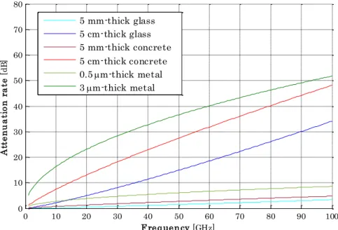
In comparison to the lower frequency bands, the hurdles faced in the mm–Wave range include greater free–space path–loss (PL) due to the increase in frequency as predicted by Friis’ law, greater rain and atmospheric attenuation [23], [24], more foliage losses [25] and more sensitivity to blockage effects [6]. For these reasons among others, the use of mm– Wave in wireless communications has been restricted to specific applications such as short range communications or indoor services. In this regard, the Local Multipoint Distribution Service (LMDS) technology, destined for provision of broadband services to fixed networks, was deployed in the 28 GHz frequency band in the late 1990s [26]. Originally intended for distribution of TV services, this technology has not necessarily reached its envisioned commercial success. The unlicensed 60 GHz band has also attracted considerable interest. The IEEE 802.11.ad standard, also known as WiGig (Wireless Gigabit), was defined in this band [27] in 2012. This technology, intended for Wi–Fi services, enables data rates in the order of Gbps for short range indoor communications.
Current frequency allocations
for cellular systems Millimeter–Wave frequency bands
6 GHz 100 GHz 24.25 – 27.5 GHz 31.8 – 33.4 GHz 37 – 43.5 GHz 45.5 – 52.6 GHz 66 – 76 GHz 81 – 86 GHz
Frequency bands proposed by the ITU at WRC–2015
P. 27 Recently, researchers in the wireless community have been reconsidering the feasibility of mm–Wave for terrestrial mobile communications [28], [29], [30], [6]. Several ways to overcome some of the aforementioned challenges, related with propagation conditions in this frequency range, have been proposed.
Studies in [6] have claimed that the increased free–space PL experienced in higher frequency bands due to the decrease of antenna size can be compensated for. They argue that so long as the antenna effective aperture is kept constant, mm–Wave frequencies will not result in higher free–space PL in comparison to legacy frequencies. This is achievable with the use of directional antennas and/or antenna arrays for more gain.
Authors in [28] and [6] have downplayed the impact of rain and atmospheric attenuation. In [6], it is argued that atmospheric attenuation, essentially noticeable at specific frequencies such as 60 GHz, results in about 15 dB/km attenuation in this frequency band. Such losses are thought to be insignificant in the targeted communications ranges for 5G mm–Wave systems, which are typically less than 200 m. The studies in [28] have also found out that atmospheric absorption and rain attenuation, even at heavy rates, are negligible at frequencies such as 28 and 38 GHz, with only 7 dB/km signal attenuation, which equates to 1.4 dB at 200 m.
It is true that mm–Wave signals are more sensitive to blockage effects than lower frequency signals. In fact, due to the short wavelengths, contributions from diffraction phenomenon for example are relatively insignificant at mm–Wave frequencies in comparison to the lower frequency bands. Therefore, the presence of obstacles may create abrupt changes with signal attenuation up to 40 dB at mm–Wave frequencies according to [6]. The use of adaptive antenna arrays and beam steering solutions can be considered in order to overcome this issue [31].
2.3. Small–cells network densification
Traditionally, macro–cell BSs are mounted on high towers. They are geared to serve a number of terminals within their coverage areas. These macro–cell BSs have been at the center of the evolution of cellular networks. With the looming capacity challenge in the horizon of 5G, further BS deployment is necessary in order to improve the connectivity experience of the end–users. However, this is not a workable solution for macro–cells for
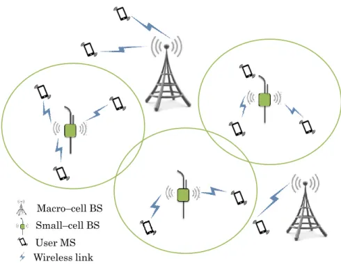
P. 28 numerous reasons including high operational and maintenance costs, lack of available sites and high output power. To circumvent this bottleneck, the concept of network densification by means of small–cells, illustrated in Fig. I.2.3, have gained huge momentum in recent years [32].
Fig. I.2.3 – Illustration of small–cells network densification concept
The idea is to offload parts of the traffic, currently being handled by the macro–cells, through the deployment of a large number of small–cells in a heterogeneous networks (HetNets) configuration. This densification approach is practical for enhancing network capacity in a cost efficient manner as argued in [33]. Furthermore, since small–cells are set to be located much nearer to the terminals compared to conventional macro–cells, better coverage will be achieved [34]. The deployment of small–cells, ranging from micro–cells to femto–cells, will increase the spectrum reuse ratio as the cell sizes become smaller. Thus, it is expected that HetNets will enable significant improvements on key metrics such as spectral efficiency [35].
In addition to these small–cells, HetNets may also include other components such as remote radio heads (RRHs), relays and multi–hop relays which will contribute to further improvements of the network performances.
Macro–cell BS Small–cell BS User MS Wireless link
P. 29 However, with such extremely dense networks, there are several critical challenges that need to be addressed in order to reap the aforementioned benefits.
The sheer number of BSs within HetNets is a source of interferences [32], especially with spectrum reuse being a key aspect for improving spectral efficiency. Solutions to mitigate these inferences include CoMP (Coordinated Multipoint) techniques found in LTE standard as discussed in [36] and enhanced Inter–Cell Interference Coordination (eICIC) [37] adopted in LTE–A standard.
Moreover, mobility is a major concern in HetNets as demonstrated in [38]. The high density of small–cells increases the frequency of handovers for mobile terminals, which was already an issue in macro–cell–based networks. Studies in [39] and [40] have investigated mobility– aware solutions to solve this problem.
Finally, reliable wireless backhauling is mandatory for these HetNets since the high density of small–cells limits the availability of wired backhaul connections. In [41], non–orthogonal multiple access–based solutions have been investigated for this purpose.
2.4. Cloud–based radio access network (C–RAN)
Traditionally, the RAN is made of many standalone BSs. There are, up to now, mainly two network architectures: the single–cell site architecture and the distributed BS architecture, as illustrated in Fig. I.2.4.
Fig. I.2.4 – Traditional network architectures
Base band BBU
RF
RF Single–cell site
architecture Distributed BS architecture
Cable link Fiber link
P. 30 In the single cell site architecture, both the digital unit and the radio unit are housed together within the same structure, linked to the BS antenna by a long cable. However, in the distributed BS architecture, the radio function unit, referred to as RRH, is separated from the digital baseband unit (BBU) by fiber and placed closer to the BS antenna in order to minimize cable losses.
Nevertheless, in both cases, each BS requires its own power supply, conditioning and monitoring system. As massive deployment of additional BSs in the form of small–cells is considered as a promising solution to satisfy the capacity demand of 5G systems, these RAN architectures are not optimal for many reasons including increased susceptibility to interferences and expensive costs.
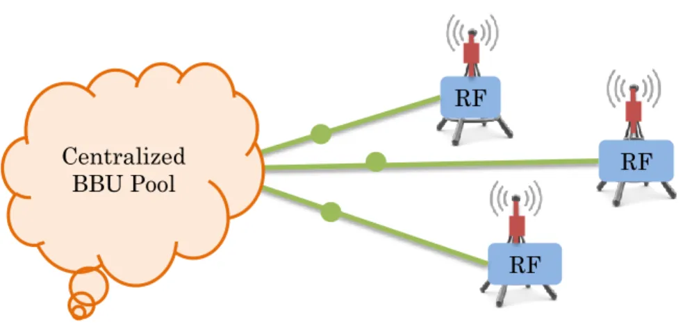
To circumvent these challenges, the concept of cloud–based radio access network (C–RAN) has received considerable attention in the context of 5G [42]. C–RAN is a novel network architecture that can be viewed as an evolution from the distributed BS architecture. As illustrated in Fig. I.2.5, it is based on this same decoupled architecture but on a much larger scale. Multiple BBUs decoupled from the RRHs are pooled into a cloud–like centralized unit, the BBU pool. Therefore, the BBU pool is tasked with baseband signal processing and signal transmission to the RRHs.
Fig. I.2.5 – Cloud–RAN (C–RAN) architecture for 5G RF RF RF Centralized BBU Pool Cable link Fiber link
P. 31 With such network architecture, it is possible to enhance capacity by massively deploying RRHs connected to a centralized cloud with high processing capabilities [43]. C–RAN architecture also enables support of multiple standards, reduced energy consumption and reduced capital expenditure (CAPEX) and operational expenditure (OPEX) for operators [43].
However, one of the main challenges related with C–RAN is the design of the communication layer between the BBU pool and the RRHs, known as the fronthaul network. Generally, optical links are preferred thanks to the available bandwidth but their high cost remains a limitation [43].
2.5. Network function virtualization (NFV)
Future 5G networks are expected to provide multiple services with different requirements. However, hardware–based functions of today’s network are unfavorable for a continuous deployment of additional network services.
To solve this problem, seven of the world’s leading telecom operators, including AT&T, BT, Deutsche Telekom, Orange, Telecom Italia, Telefonica and Verizon, came together through the European Telecommunications Standards Institute (ETSI) to introduce the concept of network functions virtualization (NFV) in 2012.
The idea is to decouple network functions from the dedicated physical infrastructure to a virtual instance. The NFV reference architecture defined by ETSI [44] and illustrated in Fig. I.2.6 can be subdivided in mainly three parts:
The NFV infrastructure (NFVI), which consists of the hardware resources, a virtualization layer and a virtual interface
The Virtual Network Function (VNF), grouping together the virtual functions that can be run on the NFVI hardware resources
The NFV Management and Orchestration (NFV MANO) module, charged with management of the infrastructure through the Virtualized Infrastructure Manager (VIM), management of lifecycle of VNF instances through the VNF manager and control of the network services through the Orchestrator.
P. 32 Fig. I.2.6 – Network function virtualization (NFV) architecture
This virtualization mechanism enables the coexistence of heterogeneous virtual network functions on the same physical infrastructure. It offers great flexibility to service providers in terms of resource management and rapid migration to new technologies. The benefits of NFV also include CAPEX and OPEX reduction and energy saving since the same physical infrastructure can be shared by multiple service providers [45]. However, NFV will face a number of challenges including the design of a simple NFV MANO that accommodates legacy management systems, optimal and flexible VNF instances, robustness against VNFI hardware failures, security and scalability [44], [46].
In addition, NFV will enable network slicing [47], a recurring concept in 5G discussions [48]. First introduced in [45], network slicing consists of creating multiple virtual networks from a single physical infrastructure. These virtual networks are designed to meet specific requirements from users and/or service providers. Network slicing’s target
MANO VNF Virtualization layer NFVI Hardware resources Virtual interface
Virtual function Virtual function Virtual function
Orchestrator
VNF manager
P. 33 implementations include both the core network (CN) and the RAN as illustrated in Fig. I.2.7.
Fig. I.2.7 – Illustration of network slicing concept
2.6. Full–duplex communications
Traditionally, it has been assumed that radio units cannot receive and transmit on the same frequency resource at the same time due to self–interference. Transmission and reception are either alternated via time division, or they occur in different frequency resources. This is referred to as half–duplex (HD) communications.
However, recent research studies have started to invalidate this belief. Studies in [49], [50], and [51] have claimed the feasibility of simultaneous two–way communications, termed as full–duplex (FD) communications, by means of interference cancelation techniques such as antenna cancellation. Device 1 Device 2 Device 3 Device 4 RAN Slice 1 RAN Slice 2 RAN Slice 3 RAN Slice 4 CN Slice 1 CN Slice 2 CN Slice 3 CN Slice 4 NF 1 NF 2 NF 1 NF 2 NF 3 NF 1 NF 3 NF 2 NF 3
P. 34 The self–interference antenna cancellation consists of deploying two transmit antennas, say TX1 and TX2, and one receive antenna, say RX1, on the same radio unit, as shown in Fig. I.2.8. TX1 and TX2 are placed at distances d and
2
d
respectively away from RX1, where denotes the radio signal wavelength.Fig. I.2.8 – Full–duplex (FD) topology for self–interference cancellation
Because of this phase offset of half a wavelength, the signals from TX1 and TX2 cancel out at RX1, thereby significantly reducing self–interference [49]. Further digital and hardware interference cancellation techniques can also be applied to improve FD performances.
The reason FD is considered a key enabling technology for 5G is because it could potentially double spectral efficiency as there is no need for time slot allocation or frequency resource division between uplink and downlink.
However, FD presents some limitations including increased interference effects between users as tackled in [52] and [53], restriction to low power and narrowband communications, and adaptability to real–world scenarios.
2.7. Device–to–device communications
In traditional cellular technologies, devices do not directly communicate with each other without involvement of the network infrastructure. This inherently induces some latency.
d
d
2
TX1 TX
2
RX1
P. 35 Regarding 5G mission–critical applications where ultra–low latency is required, device–to– device (D2D) communications, with very little to no involvement of the network infrastructure, must be enabled.
Besides reduced latency, D2D communications are beneficial for improving throughput and fairness [54]. However, such communications may require that user equipments be able to function as relays. This paradigm shift will face strong challenges ranging from security and privacy to interference management and resource allocation [55], [56]. Additionally, since relaying devices lend their own resources including battery, storage and bandwidth, incentivizing users for their cooperation may be required [55].
3. Focus on millimeter–Wave (mm–Wave) technology
The overview presented in this chapter shows that significant efforts have been put into the development of future 5G communications systems. Innovative technologies are proposed to fulfill the challenging requirements posed by the envisioned 5G applications. With regards to the remaining studies in this Ph.D. project, the focus is on mm–Wave technology.
Although the prospect of mm–Wave technology for mobile communications systems is a very enticing one, there is still a lot of work to be done in order to bring this technology to fruition. Precise knowledge of the mm–Wave propagation channel, yet to be achieved, is paramount to fully assess the feasibility of mobile communications in such frequency bands. Extensive research studies have been conducted worldwide in this regard but some areas still remain insufficiently investigated. Thus, it is our objective in this Ph.D. project, especially in the remaining chapters, to contribute to a better knowledge of the propagation channel properties in these frequency bands than the status quo.
P. 36
Chapter II
II. Millimeter–Wave Channel Modeling
and Characterization for 5G
In this chapter, the literature on mm–Wave channel modeling and characterization for future 5G systems is examined. In Section 1, a review of earlier channel models, developed for frequencies below 6 GHz and intended for 3G and/or 4G systems, is first performed. Then, the shortcomings of these models with regards to 5G requirements are highlighted. In response to the challenges, intensive investigations have been conducted under various European collaborative projects such as METIS, MiWEBA and mmMAGIC. The studies carried out in such projects are discussed in Section 2. The channel modeling studies undertaken in these collaborative projects are mainly fueled by measurement campaigns conducted all over the world by various research groups. These measurement campaigns are critical in channel modeling and characterization as they provide valuable knowledge and the data basis necessary to develop and validate models. Indeed, there are numerous issues related with 5G channel modeling. The support of frequency bands from below 6 GHz up to 100 GHz is an important consideration which many studies have focused on. In this regard, the frequency–dependence of channel large scale parameters (LSPs), which describe the main characteristics of the environment, has been the main interest in these investigations. Therefore, in Section 3, literature results, relevant to this topic, are reported. Finally, our motivations to perform further investigations on this subject are explained in Section 4.
1. Review of earlier channel models
In this section, the most popular channel modeling approaches, adopted in early system simulation and design, are discussed. More specifically, 3GPP, WINNER, COST and IEEE 802.11 efforts on the matter are documented. Following a brief description of these
P. 37 entities, the main characteristics of the proposed channel models are highlighted. Additionally, the shortcomings of these models with regards to 5G requirements are emphasized.
1.1. 3GPP channel models
The 3rd generation partnership project (3GPP) is a cooperation of seven telecommunications standardization bodies, charged with the production of technical specifications meant to be transposed into deliverables by its very organizational partners. These partners include ARIB (Japan), ATIS (North America), CCSA (China), ETSI (Europe), TSDSI (India), TTA (South Korea) and TTC (Japan).
The 3GPP consortium have initially played a big part in the success of geometric channel models (see Chapter III, Section 1 for more details) during the early stages of the work toward 4G networks. Moreover, as MIMO technology began to gain momentum, the need for standardized channel models to evaluate the performances of such a technology was raised. The 3GPP Spatial Channel Model (SCM) [57], introduced earlier in 2003, was then first considered to address this issue. Based on the geometrical principle, the proposed two– dimensional (2–D) model was developed for the 2 GHz frequency band with channel bandwidths up to 5 MHz. The model covers propagation scenarios such as suburban macro– cellular (SMa), urban macro–cellular (UMa) and urban micro–cellular (UMi).
In 2005, its wideband extension referred to as SCM–extended (SCM–E) [58] was developed to support larger bandwidths, up to 100 MHz. This latter model also supports the 5 GHz frequency band as well.
1.2. WINNER channel models
The Wireless World Initiative New Radio (WINNER) was a project initiated under the European FP6 research program, with over forty partners including operators, vendors and academics. Its objective was to develop a unique system concept adaptable to a wide range of communications scenarios.
In WINNER I [59], channel modeling for wideband MIMO was addressed. The proposed model, released in 2005, used very similar approaches as those adopted in the SCM–E [58]. The model was developed, based on measurements performed at 2 and 5 GHz. Multiple
P. 38 propagation scenarios and environments including indoor, UMi, UMa, SMa and rural macro–cell (RMa) are covered in WINNER I and additional features such stationary feeder links are supported.
In WINNER II [60], the studies initiated in WINNER I [59] have continued. The frequency range was extended to the bands between 2 and 6 GHz in WINNER II models, released in 2007. More propagation scenarios and environments, including indoor–to–outdoor (I2O), outdoor–to–indoor (O2I), bad UMi and bad UMa are covered and additional features such as moving networks are supported.
The WINNER family models are geometry–based stochastic channel models (GSCMs). The channel parameters are determined stochastically based on statistical distributions extracted from measurements. Furthermore, in WINNER models, the entire modeling process, i.e. the stochastic definition of the LSPs and the generation of the multi–path components (MPCs), must be specified for each channel instance between the BS and the MS. These models are referred to as “system–level models” [61].
WINNER models have been widely used and, thereby, served as a framework for many studies. For instance, IMT–Advanced channel models [62] released in 2009, are based on WINNER models and also cover the frequency range between 2 and 6 GHz. Later on, WINNER channel models were extended to the three–dimensional (3–D) case in WINNER+ [63] in 2010, with support of the frequency range from 1 to 6 GHz. Similar modeling approaches were also adopted for the 3GPP 3–D channel model [64], released in 2015. This model, however, was developed for the 2 GHz frequency band with channel bandwidth of only 10 MHz.
1.3. COST channel models
The Cooperation in Science and Technology (COST) is a European funded program that brings together researchers from Europe and beyond to ensure a strong position for Europe in scientific and technical research fields. There are about thirty–six member states in COST. The ICT COST Action 2100 addresses the specific topic of mobile and wireless communications. Its objective is to propose solutions enabling the development of next generation communications systems.
P. 39 In COST 2100 [61], a GSCM for MIMO communications was proposed as an extension of earlier models developed in COST 259 and COST 273 [65]. However, unlike WINNER “system–level models”, COST 2100 channel modeling process is based on clusters, i.e. scattering elements, present in the environment and not specific to an individual channel instance. Therefore, once clusters are consistently stochastically defined for a given propagation environment with respect to the BS location, those visible at each channel instance between the BS and the MS are used to synthesize the channel LSPs. These models are referred to as “cluster–level models” [61].
1.4. IEEE 802.11ad channel model
The Institute of Electrical and Electronics Engineers (IEEE) 802.11 committee is a working group, “responsible for writing Wireless Local Area Network (WLAN) standards”. Typically, ranges up to 100 m are targeted and unlicensed spectrum is used.
Therefore, the committee has been interested in channel modeling in the unlicensed 60 GHz frequency band for WLAN standards such as IEEE 802.11ad also known as WiGig. The covered propagation scenarios are indoor environments, typically a conference room. Thus, based on specific measurements and ray–tracing simulations in these specific scenarios, a deterministic cluster–based channel model [66] was proposed in 2010. The modeled paths are the line–of–sight (LoS) path and low order reflections as it was argued that diffracted paths are negligible at 60 GHz. The model is also supportive of antenna arrays and beamforming techniques and takes into account human blockage effects.
1.5. Shortcomings of early channel models with regards to 5G
COST 2100, IEEE 802.11ad and especially WINNER channel modeling approaches found their way into standardized models developed by the 3GPP and/or the ITU. These models have played a key role in the performance evaluation of current cellular systems such as 4G. However, there are some limitations with regards to their use for 5G development.
Both WINNER and COST–based channel models were designed for the evaluation cellular systems, like 3G and 4G, which operated in the frequency bands below 6 GHz. Thus, it is not straightforward to extend their applicability to the frequencies in the mm–Wave bands, targeted for future 5G networks. This is mainly due to the differences regarding the