This is an author-deposited version published in: http://oatao.univ-toulouse.fr/
Eprints ID: 3661
To cite this document: SAQUI-SANNES, Pierre de, APVRILLE, Ludovic. TURTLE:
Four Weddings and a Tutorial. In: Embedded Real Time Software and Systems - ERTSS
2010, Toulouse, 19-21 May 2010
Any correspondence concerning this service should be sent to the repository
administrator:
staff-oatao@inp-toulouse.fr
Page 1/9
TURTLE: Four Weddings and a Tutorial
L. Apvrille
1, P. de Saqui-Sannes
21: Institut Telecom, Telecom ParisTech, CNRS LTCI
2229, routes des Crêtes, B.P. 193, 06904 Sophia-Antipolis, France. ludovic.apvrille@telecom-paritech.fr
2: CNRS ; LAAS ; 7 avenue du colonel Roche, F-31077 Toulouse, France Université de Toulouse ; UPS, INSA, INP, ISAE ; LAAS ; F-31077 Toulouse, France
pdss@isae.fr
Abstract: The paper discusses an educational case study of protocol modelling in TURTLE, a real-time UML profile supported by the open source toolkit TTool. The method associated with TURTLE is step by step illustrated with the connection set up and handover procedures defined for the Future Air navigation Systems. The paper covers the following methodological stages: requirement modeling, use-case driven and scenario based analysis, object-oriented design and rapid prototyping in Java. Emphasis is laid on the formal verification of analysis and design diagrams.
Keywords: Real-Time UML, requirements, analysis, design, deployment, formal verification, code generation.
1. Introduction
A UML profile customizes the Unified Modeling Language [1] for specific needs. A profile definition usually adds formality to the OMG-based notation and stimulates tool development. Like UML, a profile needs to be associated with a method. To convince practitioners that a UML profile, a tool and a method meet their needs, it is important to develop teaching material and to make case studies publicly available. The remark particularly applies to TURTLE [2], the real-time UML profile supported by the open-source toolkit TTool [3]. Therefore, the paper discusses an educational case-study of protocol modeling using TTool, its diagram editors, its formal code generators and interfaces to formal verification tools, as well as its Java code generator. The case study which serves as running example throughout the paper is a subset of the Future Air Navigation System [4]. The connection set up and handover procedures included in the FANS specification document support an explicit description of the TURTLE method, from requirement elicitation to rapid prototyping in Java. The paper particularly points out the benefits of using TTool with formal verification tools [5] [6] [7] and insists on the user-friendliness of the interface TTool offers for linking UML-based modeling and formal verification.
The paper is organized as follows. Section 2 presents the TURTLE language, the toolkit and the method. Section 3 introduces the FANS. Section 4, 5, 6 and 7 respectively address the requirements, analysis, design and deployment stages of the TURTLE method. Section 8 concludes the paper.
2. TURTLE 2.1 Methodology
The TURTLE language reuses and extends SysML and UML diagrams. TURTLE requirement diagrams are based on the SysML syntax [8], whereas use-case, sequence, class, objects and activity diagrams reuse the UML 2 syntax [1].
1. Requirement capture. A SysML-like Requirement Diagram captures informal requirements. Chronograms add formality to temporal requirements. That formality enables formal verification of analysis and design diagrams against temporal requirements [9]. 2. Analysis. A use-case diagram separates the
system from external actors and identifies the functions and services offered by the system. Use-cases are documented by scenarios expressed in terms of sequence diagrams. Scenario instances communicate asynchronously or synchronously and the lifeline of one instance may contain absolute dates, time intervals and timers. An Interaction Overview Diagram (IOD) structures the sequence diagrams in a flow-chart fashion, which enhances modeling capabilities at analysis level. Formal code (e.g. in RT-LOTOS and UPPAAL) may be generated from a set of IODs and sequence diagrams, which enables formal verification of analysis diagrams before design diagrams are created.
3. Design. In terms of architecture, a class/object diagram defines the system as a set of typed objects, and explicitly composes pairs of objects that run in parallel, run in sequence, rendezvous, or preempt each other. Their behaviors are described by activity diagrams that support
synchronization actions and time intervals. Additionally, TURTLE activity diagrams offer non deterministic operators to describe time behaviors and reactivity to environment.
4. Deployment. The software classes identified during the design step are grouped into components. A component diagram is created. Components may be deployed over execution nodes using UML deployment diagrams.
2.2 TTool
The TURTLE toolkit, or TTool for short, belongs to the category of UML front-ends that include code generators for external verification tools, as well as for rapid prototyping. TTool offers user-friendly interfaces to formal verification tools and nicely manages the problem of linking verification results to the identifiers used in the TURTLE model. People with limited knowledge of formal methods may use TTool without reading a line of LOTOS [10], RT-LOTOS [11], or UPPAAL code [12]. The press-button approach implemented for the verification-oriented code generators has been reused for the Java code generator intended for prototyping.
• TTool includes several code generators that enable application of complementary verification techniques, such as model-checking, transition system minimization and observers.
• All diagrams, but the use-case diagram and the
informal part of requirement diagrams, have a formal semantics. Therefore, formal verification applies not only to design diagrams but also to analysis and deployment ones. TTool thus enables to apply formal verification to analysis diagrams where other UML tools apply it to design diagrams exclusively. Knowledge of object-oriented design is therefore not an asset for using TTool. For instance, formal verification may be achieved on scenario-based analysis.
• TTool bridges the gap between the analysis
and design steps. Indeed, it includes a design diagram synthesizer which takes sequence diagrams as input and outputs objects and activity diagrams. Automatically generated design diagrams may be extended manually and formally verified.
3. Case Study: the FANS
The Future Air Navigation System, or FANS for short, is a highly complex system. An excerpt of its specification document was selected for its capacity to convey an intuition of the importance of carefully working on specification documents before starting a TURTLE model, as well as for its capacity to illustrate the TURTLE method in a reasonable time.
The objective of the paper is not to describe the entire FANS system but to exemplify the TURTLE approach on two procedures: the Initial Notification (IN) and the Request For Notification (RFN). IN is a connection set up procedure which authenticates an aircraft to an Air Traffic Control Center (control tower). RFN is as a handover procedure: an aircraft connected to a tower T1 sets up a connection to another tower T2 and releases its connection to T1. The case study is educational. Nevertheless, the starting point of the study is not a text formatted by professors but an industry document in plain English that incompletely and sometimes ambiguously describes the IN and RFN procedures. The original text thus needs to be carefully analyzed in terms of incompleteness, ambiguities and contradictions. The purpose is not only to detect defaults but also to take decisions. The output of that clarification process is a specification document which served as input to elaborate the TURTLE model presented in the rest of the paper. The clarification process is not detailed in the paper in order to leave space for a discussion on the use of TURTLE.
4. Requirements
Discussion in the paper focuses on two requirements attached with the IN and RFN procedures.
• Req1: The IN procedure either completes within
10 minutes or aborts. The pilot accordingly receives a “success” or “abortion” report.
• Req2: The RFN procedure either completes
within 25 seconds or aborts. The pilot accordingly receives a “success” or “abortion” report. Assuming, the aircraft was originally connected to ATC1 and moves to an area controlled by ATC2, then ATC1 receives a message indicating whether RFN completed or not.
The SysML requirement diagram depicted in Figure 1 contains Req1 and Req2, two requirement nodes stereotyped by <<Requirement>>. Each first-level requirement contains three sub-requirements (see the containment relationship). The leftmost sub-requirements deal with success and error messages. The other sub-requirements associate a time constraint related to the first-level requirement.
5. Analysis 5.1 Modeling
The use case diagram contains two main functions (see Figure 2): InitialNotification (IN) and RequestFor Notification (RFN). One may observe that RFN includes IN (see the <<include>> relation). Both IN and RFN use a timer service. For simplicity, the use case diagram contains human actors (FlightCrew and AirTrafficController) and not hardware ones. The diagram further omits maintenance operations. The boot and power off of the system are also ignored.
Figure 2. Use-case diagram
Scenarios expressed by sequence diagrams contribute to better understanding of how the system will work. A scenario describes execution traces that document a function or a service modeled by one or several use cases. Scenarios are usually categorized into two groups that distinguish between nominal behavior and error situations, respectively. In TURTLE, an Interaction Overview Diagram (IOD) allows one to structure the scenarios in a flow chart fashion. In practice, an IOD looks like an activity diagram where actions have been replaced with references to sequence diagram names.
The IN procedure is not complex, which explains why all the traces may be modeled by an easy-to-read IOD and simple sequence diagrams. The RFN procedure is far more complex and the entire IOD would have around 50 nodes. Consequently, the model of the RFN discussed hereby assumes no message but Contact_Advisory may be lost.
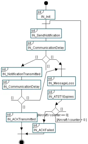
The IOD associated with the IN function is depicted in Figure 3. It includes the following scenarios:
1. IN_Init: the fight crew sends a “startInitialNotification” message to the aircraft, and the latter sets its retransmission counter to 3.
2. IN_SendNotification: the aircraft sends a “Notification Contact” to the communication medium, and sets the ATST1 timer.
3. IN_CommunicationDelay: a communication non-deterministic delay is applied to the messages transiting through the communication medium.
4. IN_NotificationTransmitted: the communic-ation medium forwards a notification message to an Air Traffic Controller (ATC), i.e. to a tower. The scenario uses a non-deterministic delay to model the computation time the ATC takes to issue the notification, and follows up sending an acknowledgement (AFN_ACK) to the communication medium. Figure 1. Requirement Diagram
Figure 3. Interaction Overview Diagram 5. IN_MessageLoss describes an error
situation: the communication medium has lost a message.
6. IN_ATST1Expires: the aircraft did not receive any acknowledgment on time; the ATST1 timer expires and the retransmission counter is decreased by 1.
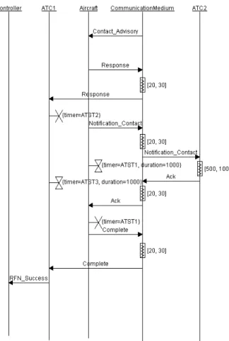
7. IN_ACKTransmitted: the acknowledgement is forwarded from the communication medium to the Aircraft. The Aircraft resets its timer, and sends an IN_Success message to the crew (see Figure 4)
8. IN_Failed: the aircraft notifies the crew with a failure message.
Figure 4. Initial Notification, IN_ACKTransmitted scenario
The seven scenarios associated with IN are structured by an IOD. Scenarios 1, 2, 3 are executed in sequence. Then, a notification may be correctly transmitted (scenario 4) or lost (scenario 5). When the notification is correctly transmitted, a response is sent to the Aircraft (scenario 3). The IN procedure completes if the response is correctly transmitted (scenario 7). Otherwise the response is lost (scenario 5); the ATST1 timer expires (scenario 6) and the counter of the Aircraft is decreased by 1. If the counter equals 0, the IN procedure fails (scenario 8). Otherwise, the Aircraft retransmits a notification to the ATC.
The IOD associated with the RFN procedure is far more complex. The number of messages increases and so does the number of potential messages losses. Given the difficulty to model all possible traces using scenarios, the IOD associated with RFN considers that no message may be lost, but the ContactAdvisory message sent from ATC1 to the Aircraft (Figure 5).
RFN is modeled as the interconnection of five scenarios:
1. RFN_Init: initialization of a counter in ATC1 (no more than three retransmissions in case of message loss).
2. RFN_ContactAdvisory: ATC1 transmits the Contact_Advisory message to the Aircraft. 3. RFN_LossOfContactAdvisory: the message
named Contact_Advisory is lost during its transfer through the communication medium. 4. RFN_Failed: the failure of the overall RFN
procedure is notified to the controller.
5. RFN_NoLoss: the RFN procedure is successful (see Figure 6).
Figure 5. Request For Notification – Excerpt of the Interaction Overview Diagram
Figure 6. Request For Notification – RFN_NoLoss scenario
5.2 Verification
An IOD and all the sequence diagrams it references serve as starting point to generate a formal specification in RT-LOTOS, LOTOS or UPPAAL. The RTL verification tool developed for RT-LOTOS generates a reachability graph (rg1) with 51 states and 82 transitions for the IN procedure. The graph rg2 generated for the RFN procedure has 359 states and 539 transitions. Formal analysis of the two graphs draws the following conclusions:
• Req1: the only deadlock states of rg1 are the states whose leading transition is either IN_Success or IN_Failed. This may be verified by minimizing rg1 with respect to startInitialNotification, IN_Success and IN_Failed (Figure 7).
• The IPN_AbortionReport requirement can be proved the same way.
• The IPN_TimeConstraint requirement is proved in a different way. A graph with timing information (a “DTA” [11]) is generated. Timing information enables to deduce at what time the actions contained in the sequence diagrams may be performed. Another way to do this is to use an observer, a technique
exemplified later on in the paper (for design diagrams).
Using graph generation and minimization techniques, Req2 has been also proved to be satisfied by the RFN procedure.
Figure 7. Quotient automaton – Formal verification of analysis diagrams, IN procedure
6. Design 6.1 Design generation
A first version of the architecture and behaviours of the system have been obtained using TTool’s automatic design synthesizer. The latter took as input the IOD and the sequence diagrams referenced by that IOD (see section 5). The object diagram and activity diagrams output by the design synthesizer do not represent the entire system. The architecture is built upon analysis instances, and thus results from an automated procedure, not from an experience the designer may have in object-oriented design. The main advantage of using the design synthesizer is to propose a seamless transition from analysis to design and to limit copy/paste errors.
The synthesized design needs to be enhanced with architecture information. Examples include functions organized into classes, messages parameterized with more complex data structures, and explicit modeling of routing inside the communication medium making the notion of sending and receiving entity appear. Our analysis model contains two IODs: one for IN, one for RFN. Given the design synthesizer accepts one IOD as input, we have to compare the pros and cons of two options:
• Generating a design from the IOD of IN.
The advantage is that the analysis diagrams of IN model all possible traces, including message losses. The design generated from IN nevertheless needs to be enhanced with the RFN functions.
• Generating a design from the IOD of RFN.
The advantage is that the analysis diagrams of RFN also contain a model of IN, since IN is a subpart of RFN. Unfortunately, the analysis models of RFN do not model all message losses.
Let us consider the design generated
option. It contains five classes that one by one correspond to an entity identified during the analysis stage. The entities are: Timer__ATST1
CommunicationMedium, FlightCrew and These classes rendezvous on synchronization gates The gates’ names match the names of the
exchanged by the entities in sequence diagrams 6.2 Reworking the design
The architecture and behavioral diagrams synthesized by TTool serve as reference for a manually improved class diagram:
• A Timer class taken from the generated design is instantiated twice by two TObjects ATST1:Timer and ATST2_ATST3:Timer
• A class named AircraftEmbeddedSystem models the embedded system of the Aircraft entity identified at analysis step. The name change helps identifying the targeted system
• A class CommunicationMedium
communication medium which links the two control towers and the aircraft. The message no longer transmits untyped messages, but TData which is a class modeling a data structure with several fields: a message source address, a destination address and a data field. Examples of IDs include Contact_Advisory and Response.
• A class ATCEmbeddedSystem is twice (ATC1, ATC2) to model handover between two towers.
• An Environment class models all interactions between the system and its environment. Environment gathers the behavior of the flight crew and the controllers. The architecture is verification-centric.
The design generator not only constructs the architecture of the system but also provides behavior to the classes. The activity diagrams associated with the classes are revisited. example, the messages identified by their names in sequences diagrams are now modeled as Protocol Data Units. Also, the Air Tower Control is a generic class that models the three roles described in the FANS: the role played in the IN procedure, and the two roles that an ATC can play in the RFN: an the origin of a handover or an ATC at the destination of the handover.
6.3 Formal verification
Formal verification combines the observer technique with graph minimization and model
techniques. Req1_Observer verifies Notification procedure completes within 10 Req1_Observer generates an IN_DONE case of successful termination and an
generated for the first that one by one identified during the analysis Timer__ATST1, Aircraft, and ATC1. synchronization gates. The gates’ names match the names of the messages
es in sequence diagrams.
The architecture and behavioral diagrams serve as reference for a taken from the generated two TObjects: ATST2_ATST3:Timer.
AircraftEmbeddedSystem models the embedded system of the Aircraft . The name ng the targeted system. models the ich links the two The message no longer transmits untyped messages, but a a class modeling a data message ID, a address, a destination address and a Examples of IDs include
.
is instantiated to model the RFN class models all the interactions between the system and its gathers the behavior of the flight crew and the controllers.
centric. The design generator not only constructs the
ystem but also provides a full . The activity diagrams associated with the classes are revisited. For identified by their names in modeled as Protocol ontrol is a generic three roles described in the the role played in the IN procedure, and the ATC can play in the RFN: an ATC at ATC at the destination
observer technique with graph minimization and model-checking r verifies the Initial procedure completes within 10 seconds.
IN_DONE action in error action
otherwise. Req2_Observer verifies procedure completes within
Req2_Observer generates RFN_DONE or depending on the completion result
diagram of Req2_Observer is given
Figure 8. Activity Diagram – Excerpt with a mark for reachability accessibility
Req1 and Req2 were verified using two complementary tools: RTL and UPPAAL.
The screenshot in Figure 9 verification of Req1 and Req2 reachability graph generated by RTL
and 20000 transitions. Without reading a line of RT LOTOS code or scanning the file containing the graph, the user of TTool uses
provided by TTool’s interface to prove that none the graph’s transition is labeled by
Figure 9. Reachability graph Formal verification draws to the conclusion
and the RFN procedures respectively completes within 10 and 25 seconds after being triggered by the
verifies the RFN completes within 25 seconds. generates RFN_DONE or error depending on the completion result. The activity diagram of Req2_Observer is given in Figure 8.
Excerpt with a mark for reachability accessibility
were verified using two RTL and UPPAAL.
igure 9 refers to formal verification of Req1 and Req2 using RTL. The generated by RTL has 7000 states Without reading a line of RT-LOTOS code or scanning the file containing the
s the search facility provided by TTool’s interface to prove that none of
by “error”.
Reachability graph - Statistics Formal verification draws to the conclusion that the IN
respectively completes after being triggered by the
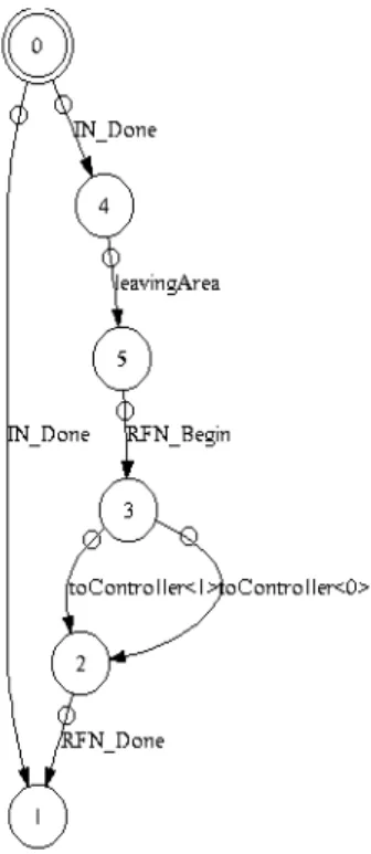
pilot. This does not suffice to prove that the system is not in an infinite 0-time loop (a situation where actions can be performed infinitely whilst time does not evolve). To prove the two procedures, once started, always reach a termination state, the reachability graph may be minimized with respect to the actions of the Environment. Figure 10 depicts the quotient automaton generated by a minimization algorithm, using the relation defined in [13]. The system always performs an “IN_DONE” (i.e. there is no infinite loop in IN). Also, each time an RFN_Begin action is performed, the system eventually performs an RFN_DONE action (i.e., there is not infinite loop in RFN). We thus come to the conclusion that Req1 and Req2 are proved.
Figure 10. Quotient automaton – Formal verification of design diagrams
Req1 and Req2 may also be proved using UPPAAL. TTool makes it possible to directly enter model-checking formulas that are transparently checked by UPPAAL in the sense that only the result is displayed to the user of TTool. Also, one right click on an action of an activity diagram (In Figure 8, see the red cross on the “error” action) suffices to directly check for the accessibility and liveness of that action. Again UPPAAL is transparently used.
Proof of Req1 and Req2 with UPPAAL includes the following intermediate proofs:
• The IN_Done action is always accessible (liveness).
• The RFN_Begin action is reachable.
• None of error actions is reachable, which means that both procedures are completed within their required deadlines (10 seconds for IN, 25 seconds for RFN) temporal specification.
• The following formula – translated in CTL - is satisfied: “either the IN fails or succeeds. If it succeeds, the RFN is started and always completes” (see on Figure 11, “Custom formulae”).
Figure 11. Formal Verification of Req1 and Req2 using the TTool interface for UPPAAL
7. Deployment
The deployment phase consists in mapping “software components” on execution nodes, and generating prototyping code to test the system in more realistic conditions. In TURTLE, software components are usually built upon classes extracted from the design. The deployment diagram developed for the FANS system includes four nodes (Figure 12):
• The embedded system of the aircraft,
• The first Air Tower Control,
• The second Air Tower Control, and
• The communication system, in fact its routing application.
For prototyping purposes, the four execution nodes receive a network name which is the one of the
computer on which the code is expected to be tested. For example, the “Aircraft” node is expected to run on a computer node called “neac”.
The nodes are interconnected using UML links. The latter are enhanced with parameters: expected delay of the link, protocol used to send data on that link, and connections between synchronization gates. For example, when a class from the package “PkgAircraft” sends a data on the gate “wi_out”, that data is sent to the package PkgRouter using the UDP protocol to the destination port 6542 located on “orgnac”.
The deployed packages have been built as follows, reusing classes defined at design stage:
• PkgATC1 and PkgATC2 contain the ATCEmbeddedSystem class, and a Timer class.
• PkgAircraft contains the
AircraftEmbeddedSystem class, and a Timer class.
• PkgRouter contains the
CommunicationMedium class.
To test that deployment, the Java code generator of TTool was activated using a press button approach. Once the code has been generated, it can be compiled using, e.g., the javac compiler provided by SUN. At last, the code can be executed on the computer mentioned in the deployment diagram.
Figure 13 shows what happened when the first ATC, the Routing application, and the Aircraft were started. At first, the routing application, and then the ATC1 are started. Then, the aircraft is started: it sends a Notification_Contact message to the Routing application, which forwards than message (UDP packet) to ATC1. ATC1 sends the response (Notification_Ack), and ask the Aircraft to contact ATC2 (Contact_Advisory). And so on.
8. Conclusions
The paper discusses an educational case study of protocol modeling using TURTLE, a real-time UML profile supported by the open-source toolkit TTool. The FANS system was selected to illustrate the TURTLE method and to highlight the set of features that makes TTool different from other UML tools. Examples include automatic synthesis of design diagrams from analysis ones, user-friendly access to complementary verification tools, formal verification of analysis diagrams prior to design diagrams definition, and automatic generation code from verified component and deployment diagrams.
The TURTLE toolkit has evolved over the past six years. First wedding was between UML and the RT-LOTOS process algebra. Second wedding interfaced the TURTLE toolkit with formal verification tools. Figure 12. Deployment diagram
Third wedding linked TURTLE and rapid prototyping in Java. The last wedding was between SysML requirements and TURTLE. The story goes on with the tutorial presented in the paper.
9. References
[1] UML, The Unified Modeling Language, http://www.omg.org/spec/UML/2.2/Infrastruct ure/PDF/.
[2] L. Apvrille, C. Lohr, J.-P. Courtiat,
Saqui-Sannes: TURTLE: A Real-Time UML Profile Supported by a Formal Validation Toolkit, IEEE Trans. on Software Engineering, vol. 30, no. 7, July 2004. [3] LabSoc: TTool: The TURTLE Toolkit,
http://labsoc.comelec.enst.fr/turtle/ttool.html [4] FANS (Future Air Navigation System),
http://en.wikipedia.org/wiki/Future_Air_Navig ation_System.
[5] CADP: http://www.inrialpes.fr/vasy/cadp [6] RTL (Real-Time Lotos Laboratory)
http://www.laas.fr/RT-LOTOS/index.html.en [7] UPPAAL:http://www.uppaal.com/
[8] SysML,
http://www.omg.org/spec/SysML/1.2/Beta2/PDF/
[9] B. Fontan, Méthodologie de conception de systèmes temps réel et distribués en contexte UML/SysML, Doctorat de l’Université de Toulouse, Janvier 2008. [10] Open Systems Interconnection, A Formal
Description Technique Based on the Temporal Ordering of Observational Behaviour, Standard 8807, July 1987
[11] J.-P. Courtiat and C.A.S. Santos and C. Lohr and B. Outtaj, Experience with RT
Temporal Extension of the LOTOS Formal Description Technique, Computer
Communications, vol. 23, n. 12, pages 1104 1123, 2000.
[12] Gerd Behrmann and Alexandre David and Kim G. Larsen, A tutorial on UPPAAL, Technical Report, Department of Computer Science, Aalborg University, Nov. 2004. Third wedding linked TURTLE and rapid prototyping in Java. The last wedding was between SysML requirements and TURTLE. The story goes on with
, The Unified Modeling Language, http://www.omg.org/spec/UML/2.2/Infrastruct
urtiat, P. de Time UML upported by a Formal Validation
, vol. 30, no. 7, July 2004. The TURTLE Toolkit, http://labsoc.comelec.enst.fr/turtle/ttool.html FANS (Future Air Navigation System), http://en.wikipedia.org/wiki/Future_Air_Navig
http://www.inrialpes.fr/vasy/cadp. Time Lotos Laboratory):
LOTOS/index.html.en. http://www.uppaal.com/.
http://www.omg.org/spec/SysML/1.2/Beta2/PDF/. dologie de conception de systèmes temps réel et distribués en
Doctorat de l’Université de Toulouse, Janvier 2008. Open Systems Interconnection, A Formal Description Technique Based on the Temporal Ordering of Observational r, Standard 8807, July 1987 P. Courtiat and C.A.S. Santos and C. Lohr and B. Outtaj, Experience with RT-LOTOS, a Temporal Extension of the LOTOS Formal
Computer
Communications, vol. 23, n. 12, pages 1104-Behrmann and Alexandre David and Kim G. Larsen, A tutorial on UPPAAL, Technical Report, Department of Computer Science, Aalborg University, Nov. 2004.
[13] J. F. Groote and F. Vaandrager (1990). An efficient algorithm for branching bisimulatio and stuttering equivalence.
the 17th ICALP (Warwick), LNCS 443, pp. 626-638, 1990
Figure 13. Execution trace
J. F. Groote and F. Vaandrager (1990). An efficient algorithm for branching bisimulation
ering equivalence. Proceedings of the 17th ICALP (Warwick), LNCS 443, pp.