HAL Id: hal-01008878
https://hal.archives-ouvertes.fr/hal-01008878
Submitted on 8 Jul 2018HAL is a multi-disciplinary open access
archive for the deposit and dissemination of sci-entific research documents, whether they are pub-lished or not. The documents may come from teaching and research institutions in France or
L’archive ouverte pluridisciplinaire HAL, est destinée au dépôt et à la diffusion de documents scientifiques de niveau recherche, publiés ou non, émanant des établissements d’enseignement et de recherche français ou étrangers, des laboratoires
To cite this version:
Sébastien Granger, Ahmed Loukili, Gilles Pijaudier-Cabot, Mouloud Behloul. Self healing of cracks in concrete: from a model material to usual concretes. Second International RILEM Symposium on Advances in Concrete through Science and Engineering, Sep 2006, Québec, Canada. �hal-01008878�
SELF HEALING OF CRACKS IN CONCRETE: FROM A MODEL
MATERIAL TO USUAL CONCRETES
Sébastien Granger (1), Ahmed Loukili (1), Gilles Pijaudier-Cabot (1) and Mouloud Behloul (2) (1) ERT R&DO, GeM – Ecole Centrale de Nantes, France
(2) Lafarge – Paris, France
Abstract
This paper deals with the self healing of cracks phenomenon, in concrete, and especially with its role on mechanical properties. In a first phase, an experimental program, including mechanical tests, acoustic emission investigation and SEM observations, is carried out on an ultra high performance concrete, considered as a model material. This concrete is characterized by its low Water/Cement ratio, which implies that the quantity of potential reactive compounds in the microstructure upon cracking is very high. Prismatic notched specimens are damaged under three points bending and then totally immerged in water for different ageing times, so as to activate the self healing phenomenon, only possible in presence of water. After this ageing phase, the mechanical behaviour of the healed specimens is characterized by means of three points bending tests. A fast recovery of global stiffness and a slight improvement of structural strength are thus highlighted, depending on the time of ageing. Acoustic emission is also performed on this model material. In order to follow the micro-cracking processes and to show that the mechanical contribution of the self healing is related to the precipitation of crystals in the pre-existing crack, the specimens are instrumented with an acoustic emission system, during all the tests. 2D location maps of micro-cracks are thus obtained and clearly show the micro-cracking of the newly formed crystals for healed specimens. The analysis of the cumulative number of detected events, and of the energy extracted from each detected signals highlight the two damage regimes for healed specimens, the newly formed crystals damage followed by the continuation of the pre-existing crack propagation. This research work on the model concrete is completed with microscopic investigations by SEM, which show that new C-S-H have precipitated in the cracks. The same mechanical tests are then applied to usual concretes, and the influence of mix design on the phenomenon is analysed. Four different concretes, with Water/Cement ratio from 0.3 to 0.5, and including silica fume or not, are analysed, and the mechanical behaviour of healed specimens from these concretes is characterized.
1. INTRODUCTION
For many concrete structures in the course of their lifetime or close to their end, the assessment of durability is a key parameter needed in order to know whether safety and security is still ensured or not. The presence of cracks, due to mechanical stresses or time dependent effects (creep, shrinkage…) is one of the major factors which can influence on durability and serviceability, in terms of resistance, permeability or transfer properties.
Self healing of cracks is a phenomenon acting positively on these durability problems. The phenomenon is only possible in presence of water (dissolved CO2 in water is not always
needed) and consists in chemical reactions of compounds present on the crack surfaces. These reactions produce new crystals, and the accretion of these from the opposite surfaces of the crack bridges it eventually, so that continuity can be re-established. The essential requirement, with water, is the presence of compounds capable of further reaction. Thus, cement and cementious materials, hydrated or unhydrated, are the other essential element of the phenomenon. There are two major hypotheses regarding the reactions of healing [1]: the hydration of anhydrous clinker available in the microstructure of hardened concrete, and the precipitation of calcium carbonate CaCO3. The first hypothesis requires water only, when the
second one requires the presence of carbon dioxide in addition. Silting up of cracks or deposition of debris can also contribute to healing, in a minor part.
The majority of research works carried out on this topic highlights the phenomenon by means of water permeability tests. A diminution of flow rate through cracked specimens is the main method to show the self healing of cracks. Edvardsen [2] performed such tests, conducted on small concrete specimens, with a single tension crack each. The typical results show a significantly decreasing rate at the early stages, and then leakage quickly drops to a reduce level. These results highlight the two regimes of the reaction, first immediate reaction on the surfaces of cracks, and then reaction by diffusion through the newly formed crystals. Edvardsen explains the phenomenon by the crystallisation of calcium carbonate exclusively. Hearn [3, 4] carried out also water permeability tests on mortar, with 25% anhydrous clinker, and water cured concrete, containing an insignificant amount of unhydrated clinker. The author investigates the chemical effects, like continuing hydration, dissolution and deposition of soluble species. Chemical analysis of water, inflow and outflow, points out a significant increase in Ca2+ concentration in outflow, which indicates a phenomenon of dissolution-precipitation, especially of calcium carbonate. Such experiments have also been performed by Reinhardt et al. [5], who investigate the role of temperature and of crack width. In brief, these main investigations show that the phenomenon is of particular importance for problems of transfer and watertightness, because it diminishes leakage through cracks.
Concerning the mechanical impact, a few studies have been conducted. Jacobsen et al. [6] performed tests on concrete cubes damaged by freeze/thaw cycles, and then stored in water. Damage and self healing were measured by frequency resonance and compressive strength. Freeze/thaw cycles led to loss in both resonance frequency and compressive strength, and self healing gives a substantial recovery of the frequency, but only a small recovery of compressive strength, which was explained by the fact that cracks were only partly filled with new products. SEM observations conducted show that the most of the crystals seen in the cracks are new C-S-H. Pimienta et al. [7] also provide some insights about the mechanical properties of healed specimens. The authors also reported that the frequency resonance of specimens damaged and then aged in water, tends to recover its initial value. Nevertheless,
knowledge about the mechanical properties is scanty, and this contribution aims at providing some new insights concerning the mechanical behaviour of healed concrete.
An experimental program is developed, first, on an ultra high performance concrete, considered as a model material. Prismatic notched specimens are damaged under three points bending and then totally immerged in water for different ageing times. After this ageing phase, the mechanical behaviour of the healed specimens is characterized by means of three points bending tests, and compared with the mechanical behaviour of non-healed cracked specimens. Acoustic emission analysis and SEM observations are also performed in order to show that new crystals have crystallized in the cracks and to qualify these crystals. Then, the same mechanical tests are conducted on four usual concretes, with different Water/Cement ratio, in order to analyse the influence of concrete composition on the phenomenon.
2. THE EXPERIMENTAL PROGRAM
2.1 Concrete specimens
The first part of the experimental program is carried out on an ultra high performance concrete (UHPC), with a low Water/Cement ratio close to 0.2. This implies that the amount of anhydrous clinker in the microstructure is very high, in the order of 50% [8]. This concrete is considered as a model material for this research work, because of this specificity. In fact, the quantity of potential reactive compounds upon cracking is very high. The composition of this concrete consists of sand, water, cement, silica fume and a superplasticizer. In order to have a localized crack during the mechanical tests, a notch of depth 20 mm and thickness 1.5 mm is performed in each specimen by placing a plate at the midpoint perpendicular to the long direction of the mould. After casting, the concrete specimens (with dimensions of 50x100x500 mm3) are cured for 2 days at 20°C and 100% relative humidity. A thermal treatment is then applied, so as to accelerate hydration and activate the pouzzolanic reaction. The specimens are placed in a climate chamber with a controlled environment of 90°C and 100% relative humidity during 48 hours. With this treatment, concrete is stable, and exhibits very low creep and shrinkage [9, 10].
2.2 Mechanical test configuration
The principle of the mechanical tests carried out is a preliminary phase aimed at cracking the prismatic notched specimens, followed by the ageing in specific conditions, enabling self healing or not, and then the mechanical characterization of these aged specimens.
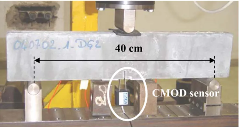
During the first phase of the mechanical program, specimens are loaded under three points bending (figure 1). The tests are notch opening controlled with a constant rate of 0.05 µm/s. The aim of this first step is to get a controlled cracking of the specimen. Pre-cracking is performed in the post peak regime: after having reached the peak (comprised between 3 and 4 kN), unloading is performed when the applied load reaches 2 kN, which represents approximately 60% of the peak load. Thus, a single residual crack width of 10 µm, which permits to get a fast self healing, is aimed. This unloading is also notch opening controlled with the same rate as loading. Pre-cracking phases are quite reproducible and residual crack widths for specimens after unloading range between 8 µm and 15 µm.
Figure 1: Mechanical test configuration
After this first step, the specimens are stored in specific conditions for ageing. Five different periods of ageing have been selected: 1, 3, 6, 10 and 20 weeks. There are two kinds of ageing: for each period, cracked specimens have been stored in water, and others in air. Specimens aged in water have been totally immerged in tap water at 20°C, with nor movement neither renewal. Specimens aged in air have been stored at 20°C and 50% relative humidity. After each period of ageing, the last step of the experimental program consists in reloading the specimens under three points bending, in order to characterize their residual mechanical behaviour. Tests are also notch opening controlled and are conducted until total failure.
2.3 Acoustic emission acquisition
In order to follow and to characterize the cracking processes, all the specimens are instrumented with an Acoustic Emission (AE) system, during the pre-cracking and reloading phases. The aim is to locate the microcracks (called AE events) which appear during the tests. The instrumentation consists of a MISTRAS system, a general-purpose interface bus (for extraction of AE parameters, such as amplitude, energy, duration…) and a PC for data storage analysis. Four piezoelectric transducers (with a resonance frequency of 150 kHz) are placed in a rectangular array just above the notch of the specimens, in order to cover the expected zone of crack path, and to minimize errors in the AE event location algorithms. The dimensions of the rectangular array are 140x65 mm2 (figure 2). The transducers are placed on one side of the specimen, and coupled to the material with a silicon glue. The detection value (in amplitude) is set to 35 dB, in order to overcome the background noise, and the detected signals are amplified with 40 dB gain amplifiers. The frequency range of acquisition is set from 20 kHz to 400 kHz.
A planar location algorithm is used for AE location. It is based on the triangulation of the differences between detection times by each transducer. Three transducers are enough, but the accuracy is improved with an additional one. For the UHPC used in this research work, the accuracy of location, checked with Hsu Nielsen simulations, is ±3 mm, which is correct in comparison with the diameter of the transducers (15 mm). We do not take into account the thickness of the beam, and all the events detected within the thickness of the specimen are projected onto the same place in the 2D maps.
CMOD sensor
Figure 2: Acoustic emission instrumentation – Rectangular array of 140x65 mm2
3. MECHANICAL CHARACTERIZATION OF THE SELF HEALING
OF CRACKS
Three kinds of mechanical results are presented on figure 3. These are curves for a specimen pre-cracked and then reloaded immediately, and for specimens cracked and aged during three weeks (before reloading) in water and in air. The objective of this figure is to show the effect of storage in water, and to compare with the storage in air and with the immediate reloading of the specimen. The curves display the applied load versus the crack mouth opening displacement (CMOD). Each curve presents two parts: the pre-cracking phase, consisting in loading and unloading when the applied load reaches 2 kN in the post peak regime, and the reloading phase, immediate or after ageing.
0 1 2 3 4 5 0 10 20 30 40 50 60 70 80
cracking and immediate reloading cracking and 3 weeks ageing in water cracking and 3 weeks ageing in air
Load (kN)
Crack mouth opening displacement (µm)
Figure 3: : Mechanical behaviour of a specimen cracked and immediately reloaded, of a
specimen cracked and aged 3 weeks in water before reloading, and of a specimen cracked and aged 3 weeks in air before reloading – Pre-cracking and reloading phases
sensor PCI -card
sensors
The reproducibility of the pre-cracking phase of the tests can be seen on this figure. It also shows that the cracked specimen immediately reloaded and the specimen aged in air, have the same mechanical behaviour while reloading, which is the typical reloading after cracking. On the contrary, there is a difference with the mechanical behaviour for the specimen stored in water, especially on the reloading stiffness and the reloading peak load.
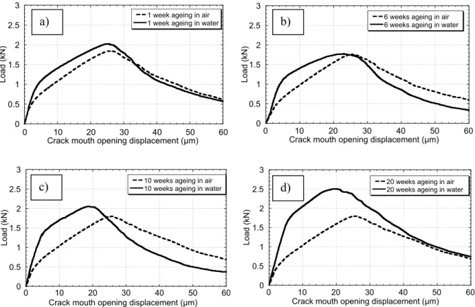
If we consider the influence of the ageing time, which is, of course, an important parameter, figure 4 presents the average reloading curves for specimens stored in air and in water (reloading curves for 3 specimens), and for 4 different periods of ageing: 1, 6, 10 and 20 weeks. For the sake of clarity, only the reloading parts of the total curves are presented. The CMOD at the beginning of the tests is shifted to 0, in order to have the same initial state, but in reality we should have the value of the residual CMOD at the end of the pre-cracking phase. 0 0.5 1 1.5 2 2.5 3 0 10 20 30 40 50 60
1 week ageing in air 1 week ageing in water
Load (
kN)
Crack mouth opening displacement (µm)
0 0.5 1 1.5 2 2.5 3 0 10 20 30 40 50 60
10 weeks ageing in air 10 weeks ageing in water
Load (
kN
)
Crack mouth opening displacement (µm)
Figure 4: Mechanical reloading behaviour of aged specimens for different ageing times – Comparison ageing in water and ageing in air - Average curves: (a) 1 week, (b) 6 weeks, (c)
10 weeks, and (d) 20 weeks
We can notice that specimens stored in air exhibit very similar mechanical behaviour for the different periods of ageing. It means that air has no influence on the mechanical properties of cracked specimens, even for a long period of ageing. The reloading part corresponds to the re-opening of the existing crack until the reloading peak load, followed by the continuation of the crack propagation. On the contrary, there is a clear evolution of the mechanical behaviour
0 0.5 1 1.5 2 2.5 3 0 10 20 30 40 50 60
20 weeks ageing in air 20 weeks ageing in water
Load (kN)
Crack mouth opening displacement (µm)
0 0.5 1 1.5 2 2.5 3 0 10 20 30 40 50 60
6 weeks ageing in air 6 weeks ageing in water
Load (kN)
Crack mouth opening displacement (µm)
a) b)
of specimens stored in water with the time of ageing. The initial reloading stiffness is not the same as for specimens aged in air, and it increases. There is also a slight improvement of flexural strength and a change in stiffness in the pre-peak phase which evolves with time.
In order to get a confirmation that these observed mechanical behaviours are due to the self healing of the pre-existing crack and not to the evolution of concrete itself in water, the average result of tests conducted on specimens which have been stored in water for 10 weeks, and then cracked and immediately reloaded, is compared with the mechanical behaviour of specimens pre-cracked and aged 10 weeks in water. It shows that storage in water without crack does not improve the mechanical properties of the specimen. We have the same mechanical behaviour as those of a non-aged specimen cracked and immediately reloaded: there is no curing effect by storing in water, and it is a consequence of the thermal treatment. So, the evolution of the mechanical behaviour established for cracked specimens stored in water can indeed be explained by the self healing of cracks phenomenon, and not by the bulk improvement upon ageing.
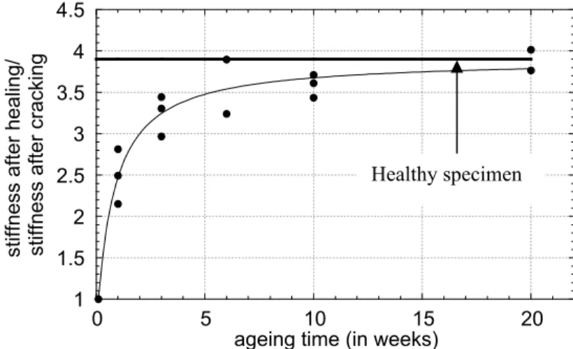
Figure 5 shows the evolution of the ratio between the reloading stiffness with healing, and the reloading stiffness without healing, as a function of the ageing time. It is noticeable that there is a fast recovery by self healing, and this stiffness tends to those of healthy specimen, which is represented by the straight line on the graph. These results can be explained by the fact that products are formed in the crack, especially, if we consider the low W/C ratio, new C-S-H. These crystals make a bridge between the two faces of the crack and progressively fill it, making the specimen recover its initial stiffness.
Concerning the flexural resistance, figure 6 represents the evolution (with the ageing time) of the peak load upon reloading for healed specimens. It shows that self healing provides a slight improvement of strength, compared with the strength of non healed specimens. Nevertheless, the initial flexural strength is not reached, and a kind of explanation wil be provided according to SEM observations, later in the contribution.
1 1.5 2 2.5 3 3.5 4 4.5 0 5 10 15 20
stiffness after healing/ stiffness after cracking
ageing time (in weeks)
Figure 5: Evolution of the ratio between the reloading stiffness with healing and the reloading stiffness without healing, as a function of time of ageing – Comparison with the average
stiffness of healthy specimens
1.8 2 2.2 2.4 2.6 0 5 10 15 20 Rel oadi ng peak l oad (kN)
ageing time (in weeks)
Figure 6: Evolution of the reloading peak for healed specimens (storage in water) with the time of ageing – Comparison with the average reloading peak of non healed specimen
4. THE PRECIPITATION OF NEW CRYSTALS
4.1 Acoustic emission analysis
The mechanical tests have shown the contribution of the self healing phenomenon on the mechanical properties of initially cracked specimens. The main aim of the acoustic tests performed during the mechanical tests is thus to highlight that this contribution is related to the precipitation of new crystals in the crack. The principle is to analyse micro-cracking during the reloading phase of the mechanical tests. So, location maps of micro-cracks are performed during the two steps of the mechanical tests, pre-cracking and reloading after ageing. The first kind of maps illustrates the initial micro-cracking processes and serves as a reference for the second one. The typical maps exhibit a very dense area of micro-cracks in the zone of crack path. In order to have an accurate location of the acoustic events in the macro-crack, we need to filter the detected signals. Otsuka [11] have shown that 95% of the dissipated acoustic energy is located in the fracture process zone, and that the less energetic micro-cracks are not associated with the fracture process of concrete. After having selected the events with the most important energy, we have decided to eliminate those with an energy inferior to 2% of this maximal energy. The filtering energy is thus set to 1000 atto-Joule (aJ). The cumulative energy of these eliminated events is of course non negligible, but with this technique, we can keep only the cracks of interest. Figure 7 presents a typical micro-cracking map of a specimen, just after the pre-micro-cracking phase without filtering, and with filtering. The four points in the corners represent the transducers which form the rectangular array, and the other points are the micro-cracks detected. On the map with filtering, we can clearly see, at the end of the pre-cracking phase, where the macro-crack is located, and we are able to make the link with the results during the reloading phase.
Average
reloading peak for non healed specimen
a) b)
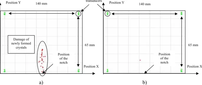
Figure 7: Micro-cracking map of a specimen after the pre-cracking phase; a) Result without filtering, b) Result with filtering in energy: events with an energy higher than 1000 aJ According to the same filtering criterion, new maps are obtained for aged specimens in order to locate the newly formed crystals micro-cracking. In a first analysis, they are performed during the reloading phase (in the pre-peak regime) until 18 µm crack mouth opening. Figure 8 presents the maps for a specimen aged in water and for a specimen aged in air, both during 10 weeks. It is noticeable that micro-cracks appear for the healed specimen in the region of the initial crack, while nearly no micro-cracks are detected for a non healed specimen. In one case, there is damage of crystals in the crack, and in the other case, there is only the re-opening of the existing crack, without any damage but with eventually some detected frictions. These results confirm that crystals have precipitated in the crack during storage in water, and they start being damaged in the pre-peak phase of reloading. The sudden decrease of the stiffness in the pre-peak regime is the consequence of this damage process.
a) b)
Figure 8: Micro-cracking maps, during the reloading phase (until 18 µm – pre-peak regime) of specimens aged for 10 weeks; (a) ageing in water, (b) ageing in air
140 mm 140 mm 65 mm 65 mm Position Y Position Y Position X Position X transducers Position of the notch Position of the notch transducers Position Y Position Y 65 mm 65 mm Position X Position X 140 mm 140 mm Position of the notch Position of the notch Damage of newly formed crystals
This result is confirmed by the analysis of the total number of detected acoustic events. The appearance of acoustic emission while fracturing is linked to the development of damage [12]. Figure 9 presents the cumulative number of detected acoustic events as a function of the crack mouth opening displacement, for the reloading of two healed specimens and two non healed specimens (specimens aged during 10 weeks).
0 100 200 300 400 500 600 700 800 0 5 10 15 20 25 30 healed specimen n°1 healed specimen n°2 non healed specimen n°1 non healed specimen n°2
C u mulativ e number of detec ted ac ous tic ev ents
Crack mouth opening displacement (µm)
Figure 9: Evolution of the cumulative number of detected acoustic events for healed specimens and non healed specimens, during reloading phase
So, we can see that in the case of healing, the development of damage appears sooner than for non healed specimens, which confirms the fact that new crystals are damaged in a first time during the reloading phase.
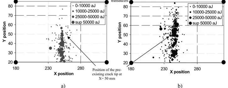
We can now consider, in a second analysis, a comparison during the reloading phase, not at the same CMOD, but at the same load level. Results at 90% of the peak load, in the post peak regime are analysed. Figure 10 represents the location maps in terms of energy. Points representing the micro-cracks are plotted according to their acoustic energy: the bigger the point, the more important the energy.
a) b)
Figure 10: Energy location maps at 90% of the peak load in the post peak regime; a) healed specimen, b) non healed specimen
transducers 20 30 40 50 60 70 80 180 230 280 X position Y position 0-10000 aJ 10000-25000 aJ 25000-50000 aJ sup 50000 aJ 20 30 40 50 60 70 80 180 230 280 X position Y position 0-10000 aJ 10000-25000 aJ 25000-50000 aJ sup 50000 aJ
Position of the pre-existing crack tip at
If we sum these energies for events located below and above the pre-existing crack tip (which is for height of 50 mm from the bottom face of the specimen), we can notice that nearly 100% of the acoustic energy dissipated until 90% of the peak load is located in the pre-existing crack, for the specimen which has been stored in water, although it is 50 % for a non healed specimen (acoustic events due to frictions or re-opening of micro-cracks). This result highlights the two regimes of damage for healed specimens: first we have damage of the newly formed crystals, and then continuation of the crack propagation. If we consider now the total energy dissipated, it is 50% less in the case of a healed specimen. This energy corresponds to the micro-cracking of the new crystals in the case of healing, and corresponds to the micro-cracking of healthy concrete in the case of non healing. We can thus consider that the mechanical properties of the new crystals should be less than those of healthy concrete.
4.2 SEM observations
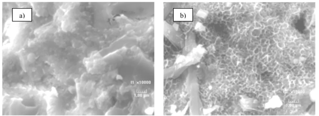
In order to complete our mechanical and acoustic results, and to explain what really happens in the crack, SEM observations are performed. The essential aim is to determinate the nature of the new crystals that have precipitated in the crack. The observations are performed on the crack surfaces after the reloading phase, and are completed by some qualitative analysis by energy dispersive spectrometry (EDS) technique. Figure 11 presents the typical observations for a non healed crack surface, and for a healed one, with an enlargement of 10000.
Figure 11: SEM observations on the crack surfaces of the studied concrete; a) crack without healing, b) crack with healing – Enlargement of 10000
The typical crack surface without healing shows a very dense microstructure, made of C-S-H gel. On the contrary, the observations carried out on the healed surface are totally different. We can thus see a particular structure formed by alveolar crystals. EDS tests are carried out on several places in these crystals and give the typical result which can be seen on figure 12.
Figure 12: Result of the energy dispersive spectrometry analysis on the alveolar crystals on the healed crack surfaces
This analysis reveals the typical composition of alveolar C-S-H. We can thus give some new explanations about the mechanical behaviour of healed specimens. Indeed, the fact that C-S-H have clearly precipitated in the crack explains the recovery of stiffness. Nevertheless, the special structure of these new C-S-H, in comparison with the very dense structure of hardened concrete, can not permit to recover the specimen strength. It is in fact difficult to build in the crack, the complex structure, which gives its strength to concrete, and especially all the links between C-S-H.
5. SELF HEALING FOR USUAL CONCRETES
After having investigated in details the phenomenon of self healing of cracks on an ultra high performance concrete, this research work is extended to usual concretes, and especially to the influence of composition on the phenomenon.
The same mechanical tests are conducted on four different concretes, including the pre-cracking phase, the ageing, and finally the reloading phase in order to characterize the mechanical behaviour of healed specimens. Concrete are designed in order to get exactly the same granular skeleton (with a ratio gravel/sand equal to 1.45), and to keep the paste volume constant (cement, water, and additions). Only the water/cement ratio varies form 0.3 to 0.5, and one of this four concrete includes silica fume. The mix design proportions are presented in table 1.
Table 1: Composition of the four concretes studied (for 1 m3)
Concrete 1 Concrete 2 Concrete 3 Concrete 4
W/C ratio 0.33 0.43 0.54 0.48 Gravel (kg) 1051.3 1051.3 1051.3 1051.3 Sand (kg) 722.7 722.7 722.7 722.7 Water (L) 156 177 193 174 Cement (kg) 476 410 360 366 Silica fume (kg) 0 0 0 36 Superplasiticizer (kg) 4 2 1 2 Chemical element Counts
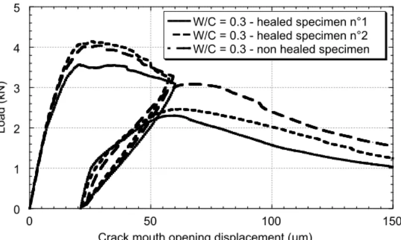
After casting, the prismatic specimens (dimensions 50x100x500 mm3) have been cured in water for 120 days. Young modulus (followed by the measurement of resonance frequency) and compressive strength are stable at the end of this curing time. They are then stored in a climate chamber at 20°C and 50% relative humidity, but are not thermally treated. The specimens are then pre-cracked under 3 points bending. The four concretes are less brittle than the ultra high performance one. So it is difficult to aim a residual crack width of 10 µm with a significant damage. It was so decided to aim a residual crack width in the order of 20 µm. The specimens are then totally immerged in water at 20°C and their mechanical behaviour is characterized after 10 weeks of ageing. The mechanical behaviour of non aged specimens is also characterized in comparison: specimens are pre-cracked and then immediately reloaded. Figure 13 presents the typical results obtained for specimens of concrete 1, pre-cracked at 20 µm and aged for 10 weeks, compared with the mechanical behaviour of a non healed specimen.
0 1 2 3 4 5 0 50 100 150 W/C = 0.3 - healed specimen n°1 W/C = 0.3 - healed specimen n°2 W/C = 0.3 - non healed specimen
Load (kN)
Crack mouth opening displacement (µm)
Figure 13: Mechanical behaviour of healed specimens (10 weeks) compared with mechanical behaviour of a non healed specimen, for concrete with W/C = 0.3
We could have represented the same result for the three other concretes. Qualitatively, we have exactly the same result: there is a very slight recovery of initial stiffness for healed specimens, and a very significant loss of flexural resistance, in comparison with non healed specimens. If we consider only the healed specimens, Figure 14 shows the average reloading curves (only the reloading part) for the four concretes, after 10 weeks of ageing. The curves display the ratio load applied on load at the unloading point of the pre-cracking phase, in order to be able to make comparisons.
0 0.2 0.4 0.6 0.8 1 0 50 100 150 200 W/C=0.3 W/C=0.4 W/C=0.5 W/(C+SF)=0.4
Load applied / Load at the unloading
point of the pre-cracking phase
Crack mouth opening displacement (µm)
Figure 14: Average mechanical behaviour of specimens from different concrete compositions during the reloading phase
We can thus notice that the influence of composition of concrete on the phenomenon of self healing is quite limited for our tests. It appears that the highlighted deterioration of strength is less important for concrete with low W/C ratio, and for concrete which includes silica fume. But, this loss of strength is quite surprising. And we certainly need more information to be able to explain this result. Nevertheless, a first explanation based on the structure of the hardened cement paste could be advanced. Indeed, for the ultra high performance concrete, anhydrous cement grain present in the microstructure can be fractured in their whole volume, so that cement is directly in contact with water and can reacts. On the contrary, for usual concretes, the crack is preferentially located in the interface between cement paste and aggregates, and the intrusion of water can deteriorate this zone (increase of porosity) and thus degrade the strength. We can also wonder if the residual crack widths are not just too big to have the formed crystals bridging the gap between the two faces of the crack. As a conclusion, this investigation of the self healing on usual concretes indicates that the role of self healing on the mechanical properties of such concrete is limited. Further investigations, with, for instance, ageing conditions in air with high relative humidity and longer ageing times, could complete this part of the research work.
6. CONCLUSION
In the first part of this research work, the results of an experimental investigation on the mechanical behaviour of healed ultra high performance concrete specimens have been presented. After a controlled pre-cracking phase under three points bending, prismatic specimens are aged, in air or in water, during various durations ranging from 1 to 20 weeks. It appears that after storage in water exclusively, damaged beams tend to recover fast their initial global stiffness, and to improve slowly their flexural strength. These mechanical results are attributed to the phenomenon of self healing of crack. An acoustic emission analysis is then performed in order to confirm the precipitation of new crystals in the crack. Micro-cracking processes of healed specimens are thus investigated, and permit to locate the micro-cracking of these new crystals during the reloading phase of the mechanical tests. It also
shows the two phases of the cracking processes of healed concrete, including damage of newly formed crystals and continuation of the crack propagation. All these investigations are corroborated with microscopic observations, which shows that new C-S-H, with an alveolar structure different from those of C-S-H of normal hydration, have precipitated in the crack. The mechanical tests are then applied to four usual concretes. The influence of composition of concrete on the phenomenon is analysed. The mechanical results obtained are totally different from those get on the ultra high performance concrete. Indeed, storage in water tends to deteriorate the mechanical strength of the specimens, which can be explained by the very different microstructure of these concretes, compared with the ultra high performance one. Further investigations are needed in order to get complete conclusions for usual concretes. REFERENCES
[1] Neville, A., “Autogenous healing – A concrete miracle?”, Concrete International,
November 2002
[2] Edvardsen, C., “Water permeability and autogenous healing of cracks in concrete”, ACI Materials Journal, Vol 96, N°4, July-August 1999, pp. 448-454
[3] Hearn, N., “Self-sealing property of concrete – Experimental evidence”, Materials and Structures, Vol 30, August-September 1997, pp. 404-411
[4] Hearn, N., “Self–sealing, autogenous healing and continued hydration: what is the difference?” Materials and Structures, Vol 31, October 1998, pp 563-567
[5] Reinhardt, H.W. and Joos, M., “Permeability and self-healing of cracked concrete as a function of temperature and crack width”, Cement and Concrete Research, Vol 33, N°7, pp. 981-985, 2003
[6] Jacobsen, S. and Sellevold, E., “Self healing of high strength concrete after deterioration by freeze/thaw”, Cement and Concrete Research, Vol 26, N°1, pp. 55-62, 1996
[7] Pimienta, P. and Chanvillard, G., “Retention of the mechanical performances of Ductal specimens kept in various aggressive environments”, Fib - Symposium 2004, April 26-28, Avignon, France
[8] Loukili, A., Richard, P. and Lamirault, J., “A study on delayed deformations of an ultra high strength cementitious material”, ACI, SP179-59, Recent Advances in Concrete Technology, Vol 179, 1998
[9] Acker, P., "Micromechanical analysis of creep and shrinkage mechanisms", Creep, Shrinkage and Durability Mechanics of Concrete and other quasi-brittle Materials, F.-J. Ulm, Z.P. Bažant, F.H. Wittmann editors, Elsevier, Oxford UK, Aug. 2001
[10] Acker, P., “Swelling, shrinkage and creep: a mechanical approach to cement hydration”, Concrete Science & Engineering, Vol 37, pp. 237-243, 2004
[11] Otsuka, K., Date, H., “Fracture process zone in concrete tension specimen”, Engineering Fracture Mechanisms, Vol 65, Issues 2-3, January 2000, pp. 111-131
[12] Landis, E. N., “Micro-macro fracture relationships and acoustic emissions in concrete”, Construction and Building Materials, vol 13, 1999, pp. 65-72