HAL Id: hal-00451907
https://hal.archives-ouvertes.fr/hal-00451907
Submitted on 26 Jun 2019
HAL is a multi-disciplinary open access
archive for the deposit and dissemination of
sci-entific research documents, whether they are
pub-lished or not. The documents may come from
teaching and research institutions in France or
abroad, or from public or private research centers.
L’archive ouverte pluridisciplinaire HAL, est
destinée au dépôt et à la diffusion de documents
scientifiques de niveau recherche, publiés ou non,
émanant des établissements d’enseignement et de
recherche français ou étrangers, des laboratoires
publics ou privés.
Mechanisms
Sébastien Briot, Ilian Bonev
To cite this version:
Sébastien Briot, Ilian Bonev. Singularity Analysis of Zero-Torsion Parallel Mechanisms. IEEE/RJS
International Conference on Intelligent Robots and Systems, Sep 2008, Nice, France. �hal-00451907�
equally spaced plane intersecting at one line. The computation of the singularity loci is based on the degeneracy of the system of screws applied on the platform by the legs. The whole study is based on the use of a special orientation representation, previously introduced under the name of Tilt-and-Torsion angles. This representation is briefly introduced. Then the interdependence between the Cartesian coordinates of the general class of parallel mechanisms is derived. Finally, the singularity loci are derived and the size of the workspace taking into account all singular configurations is shown.
I. INTRODUCTION
OR the last few decades, parallel mechanisms are increasingly being used and studied. Even if most works on parallel mechanisms were focused on 6-degrees-of-freedom (DOFs) mechanisms (mainly hexapods), recently, more interest has been paid to mechanisms with less than 6 DOFs. The most popular of these mechanisms belong undoubtedly to the group of 3-DOF symmetric parallel mechanisms whose mobile platform is attached to three identical legs via spherical joints (Fig. 1). The legs constrain the centers of the spherical joints to move in three equally spaced vertical planes intersecting at a common line. These mechanisms will be referred to as 3-[PP]S ones1.
There is abundant literature on this group of mechanisms, studying their kinematics, singularity analysis and design. For example, a 3-PPS parallel mechanism was proposed in [1] (Fig. 1a), the 3-RPS architecture (Fig. 1b) was analyzed in [2-6], two different 3-PRS designs were studied in [7] (Fig. 1c) and [8] (Fig. 1d), the latter design being best known through the Z3 Head by DS Technologie [9], and finally a 3-RRS robot was investigated in [10]. Of all these publications, only [3] seems to identify the exact nature of the interdependence of the orientation parameters and its geometric significance. To fill this important gap, the second author studied the kinematic geometry of 3-[PP]S parallel mechanisms and showed clearly their motion pattern [11].
Manuscript received January 25, 2008. This work was supported by FQRNT and the French Ministère des Affaires étrangères et européennes.
Sébastien Briot and I.A. Bonev are with the Department of Automated Manufacturing Engineering of the École de technologie supérieure (ÉTS), Montreal, QC, Canada H3C 1K3 (phone: 8403; fax: 514-396-8595; e-mails: [email protected], [email protected]).
1 It is common to denote parallel mechanisms by using the symbols P, R,
and S, which stand respectively for prismatic, revolute and spherical joint. When a joint is actuated, its symbol is underlined. In this paper, we also use
[PP] to denote any combination of joints that allows 2-DOF planar motion.
(a) a 3-PPS parallel mechanism (b) a 3-RPS parallel mechanism
(c) a 3-PRS parallel mechanism (d) a 3-PRS parallel mechanism Fig. 1. Examples of 3-DOF 3-[PP]S parallel mechanisms
In this paper, we use a special orientation representation to obtain simplified relations for the singularity analysis of these mechanisms. This orientation representation was recently applied to the derivation of the closed-form direct kinematics of the mechanisms shown in Fig. 1(a-c)[12]. It was shown that this representation considerably simplify the expressions of the direct kinematics of such mechanisms. Thus, in the next section, we describe briefly this orientation representation and use it in Section 3 to derive the simple interdependence between the orientation angles and the position of the platform of a general 3-[PP]S parallel mechanism. Then, in Section 4, we present the expression of the singularity loci of four 3-[PP]S parallel mechanisms, namely the 3-PPS design (Fig. 1a), the general 3-RPS design (Fig. 1b), and two common 3-PRS designs (Fig. 1c and 1d). We also analyze the size of the singularity-free workspace of these structures, as a function of the design parameters, taking into account all singular configurations. Finally, conclusions are drawn in Section 5.
Fig. 2. The successive rotations of the T&T angles: (a) tilt, (b) torsion
II. ORIENTATION REPRESENTATION
A novel three-angle orientation representation, later called the Tilt-and-Torsion (T&T) angles, was proposed in [13] in 1999, in conjunction with a new method for computing the orientation workspace of symmetric spatial parallel mechanisms. It was shown that the T&T angles take full advantage of a mechanism’s symmetry. These angles were also independently introduced in [14] and [15] in 1999. Later, it was found out that the angles had been proposed in [16] in 1984 under the name halfplane-deviation-twist angles. The author of that reference proposed the set due to its indisputable advantages in modeling the limits of human body joints. Yet, again in 1999, these angles were proposed independently in [17] as a new standard in modeling angular joint motion, and particularly that of the spinal column’s vertebra. These angles are also used for computer animation of articulated bodies, known as the swing-and-twist representation. In [11], the advantages of the T&T angles in the study of spatial parallel mechanisms were further demonstrated. It was shown that there is a class of 3-DOF mechanisms that have always a zero torsion, that we now call zero-torsion parallel mechanisms. Furthermore, it was demonstrated in [18] and [19] that the workspace and singularities of symmetric spherical parallel mechanisms are best analyzed using the T&T angles.
The T&T angles are defined in two stages—a tilt and a torsion. This does not, however, mean that only two angles define the T&T angles but simply that the axis of tilt is variable and is defined by another angle. In the first stage, illustrated in Fig. 2a, the body frame is tilted about a horizontal axis, a, at an angle θ, referred to as the tilt. The axis a is defined by an angle φ, called the azimuth, which is the angle between the projection of the body z’ axis onto the fixed xy plane and the fixed x axis. In the second stage, illustrated in Fig. 2b, the body frame is rotated about the body z’ axis at an angle σ, called the torsion.
For space limitations, we will omit the otherwise quite interesting details of the derivation process (see [11]), and write directly the resulting rotation matrix of the T&T angles, which is
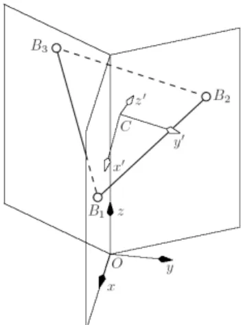
Fig. 3. Kinematic geometry of a general 3-[PP]S parallel mechanism
− + − + − − − = − − − − − − − − − − θ φ σ θ φ σ θ θ φ φ σ φ φ σ θ φ φ σ φ φ σ θ φ θ φ φ σ φ φ σ θ φ φ σ φ φ σ θ φ σ θ φ c s s c s s s c c s c s s c c c s s c c s s c c s s c c c ) , , ( R , (1)
where cφ= cos φ, sφ= sin φ, cθ= cos θ, sθ= sin θ, cσ−φ= cos(σ−φ) and sσ−φ = sin(σ−φ).
One of the properties of three-angle orientation representation is that a given orientation can be represented by at least two triplets of angles. In our case, the triplets {φ, θ, σ} and {φ ± π, −θ, σ} are equivalent. To avoid this and the representational singularity at θ = π (which is hardly achieved by any parallel mechanism), we set the ranges of the azimuth, tilt, and torsion as, respectively, φ ∈ (−π; π], θ ∈ [0, π), and σ ∈ (−π; π]. Then, probably the most valuable property of the T&T angles is that for the ranges just defined, the angles (φ, θ, σ) can be represented in a cylindrical coordinate system (r, φ, h) through a one-to-one mapping. In other words, any orientation (except a θ = π one) corresponds to a unique point within a cylinder in the cylindrical coordinate system, and vice versa. The reason is that the T&T representational singularity at θ = 0 is of the same nature as the singularity of the cylindrical coordinate system occurring at zero-radius (r = 0).
III. KINEMATIC GEOMETRY OF 3-[PP]SPARALLEL
MECHANISMS
As already mentioned, each leg of a 3-[PP]S parallel mechanisms has a 2-DOF planar chain, followed by an S joint. The vertical planes in which the three equidistant S joints move are intersecting at a common line at 120° (Fig. 3). Now, let O – xyz be the base reference frame, such that its z axis coincides with the common line of the three planes, and its x axis lies in the plane of leg 1.
For brevity, let the three equidistant S joint centers, denoted by Bi, lie on a circle of radius 1, i.e.,
T CB [1,0,0] ' 1= r , (2) T CB [cos(2 /3),sin(2 /3),0] ' 2= π π r , (3) T CB [cos(4 /3),sin(4 /3),0] ' 3= π π r , (4)
constrain the S joint centers in the three vertical planes: 0 1 = OB y , (6) 0 ) 3 / 2 sin( ) 3 / 2 cos( 2 2 − OB = OB x y π π , (7) 0 ) 3 / 4 sin( ) 3 / 4 cos( π yOB3− π xOB3 = , (8) Since z is obviously an independent coordinate, it is of no surprise that, after substitution of yOB1, xOB2, yOB2, xOB3, and yOB3 from (5), none of the above three equations contains that variable: 0 3 , 1 = +q y , (9) 0 2 1 2 3 3 , 2 = + − − x y q , (10) 0 2 1 2 3 3 , 3 = + − y q x , (11)
where q1,3, q2,3, and q3,3 are functions of the three T&T
angles. Therefore, in order to have a solution for x and y, the three linear equations must be linearly dependent. Obviously, any two of these equations are linearly independent. Hence, for any feasible orientation of the mobile platform, there is a unique solution for {x, y}.
Let Q be the coefficient matrix for the above three equations, i.e., 1,3 2,3 3,3 0 1 3 1 2 2 3 1 2 2 q q q = − − − Q . (12)
For these equations to be linearly dependent, the matrix Q should be singular, i.e.,
(
cos 1)
0 sin 4 3 3 detQ= σ θ+ = . (13)Disregarding θ = π, (13) leads us to the only remaining possibility: σ = 0 or σ = π. If we substitute σ = 0 or σ = π in (9–11), and solve any two of them, we obtain the following for the feasible motion of the mobile platform center:
(
cos 1)
2 cos 2 1 δ − = φ θ x , (14)(
cos 1)
2 sin 2 1 δ − − = φ θ y , (15)where δ = 1 for σ = 0 and δ = −1 for σ = π. These two modes of operation are separated by a constraint singularity, which
IV. SINGULARITY LOCI OF 3-[PP]SPARALLEL MECHANISMS
Among the abundant literature devoted to 3-[PP]S mechanisms, only a few papers deal with the subject of singularities [5, 6, 21, 22]. Among these papers, references [5, 6] present the singularity analysis of a 3-RPS structure. However, in both papers, the obtained expressions are numerous and complicated due to the use of general Euler angles and are basically not exploitable. Reference [21] presents a short singularity analysis of the 3-PRS structure, but gives no expressions characterizing the singular configurations. Finally, reference [22] presents a geometric approach to finding Type 2 singularities of three-legged parallel mechanisms.
In this section, we will analyze the Type 2 singularities of four 3-[PP]S parallel mechanisms, namely the 3-PPS design, proposed in [1] (Fig. 1a), the general 3-RPS design (Fig. 1b), and the two 3-PRS designs proposed in [7] and [8] (Fig. 1c and 1d). To realize this analysis, we will study the degeneracy of a 6-dimensional matrix composed of the screws applied on the platform by the moving legs and will give for the first two mechanisms (the 3-PPS and the 3-RPS) simple analytical expressions characterizing the singularity loci obtained by the use of the T&T angles. We will show for the other two mechanisms that the singularity loci can be represented by a polynomial of high order (of degree 24). Moreover, for each mechanism, the maximal reachable workspace taking into account the singular configuration will be represented as a function of the design parameters.
A. Singularity Loci of 3-PPS Parallel Mechanisms Referring to Fig. 4, the directions of the actuated prismatic joints are vertical, while the directions of the passive prismatic joints are horizontal.
Each leg applied two screws Ri1 and Ri2 on the platform.
Thus, as shown on Fig. 4, for this manipulator, Ri1 and Ri2
are two forces located at point Bi and directed along the vertical axis z and perpendicular to the plane of the legs, respectively. The system of screws degenerates if the determinant of matrix J, of which the lines are composed of the coordinates of the screws Rij (j = 1, 2), vanishes. After
simplification, this determinant can be written as:
(
θ)
θ 1 cos cos 8 27 det J= + , (17)Fig. 4. Schematics of a 3-PPS parallel mechanism
Disregarding θ = π, (13) leads us to the only remaining possibility for Type 2 singularities: θ = ±π/2.
Thus, for any 3-PPS parallel manipulator, the workspace is bounded by the orientation θ = ±π/2 of the platform, for any altitude z and angle φ.
B. Singularity Loci of 3-RPS Parallel Mechanisms As shown in Fig. 5, for this mechanism, Ri1 and Ri2 are
two forces located at point Bi, the first directed along the line AiBi and the second perpendicular to the plane of the legs. The system of screws degenerates if:
0 ) 3 cos( ) 3 ( cos det 1 0 2 2 + + = =c φ c φ c J , (18)
where c0, c1 and c2 depend on angle θ, on the altitude z of the
center of the platform and on the radius Rb of the circumcircle of the base,
(
)(
)
3 2 1 cos cos 1 16 27 − + = z θ θ c ,(
)
(
)
(
1)(
2 ( 1)( 4 1) 3)
64 27 ) 4 8 12 ( ) 1 3 ( 1 64 27 2 2 1 − − + − + − − + + + + + − − − = b b b R c c R c s R c z c c c c s c θ θ θ θ θ θ θ θ θ θ ,(
)
(
)
(
1)(
4 ( 1)( 2 ))
32 27 4 ) 3 4 ( 1 32 27 2 2 0 b b c c R R c z z c c c c c z c + − + − + + − − − + − = θ θ θ θ θ θ θ θ .Therefore, it is quite simple to find the exact expression of the singularity loci expressing angle φ as a function of the other parameters: 3 2 2 4 cos 3 1 2 0 2 2 1 1 1 π φ n c c c c c + − ± − = − , n = 0, 1, 2… (19)
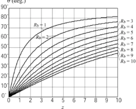
Fig. 6 shows an example of singularity loci in the workspace of a 3-RPS parallel mechanism with Rb = 1.3 for z = 1. We can now analyze the size of the workspace represented by the maximal reachable angle θ for any angle φ as a function of the altitude of the platform and of the design parameters Rb (Fig. 7).
Fig. 5. Schematics of a 3-RPS parallel mechanism
Fig. 6. Singularity loci in the workspace of a 3-RPS parallel mechanism with Rb = 1.3 for z = 1
Fig. 7. Maximal reachable angle θ for any angle φ
The approach used to compute the maximal reachable angle θ can be described as follows. First, we fix the design parameter Rb and discretize the variable space {z, φ, θ}. Then, for a given set of variables {z, φ} and starting from θ = 0, we observe the evolution of the sign of the determinant of matrix J when θ is varying. We met a singularity if, between two values of θ, the sign of det J varies. Thus, we stop the procedure and retain the value θm of angle θ just before crossing the singular configuration. Then, we redo this algorithm for another value of angle φ. When this procedure has been realized for any angle φ, we
1 2 3 2 1 3 3 1 2 1 1 2 2 3 3 det 0 A A A B B B C = Γ Γ + Γ Γ + Γ Γ + Γ + Γ + Γ + = J , (20) for the mechanism of Fig. 1c, with
) ( ) 1 ( ) 1 ( ) 1 ( ) 1 ( 8 9 ) ( 1 Aφ cφ cφ+ cθ cθ+ z cφsθ A = = − − − , ) 3 / 2 ( 2 =Aφ− π A ,A3= A(φ+2π/3), ) 3 4 3 4 4 ( ) 4 7 4 1 64 9 ) ( 2 2 2 3 2 2 2 1 θ θ θ θ φ θ φ θ φ θ φ φ φ s s z + c + s z c s c c c + c c ( c B B − + − − − = = , ) 3 / 2 ( 2 =Bφ− π B ,B3=B(φ+2π/3), ) 4 3 ( ) 1 ( 32 27 2 3 3 3 z z+ s c s + c c C=− θ θ − θ φ− θ , ) ( 1=±Γφ Γ , where Γ(φ)=2 L2−z2+2cφsθ z−cφ2sθ2 ) 3 / 2 ( 2 =±Γφ− π Γ ,Γ3 =±Γ(φ+2π/3), and, 0 det 3 3 2 2 1 1 2 1 3 3 1 2 3 2 1 3 2 1 = ∆ + ∆ + ∆ + ∆ ∆ + ∆ ∆ + ∆ ∆ + ∆ ∆ ∆ = F F F E E E D J , (21)
for the mechanism of Fig. 1d, with ) 1 ( 6 27 + c c D=− θ θ , ) 2 3 4 4 ( ) 1 4 7 4 ( 64 9 ) ( 2 2 2 2 1 b R + c + +c c c + c c + c c c s E E − − − − = = φ θ θ φ θ φ φ φ φ θ φ , ) 3 / 2 ( 2 =Eφ− π E ,E3 =E(φ+2π/3), 2 2 4 2 1 2 2 2 2 9 ( ) 4 ( 2 1) 4 ( 5 8 2 2 3) 2
(
)
φ θ φ θ θ φ θ θ θ θ θ φ = = − + + − + + − − + − + b b b b F F s s c c c c c c R c R c R c R , ) 3 / 2 ( 2 =F φ− π F ,F3 =F(φ+2π/3), ) ( 1 =±∆φ ∆ , where 2 / 1 2 2 4 2 ) 4 / 39 4 ) 3 2 12 ( ) 3 8 30 ) 3 ( 16 ( ) 28 3 16 ( 3 3 4 ( ) ( − + − + − − + − − = ∆ b b b b R R c R R c + + L φ φ φ ) 3 / 2 ( 2 =±∆φ− π ∆ ,∆3 =±∆(φ+2π/3).(a) for the mechanism of Fig. 1c, for L = 1.3 and z = 0.5
(b) for the mechanism of Fig. 1d, for L = 1 and Rb = 1.3
Fig. 8. Singularity loci in the workspace of the 3-PRS parallel mechanisms under study
(a) for the mechanism of Fig. 1c
(b) for the mechanism of Fig. 1d Fig. 9. Maximal reachable angle θ for any angle φ
In these expressions, Γi and ∆i are radicals depending on the working mode (solution of the inverse kinematics) of the mechanism. Thus, Type 2 singularity loci are much more complicated to determine due to the existence of these terms. Indeed, to eliminate all radicals in the equation det J, the latter should be rearranged and squared three times, using a similar method as that proposed in [23] for the 3-RRR planar parallel robot. The equation resulting after these operations corresponds to all eight working modes.
Since this procedure cannot be performed symbolically, we firstly assign random integer values to the coefficients θ, Rb, L, and z. Then, we eliminate the radicals by rearranging terms and squaring three times the equations. Finally, as the system is symmetrical, it is possible to rearrange the obtained polynomial in cos φ and sin φ into a polynomial in cos 3φ. Finally, it can be observed that the obtained polynomials are of degree 16 for the mechanism of Fig. 1c, and of degree 24 for the mechanism of Fig. 1d.
Fig. 8 shows examples of singularity loci in the workspace of the 3-PRS parallel mechanisms under study.
Finally, we analyze the size of the singularity-free workspace represented by the minimum of all maximal reachable angles θ for any angle φ, without reaching a singularity, as a function of the altitude of the platform and of the design parameters Rb and L (Fig. 9a and 9b). We use an algorithm similar to that used for the 3-RPS parallel mechanism. It can be observed that:
- for the mechanism of Fig. 1c, the size of the singularity-free workspace increases with the altitude of the platform; moreover, for L close to 2 and for a high altitude z, the value of angle θ reaches 90°. - for the mechanism of Fig. 1d, the size of the
singularity-free workspace increases when L increase and Rb decrease; moreover, for Rb close to 1, the value of angle θ reaches 80°.
V. CONCLUSIONS
We presented in this paper yet another example of the advantages of using Tilt-and-Torsion angles for the analysis of 3-DOF zero-torsion parallel mechanisms. In particular, we proposed, for the first time, simple expressions for the singular configurations of four different zero-torsion mechanisms, namely a 3-PPS design, the general 3-RPS design, and two 3-PRS design. Furthermore, we analyzed the maximal singularity-free workspace of these mechanisms as a function of their design parameters. It should now be clear that so-called zero-torsion parallel mechanisms must be analyzed using Tilt-and-Torsion angles only.
REFERENCES
[1] Liu, X.-J., Pruschek, P., and Pritschow, G., “A new 3-DoF parallel mechanism with full symmetrical structure and parasitic motions,”
Proceedings of the Intelligent manipulation and Grasping International Conference, Genova, Italy, pp. 389–394, 2004.
[2] Lee, K.-M., and Shah, D.K., “Kinematic analysis of a three-degree-offreedom in-parallel actuated manipulator,” IEEE Journal of
Robotics and Automation, Vol. 4, No. 3, pp. 354–360, 1988.
[3] Buruncuk, K., and Tokad, Y., “On the kinematics of a 3-DOF Stewart platform,” Journal of Robotic Systems, Vol. 16, No. 2, pp. 105–118, 1999.
[4] Kim, H.S., and Tsai, L.-W., “Kinematic synthesis of a spatial 3-RPS parallel manipulator,” ASME Journal of Mechanical Design, Vol. 125, pp. 92–97, 2003.
[5] Liu, C.H., and Cheng, S., “Direct singular positions of 3RPS parallel manipulators,” ASME Journal of Mechanical Design, Vol. 126, pp. 1006–1016, 2004
[6] Sokolov, A., and Xirouchakis, P., “Singularity analysis of a 3-DOF parallel manipulator with R-P-S joint structure,” Robotica, Vol. 24, No. 1, pp. 131–142, 2006.
[7] Carretero, J.A., Nahon, M.A., and Podhorodeski, R.P., “Workspace analysis and optimization of a novel 3-DOF parallel manipulator,”
IEEE Journal of Robotics and Automation, Vol. 15, No. 4, pp. 178–
188, 2000.
[8] Tsai, M.-S., Shiau, T.-N., Tsai, Y.-J., and Chang, T.-H., “Direct kinematic analysis of a 3-PRS parallel mechanism,” Mechanism and
Machine Theory, Vol. 38, No. 1, pp. 71–83, 2003.
[9] Wahl, J., “Articulated tool head,” WIPO Patent No. WO 00/25976, 2000.
[10]Li, J., Wang, J., Chou, W., Zhang, Y., Wang, and Zhang, Q., “Inverse kinematics and dynamics of the 3-RRS parallel platform,”,
Proceedings of the IEEE International Conference on Robotics and Automation, Seoul, Korea, pp. 2506–2511, 2001.
[11]Bonev, I.A., Zlatanov, D., and Gosselin, C.M., “Advantages of the modified Euler angles in the design and control of PKMs,” Parallel
Kinematic Machines International Conference, Chemnitz, Germany,
pp. 171–188, 2002.
[12]Bonev, I.A., “Direct kinematics of zero-torsion parallel mechanisms,”
Proceedings of the IEEE International Conference on Robotics and Automation, Pasadena, California, USA, May 19–23, 2008.
[13]Bonev, I.A., and Ryu, J., “Orientation workspace analysis of 6-DOF parallel manipulators,” Proceedings of the ASME 1999 Design
Engineering Technical Conferences, Las Vegas, NV, USA, 1999.
[14]Huang, T., Wang, J., and Whitehouse, D.J., “Closed form solution to workspace of hexapod-based virtual axis machine tools,” Journal of
Mechanical Design, Vol. 121, pp. 26–31, March 1999.
[15]Wang, Y., “Workspace analysis of a novel closed-chain manipulator,”
Thesis, Case Western Reserve Univ., Cleveland, OH, USA, 1999.
[16]Korein, J.U., A Geometric Investigation of Reach, MIT Press, 1984. [17]Crawford, N.R., Yamaguchi, G.T., and Dickman, C.A., “A new
technique for determining 3-D joint angles: The tilt/twist method,”
Clinical Biomechanics, Vol. 14, No. 3, pp. 153–165, 1999.
[18]Bonev, I.A., and Gosselin, C.M., “Singularity loci of spherical parallel mechanisms,” Proceedings of the IEEE International Conference on
Robotics and Automation, Barcelona, Spain, pp. 2968–2973, 2005.
[19]Bonev, I.A., and Gosselin, C.M., “Analytical determination of the workspace of symmetrical spherical parallel mechanisms,” IEEE
Transactions on Robotics, Vol. 22, No. 5, pp. 1011–1017, 2006.
[20]Zlatanov, D., Bonev, I.A., and Gosselin, C.M., “Constraint singularities of parallel mechanisms,” Proceedings of the IEEE
International Conference on Robotics and Automation, Washington,
DC, USA, pp. 496–502, 2002.
[21]Pond G., and Carretero, J., “Singularity analysis and workspace optimization of the inclined PRS manipulator,” Proceedings of the
2004 CCToMM M3 Symposium, 2004 CSME Forum, London,
Ontario, Canada, June 1–4, 2004.
[22]Ebert-Uphoff, I., Lee, J.-K., and Lipkin, H., “Characteristic tetrahedron of wrench singularities for parallel manipulators with three legs”, IMechE Journal of Mechanical Engineering Science
(Part C), Special issue on Spatial Mechamisms, Vol. 216, No. C1,
pp. 81–93, 2002.
[23]Bonev, I. A., and Gosselin, C. M., ‘‘Singularity Loci of Planar Parallel Manipulators with Revolute Joints,’’ Proc. 2nd Workshop on
Computational Kinematics, Seoul, South Korea, pp. 291–299, May