HAL Id: hal-00451948
https://hal.archives-ouvertes.fr/hal-00451948
Submitted on 24 Jun 2019HAL is a multi-disciplinary open access
archive for the deposit and dissemination of sci-entific research documents, whether they are pub-lished or not. The documents may come from teaching and research institutions in France or abroad, or from public or private research centers.
L’archive ouverte pluridisciplinaire HAL, est destinée au dépôt et à la diffusion de documents scientifiques de niveau recherche, publiés ou non, émanant des établissements d’enseignement et de recherche français ou étrangers, des laboratoires publics ou privés.
Design and Prototyping of New 4, 5 and 6 Degrees of
Freedom Parallel Manipulators Based on the Copying
Properties of the Pantograph Linkage
Vigen Arakelian, Sébastien Briot, Sylvain Guegan, Jean Le Flecher
To cite this version:
Vigen Arakelian, Sébastien Briot, Sylvain Guegan, Jean Le Flecher. Design and Prototyping of New 4, 5 and 6 Degrees of Freedom Parallel Manipulators Based on the Copying Properties of the Pantograph Linkage. 36th International Symposium on Robotics, Nov 2005, Tokyo, Japan. �hal-00451948�
Design and Prototyping of New 4, 5 and 6 Degrees of Freedom
Parallel Manipulators Based on the Copying Properties
of the Pantograph Linkage
Vigen Arakelian, Sébastien Briot, Sylvain Guégan, Jean Le Flecher Département de Génie Mécanique et Automatique - L.G.C.G.M. EA3913
Institut National des Sciences Appliquées (I.N.S.A.) 20 avenue des Buttes de Coësmes, CS14315
F-35043 Rennes, France e-mail: vigen.arakelyan@insa-rennes.fr
ABSTRACT
In this paper, a new family of parallel manipulators called PAMINSA1 is proposed. The particularity of these manipulators is the decoupling of displacements in the horizontal plane from its translation along the vertical axis. The advantages of such an approach are discussed, and a prototype is presented. The positioning errors of the moving platform taking into account the elasticity of links are determined and the performances of such a design are shown.
1. INTRODUCTION
Mechanisms known as parallel manipulators are defined in the terminology for the mechanism and machine science [1] as the manipulator that controls the motion of its end-effector by means of at least two kinematic chains going from the end-effector towards the frame. Such a mechanical architecture divides the manipulated load between the several legs of the system and, as a result, each kinematic chain carries only a fraction of the total load. Such a structural architecture allows for the reduction of the mass of the movable links and for the use of less powerful actuators. However, in spite of these advantages, there are some drawbacks, for example, a limited workspace or a high coupling between the different kinematic chains.
The non-linearity of the static and dynamic models of the parallel manipulators is not attractive for industrial applications. That’s why in the last few years new structures of parallel architectures have been developed for the decoupling of the kinematic and dynamic input/output relationships [2-5]. The analysis of these schemes shows that, in most cases, fully decoupling is developed, i.e. the decoupling of the displacements about all the degrees of freedom of the platform. Despite rather-encouraging results, we would like to note that the fully-decoupled manipulators have drawbacks also, for example, a lack of stiffness or the increasing of the joint number. It is obvious that it is not easy to solve the problem of the full decoupling of the movements and to conserve the principal advantages of the parallel structures. That’s why we tried to find a compromise
1
PAMINSA: Parallel Manipulator of the I.N.S.A.
between the decoupling of the movements and the architectural particularity of the parallel structures. A new approach to the problem of the design of decoupled parallel manipulators.
An energetic analysis shows that the work of gravity applied on a point moving in the horizontal plane is equal to zero (the gravitational forces are always perpendicular to the displacements). But the work of the same force applied on a point moving along the vertical axis is other than zero (the gravitational forces are parallel to the displacements). This phenomenon is used in the design of the hand operated manipulators [6], in which the horizontal displacements of the payload are carried out manually and the vertical displacements are actuated. To design a new parallel architecture, we have applied this principle.
In our previous works [7-9] the study of a new 4-dof parallel manipulator with decoupled motions was developed.
In this paper we generalize the adopted approach for the family of such manipulators from 4 to 6 degrees of freedom, and we show the performances of the prototype of the PAMINSA with 4-degrees of freedom.
2. THE FAMILY OF PAMINSA MANIPULATORS The family of the PAMINSA manipulators is based on the copying properties of the pantograph linkage, which represents the kinematic chain between the fixed base of the manipulator and its end-effector. Thus each leg of the suggested manipulator is a pantograph linkage with two input parameters. This makes it possible to decouple the displacements between the horizontal plane and the vertical axis. In this manner, the displacements of the platform in the workspace are obtained by controlling the displacements of the input points of each leg.
Figure 1 (a) and (b) represent two different versions of the legs of the PAMINSA. For the represented cases, the input points are Ai and Bi and the output point is Ci. If the point Ai is displaced horizontally, we obtain a horizontal displacement of the point Ci. If the point Bi is displaced vertically, we obtain a vertical displacement of the point Ci.
The application of the pantograph linkage allows the development of a new family of manipulators with 4, 5
or 6 degrees of freedom. It is possible to have different architectures for the same degree of freedom, differentiated by the number of legs between the base and the platform of the manipulator, as well as its actuated joints. In this paper we have only presented the manipulators with 3 legs and we note PAMINSA-iDjL a PAMINSA with i degrees of freedom and j legs. It should be noted that it is possible to create PAMINSA manipulators with 2 legs. These types of PAMINSA are presented in our previous work [8].
(a)
(b)
Fig. 1. Two different versions of the legs of PAMINSA manipulators.
Table 1 shows different architectures of the PAMINSA with three legs. For the PAMINSA-4D3L, the points Ai are actuated on the horizontal plane by 3 motors Mi which control directly the rotation of the revolute joints Ri. The second possible version of this manipulator is the control of the translations in the prismatic pairs Si. For both versions the vertical displacements of the point Bi are controlled by only one actuator MV. Thus, the motors
Mi control the displacement of the platform on the horizontal plane and the motor MV controls the
displacement towards the vertical axis.
For the PAMINSA-5D3L, the rotations of the three legs allow the displacements of the platform in the horizontal plane. Points Bi of two of the three legs are linked to the same actuator and the third leg has an independent vertical actuation. The vertical translations are controlled
by the simultaneous vertical displacements of points Bi of the 3 legs. The orientation about two axes is obtained by the vertical displacements of the point Bi of the legs. The PAMINSA-6D3L is a manipulator with 6 degrees of freedom composed of 3 legs. The rotations of the three legs allow the displacements of the platform on the horizontal plane. The point Bi of each leg is controlled by an independent actuator. The vertical translations and the orientation of the platform are obtained as previously. However, in this case the platform can be oriented about three axes.
Advantages and possible applications of the PAMINSA.
The obvious advantages of the suggested manipulator architectures are the following:
- The decoupling of the control powers in two parts, making possible to raise an important payload to a fixed altitude by powerful actuators and then to displace it on the horizontal plane by less powerful actuators;
- A great accuracy in the horizontal positioning because the payload can be locked in the horizontal plane by mechanical architecture of the manipulator, as well as the use of the less powerful actuators for the generation of motions on the horizontal plane (it is obvious that the less powerful actuators with a small load are more accurate then the powerful actuators). - The simplification of the vertical control based on
linear input/output relationships (note that the vertical displacement of the platform is a copy of the linear displacement of the actuator multiplied by a magnification factor).
Each kind of PAMINSA has its advantages and can be used differently. For example, the PAMINSA with 4 degrees of freedom allows improving the positioning accuracy about the vertical axis because the structure is mechanically locked during the displacement on the horizontal plane. We estimate in the following sections of this paper the positioning errors for a fixed altitude due to the structure deformations. Moreover, it allows improving the positioning accuracy on the horizontal plane along the x and y axes, because the loads due to the gravitational forces of the payload on the actuators Mi (i=1, 2, 3) are insignificant (they are equal to zero
after the balancing of the pantograph linkages, see [9]). Such a design allows the fixation of an important load in a given altitude, then, positioning it on the horizontal plane by displacements towards two axes and the rotation about the vertical axis.
The PAMINSA with 5 degrees of freedom allows the carrying out of all previous displacements with an inclination angle ψ of the platform (fig.2). The angle of the inclination ψ can be defined as an angle between the normal Npl to the platform and the normal N of the plane xOy. Thus it is possible to move the platform on the
horizontal plane with any inclination relative to the horizontal plane. In this case the inclination is defined by the rotation of the point C1 about the line C2C3.
The PAMINSA with 6 degrees of freedom allows for any orientation of the platform about the z axis and the displacements of the platform on the horizontal plane. The angle of the inclination ψ can be defined as for the previous case but it can have any given value (i.e. any rotation about C1, C2 and C3 is possible).
Fig.2. The angle of the inclination ψ of the platform. We would like to note that for the whole versions of the PAMINSA, there is a decoupling between the displacements on the horizontal plane and the displacements towards the vertical axis.
The authors believe that the proposed manipulators could be used in industrial applications for the manipulation of heavy equipment with great positioning accuracy. Various fields are possible depending on the type of industrial application.
The possible application of the PAMINSA could also be micromechanics for high-accuracy tasks. Indeed, thanks to the magnification factor of the pantograph linkage, a great displacement of the vertical actuators Mv can be
transformed into the small displacements of the platform.
3. THE PROTOTYPE OF THE PAMINSA-4D3L We have developed in the I.N.S.A. of Rennes a prototype of PAMINSA-4D3L (Fig. 3). A short description of the developed manipulator is presented below.
Fig. 3. The prototype of PAMINSA-4D3L developed in the I.N.S.A. of Rennes.
This prototype is based on the scheme presented in table 1. The displacements on the horizontal plane are obtained by actuating the revolute joint Ri (Harmonic Drive motors connected with the legs by means of the toothed-belt transmission, Fig.4).
Fig. 4. Actuation system of each leg.
The actuator Mv which controls the linear displacement
of the vertical axes of the manipulator’s legs is a linear actuator and, for the developed prototype, the PARVEX motor system was chosen.
The pantograph linkage has been carried out with double rods in order to improve the stiffness of the mechanical system. It is obvious that for an industrial application it is attractive to create a pantograph with single links and more rigid.
Error analysis due to the elastic deformations of the mechanical structure.
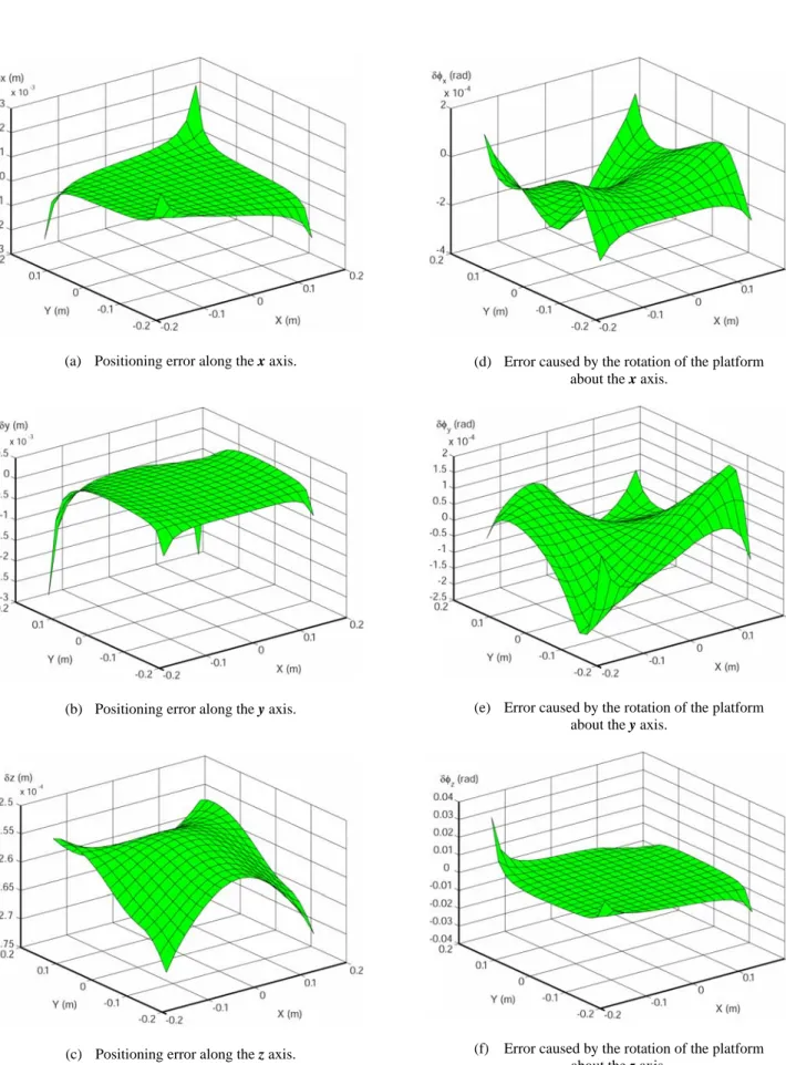
The stiffness of the developed prototype is studied taking into account the elasticity of the links of the pantograph linkages (the geometry and mass distribution parameters of the links are listed in Table 2). Two cases were examined on the CAD model (Fig. 5): the errors due to the deformations of the manipulator without any payload and with a load of 20 kg.
Figure 6 shows the positioning errors due to the deformations of the manipulator in the first case.
(a) Positioning error along the x axis.
(b) Positioning error along the y axis.
(c) Positioning error along the z axis.
(d) Error caused by the rotation of the platform about the x axis.
(e) Error caused by the rotation of the platform about the y axis.
(f) Error caused by the rotation of the platform about the z axis.
The analysis of the obtained results shows that the position in which the structure is less deformed is the central position. When the platform moves away from this position, the manipulator becomes less rigid and loses its accuracy. However, it is important to note that the absolute errors along the vertical axis are rather small (zmax= -0.25 mm and zmin= -0.27 mm). The difference between these two values is less than 20 µm. Thus, we can note that the suggested manipulator allows moving of the platform on horizontal plane with great accuracy. It should be also noted that the positioning errors do not depend on the elasticity of actuator systems. The gravitational forces are also vertical and do not have any action on the rotating actuators.
Fig. 7. Absolute positioning errors of the platform along the z axis with load of 20 kg (at altitude z=-0.6 m and with platform
orientation φ=0°).
With a payload of 20 kg applied on the platform, the absolute variations of the positions along the vertical axis are zmax= -1.22 mm and zmin= -1.36 mm (Fig. 7). The difference between these two values is less than 140 µm, which is small, taking into account that the pantograph links are hollow tubes with a thickness of 1.5 mm. It is obvious that positioning errors for the manipulator can be reduced with high stiffness links. Singular configurations.
The decoupling between the displacement on the horizontal plane and the displacement along the vertical axis allows the decoupling of the singularity analysis into parallel and serial singular configurations. Only the singular configurations of the planar projection of the suggested manipulator are represented below. It represents a planar 3-RPR parallel manipulator (Fig. 8). The singular configurations of the planar 3-RPR parallel manipulator [10, 11] appear if ρ1 or ρ2 or ρ3 is equal to 0, where ρi =OiCi represents the projection of the vector BiCi on the horizontal plane. In this case, the rotation of
one of the legs of the manipulator does not allow for the platform displacement on horizontal plane.
Another kind of singular configurations appears when
the orientation angle of the platform is equal to:
) / arccos(Rn Rb
± =
φ or if the platform centre is located
on a circle centred on point O with radius: φ cos 2 2 2 n b b n R R R R R= + − ,
where Rb is the base radius and Rn is the platform radius.
Fig. 8. Projection of the PAMINSA-4D3L on the horizontal plane. Workspace.
The designed prototype has the following characteristics: - Platform radius Rn = 100 mm,
- Base radius Rb = 350 mm, - Length DiCi = 630 mm, - Length AiDi = 420 mm,
- Magnification factor of the pantograph linkage k= 3, - Point Ai can move on the prismatic joint from a
distance to the vertical axis of the pantograph between 50 mm and 300 mm,
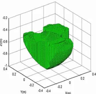
- The angle between the links AiDi et DiCi of the pantograph linkage is defined from 30° to 150°. The workspace of the developed prototype is shown in Fig.9. This is the total workspace in which there are singular configurations. The physical interpretation of a singularity in kinematics refers to those configurations in which the number of degrees of freedom of the mechanical structure changes instantaneously, either the manipulator gains some additional, uncontrollable degrees of freedom, or loses some degrees of freedom. Thus the workspace without the singular configurations is smaller. In order to eliminate the singular configurations, we think that it is reasonable to add two complementary linear actuators. It is important to note that these linear actuators will also be less powerful taking into account that the loads on the actuators which generate the displacements on the horizontal plane are very small (quasi-zero).
of the manipulator workspace without the singular configurations, is the optimal location of the frame’s leg joints. In the developed prototype the legs are located symmetrically and this assemblage of the legs is not efficient. Such a disposition of legs was selected for further study of the singularity in dynamics. It seems that there can be a more efficient assemblage with an asymmetric location of legs, for example, one leg on one side and two legs on the other side of the platform.
Fig. 9. Workspace of the developed prototype for a fixed orientation angle of the platform equal to 0°.
The space limitation of this paper did not permit the discussion of the optimal disposition of legs of the PAMINSA manipulators. In the future, we will make all possible efforts to provide a more detailed discussion regarding this problem.
4. CONCLUSIONS
In this paper, we have proposed a new family of parallel manipulators, in which the movements on the horizontal plane and the translations along the vertical axis are decoupled. Three types of such a decoupled manipulator with 4, 5 and 6 degrees of freedom are proposed. They are called PAMINSA and are divided into three groups. Each group has its advantages, which are discussed. The suggested structural architecture allows the application of the linear control of the vertical displacements and the cancellation of the loads on the actuators due to the gravitational forces during the displacements of the platform on the horizontal plane. The obtained results have shown that such design ensures a great absolute
accuracy of the manipulator towards the vertical axis of the platform.
Finally, it should be noted that the patent concerning of the PAMINSA manipulators is pending and additional information is available upon request.
REFERENCES
[1] Terminology for the mechanism and machine science, Mechanism and Machine Theory, 38, 597-605 (2003).
[2] Kong, X. & Gosselin, C. M. A Class of 3-DOF Translational Parallel Manipulator with Linear Input-Output Equations. Workshop on Fundamental Issues and Future Research for Parallel Mechanisms and Manipulators, pp. 25-32. Quebec City, Quebec, Canada (2002).
[3] Gosselin, C. M., Kong, X., Foucault, S., & Bonev, I. A. A Fully Decoupled 3-DOF Translational Parallel Mechanism. PKM International Conference, pp. 595-610. Chemnitz, Allemagne (2004).
[4] Carricato, M. & Parenti-Castelli, V. A Novel Fully Decoupled 2-DOF Parallel Wrist. The International Journal of Robotics Research, 23, N°6, 661-667 (2004). [5] Bouzgarrou, B. C., Fauroux, J. C., Gogu, G. & Heerah, Y. Rigidity Analysis of T3R1 Parallel Robot with Uncoupled Kinematics. ISR-2004. Paris, France (2004)
[6] Arakelian V. The history of the creation and development of hand-operated balanced manipulators. Proceedings of the HMM2004, Kluwer Academic Publishers, 2004.
[7] Briot S., Maurine P., Guégan S. & Arakelian V. Le PAMINSA : un nouveau manipulateur d’architecture parallèle aux mouvements découplés. Proceedings of the 17-ème Congrès Français de Mécanique, Troyes, France, August 29 - September 2 (2005).
[8] Arakelian V. & Briot S. A New Decoupled Parallel Manipulator with Four Degrees of Freedom. Proceedings of the 20th Canadian Congress of Applied Mechanics, Montreal, May 20 June 2, pp.415-416 (2005).
[9] Arakelian V., Guegan S. & Briot S. Static and Dynamic Analysis of the PAMINSA, Proceedings of the ASME 2005 IDETC/CIE Conference, Long Beach, USA, September 24-28 (2005).
[10] Gosselin C. M. & Angeles J. Singularity analysis of closed-loop kinematic chains. IEEE Transactions on Robotics and Automation, 6(3), 281-290 (1990).
[11] Bonev I., Zlatanov D. & Gosselin C. M. Singularity Analysis of 3-DOF Planar Parallel Mechanisms via Screw Theory. // J. of Mechanical Design. V. 125. 2003. p. 573-581.
Table 1. PAMINSA manipulators
PAMINSA-4D3L
3D view Projection on the horizontal plane
DOF: 3 Translations and 1 Rotation
Type of connection between the platform and the legs: Universal (Cardan) joints
Actuated joints : R1, R2, R3 et Mv
or S1, S2, S3 et Mv
PAMINSA-5D3L
3D view Projection on the horizontal plane2
DOF: 3 Translations and 2 Rotations
Type of connection between the platform and the legs: Spherical pairs
Actuated joints : R1, R2, R3 and Mv1, Mv2
or S1, S2, S3 and Mv1, Mv2
PAMINSA-6D3L
3D view Projection on the horizontal plane2
DOF: 3 Translations and 3 Rotations
Type of connection between the platform and the legs: Spherical pairs
Actuated joints : R1, R2, R3 and Mv1, Mv2, Mv3
or S1, S2, S3 and Mv1, Mv2, Mv3
2
Table 2. Dimensions and characteristics of the prototype’s links
Location Section Dimensions Location Section Dimensions
Beam (1) H = 50 mm h = 25 mm e = 3 mm L = 308 mm Beam (1) D = 40 mm e = 1.5 mm L = 630 mm Beam (1) D = 25 mm e = 4.7 mm L = 442 mm Solid (2) D = 25 mm L = 15 mm Beam (1) D = 25 mm e =1.5 mm L = 210 mm Solid (2) D =310 mm L = 12 mm Beam (1) D = 25 mm e = 1.5 mm L = 420 mm Beam (1) H = 25 mm h = 50 mm e = 2 mm L = 363.5 mm Beam (1) D = 40 mm e = 1.5 mm L = 420 mm (1) Material: AU4G, Characteristics: E = 74000 MPa, ν = 0.33, ρ = 2800 kg/m3. (2) Material: Steel, Characteristics: E = 210000 MPa, ν = 0.28, ρ = 7850 kg/m3 . The masses of the joints:
mAi = 0.305 kg, mBi = 0.338 kg, mCi = 0.233 kg, mDi = 0.259 kg mEi = 0.262 kg, mFi = 0.28 kg, mGi = 0.214 kg