HAL Id: hal-00451932
https://hal.archives-ouvertes.fr/hal-00451932
Submitted on 26 Jun 2019
HAL is a multi-disciplinary open access
archive for the deposit and dissemination of
sci-entific research documents, whether they are
pub-lished or not. The documents may come from
teaching and research institutions in France or
abroad, or from public or private research centers.
L’archive ouverte pluridisciplinaire HAL, est
destinée au dépôt et à la diffusion de documents
scientifiques de niveau recherche, publiés ou non,
émanant des établissements d’enseignement et de
recherche français ou étrangers, des laboratoires
publics ou privés.
On the Design of PAMINSA: A New Class of Parallel
Manipulators with High-Load Carrying Capacities
Sébastien Briot, Sylvain Guegan, Eric Courteille, Vigen Arakelian
To cite this version:
Sébastien Briot, Sylvain Guegan, Eric Courteille, Vigen Arakelian. On the Design of PAMINSA: A
New Class of Parallel Manipulators with High-Load Carrying Capacities. 2007 ASME International
Design Engineering Technical Conferences (DETC 2007), Sep 2007, Las Vegas, United States.
�hal-00451932�
ON THE DESIGN OF PAMINSA
1: A NEW CLASS OF PARALLEL MANIPULATORS
WITH HIGH-LOAD CARRYING CAPACITY
Sébastien Briot Sylvain Guégan Eric Courteille Vigen Arakelian Département de Génie Mécanique et Automatique
L.G.C.G.M. – EA3913
Institut National des Sciences Appliquées (I.N.S.A.) 20 avenue des buttes de Coësmes – CS 14315
F-35043 Rennes, France
sebastien.briot@ens.insa-rennes.fr vigen.arakelyan@insa-rennes.fr
ABSTRACT1
This paper deals with the new results concerning the topologically decoupled parallel manipulators called PAMINSA. The conceptual design of these manipulators, in which the copying properties of pantograph linkage are used, allows obtaining a large payload capability. A newly synthesized fully decoupled 3 degrees of freedom manipulator is discussed and a systematic approach for motion generation of input point of each limb is presented. It is shown that the conditions of complete static balancing of limbs are not effective in the case of dynamic mode of operation. This is approved by numerical simulations and experiments. A significant contribution of this paper is also the experimental validation of the suggested design concept. It is shown experimentally for the first time that the static loads on the rotating actuators, which displace the platform in the horizontal plane, are cancelled.
INTRODUCTION
A parallel manipulator comprises of several kinematical limbs which connect the fixed base to the moving platform. In this way, each kinematic chain carries only a fraction of the
1 PArallel Manipulator of the I.N.S.A.
total load. So it allows creating mechanical structures with higher stiffness, which contain movable links having relatively small masses.
However the parallel manipulators have also some drawbacks, as for example, a limited workspace, more constraining singularity loci or a high coupling of kinematics and dynamics.
This non-linearity of the kinematic and dynamic models of parallel manipulators is not attractive for industrial applications. In order to solve this problem, in the last few years new structures had been developed. The literature review of previous research on decoupling of the kinematic and dynamic input/output relationships of parallel manipulators shows that, in most cases, two approaches are developed: - decoupling between position and orientation [1-5];
- fully-decoupling [6-10], i.e. the decoupling of the displacements about all the degrees of freedom of the platform.
Despite rather-encouraging results, we would like to note that the fully-decoupled manipulators have drawbacks also, for example, a lack of stiffness or increasing of the joint number. It is obvious that it is not easy to solve the problem of the full decoupling of the movements and to conserve the principal advantages of the parallel structures. That’s why we tried to
find a compromise between the decoupling of the movements and the architectural particularity of the parallel structures. In other words, we change the statement of the problem: it is not essential that parallel architecture will be fully-decoupled, it can also be partially decoupled. But it is important to obtain a mechanical architecture with high payload.
Let us consider a new conceptual design approach of decoupling in which the displacements of the platform in the horizontal plane are independent from its displacements along the vertical axis.
Why this approach is more effective? To answer this question, it is necessary to take into account the following considerations.
An energetic analysis shows that the work of gravity applied on a body moving in the horizontal plane is equal to zero (the gravitational forces are always perpendicular to the displacements, Fig. 1). But the work of the same force when the body is moving along the vertical axis is other than zero (the gravitational forces are parallel to the displacements). This phenomenon is used in the design of the hand operated manipulators [11, 12], in which the horizontal displacements of the payload are carried out manually and the vertical displacements are actuated. This principle is applied in the design of the new decoupled manipulators mentioned above.
Fig. 1. GRAVITY WORK IN SPACE: MOTIONS IN THE HORIZONTAL PLANE AND ALONG THE VERTICAL AXIS.
Let us consider the mechanical architectures with these properties.
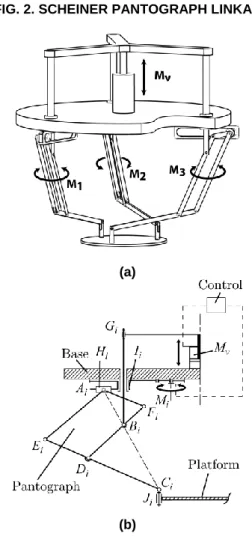
The typical limbs are single-open-chains which are kinematic chains serialized by only binary-joint-links. For the development of new architectures, the pantograph linkage is used as a limb. The pantograph is a mechanical system with two input points Ai and Bi and one output point Ci (Fig. 2). These input points linearly control the displacement of the output point Ci. Thus one linear actuator connected with input point Bi can control the vertical displacement of the output point Ci and the other linear actuator with horizontal axis can control its horizontal displacements. Note please that these motions are completely decoupled, i.e. they can be carried out independently.
Let us suppose that there is a concentrated mass in the point Ci. In this case, the load of the gravitational forces on the actuator of the horizontal displacements will be equal to zero
(the gravitational forces are always perpendicular to the displacements). With regard to the actuator for the vertical displacements, the load of the gravitational forces is not zero (the gravitational forces are parallel to the displacements). However, the input/output relationships for vertical and horizontal displacements are linear and they are determined by the magnification factor of the pantograph. These properties of the pantograph mechanism are used in the new class of manipulators called PAMINSA.
FIG. 2. SCHEINER PANTOGRAPH LINKAGE.
(a)
(b)
FIG. 3. PAMINSA WITH 4-DOF (a); KINEMATIC CHAIN OF EACH LIMB (b).
Now let us connect three Scheiner pantograph linkages with the base and the platform as it is shown in Fig. 3. In the obtained structure, one vertical actuator Mv controls the vertical displacement of point Bi of the pantograph linkages, and as a result, the vertical displacement of pairs Ci of the moving platform. The generation of motion in the horizontal plane is achieved by the actuators M1, M2 and M3 connected through
two passive pairs (Hi and Ii) with input joint Ai. The movement of each chain MiHiIi is planar as well as the displacement of input joint Ai. As a result, actuators Mi control the horizontal displacements of points Ci.
Thus, it is easy to see, that for the suggested architecture, the vertical translation of the platform along z axis is decoupled from its displacements in the horizontal plane (translations alongx and y axes and rotation about z axis).
Among the obvious advantages of the suggested manipulator architecture, we had noted followings points: (i) the decoupling of the control powers in two parts, makes
it possible to raise an important payload to a fixed altitude by powerful actuators and then to displace it on the horizontal plane by less powerful actuators;
(ii) a great accuracy in the horizontal positioning, because the payload can be locked in the horizontal plane by mechanical architecture of the manipulator (in other words, if the position of the vertical actuator is fixed, the altitude of the platform cannot change);
(iii) the cancellation of static loads on the rotating actuators which displace the platform in the horizontal plane; (iv) the simplification of the vertical control based on linear
input/output relationships.
It should be noted that the motion generation of the input point Ai can be carried out by several manners. All architectures shown in appendix have the same properties mentioned above. The different schematics for input motion generation can be easily distinguished by the projection of the structure on the horizontal plane (the pair M’i – or H’i – corresponds to the displacement of both pair Mi – or Hi – and pantograph linkage).
Basic structures of PAMINSA
Based on this approach, it is possible to obtain parallel manipulators from 3 to 6 DOF [13]. Among several structures, the manipulators for the production of Schoenflies motions (Fig. 3) are more appealing for industrial applications because they allow the positioning of a device at a given point and then its orientation around one given axis.
The next evolution of manipulators PAMINSA showed that it is also possible to create fully-decoupled structures based on the pantograph linkages.
It should be noted that fully-decoupling the three possible translations of a manipulator is an important challenge for many researchers [7-9]. Such manipulators are able to replace the existing serial Cartesian robot (XYZ).
Let us consider for the first time a fully-decoupled PAMINSA manipulator with translatory motions.
Fully-decoupled architecture with 3 translatory DOF
As for the basic version of the PAMINSA with 4-DOF is concerned (Fig. 3), one vertical actuator Mv (Fig. 4) controls the vertical displacement of point Bi of the pantograph linkages and, as a result, the vertical displacement of pairs Ci of the moving platform. The horizontal displacements of the manipulator along x and y axes are allowed by the translations of actuators M1 and M3. Let us now suppose legs 1 and 2 are
disconnected from leg 3. Input points A1 and A2 are linked to
actuator M1 through the two kinematic chains H1I1 and H2I2.
Thus, if actuators M1 and Mv are fixed, the permitted passive motion of the platform is a pure translation along an axis parallel to joints H1 and H2. Analogically, the passive
displacement of point J3 of the third leg is a pure translation
along an axis parallel to H3. As a result, the planar projection of
the manipulator is equivalent to the decoupled planar parallel manipulator presented at figure 4b. Thus, the three translations of the manipulator are fully decoupled.
(a) Kinematic chain
(b) Planar representation FIG. 4. FULLY-DECOUPLED PAMINSA
WITH 3-DOF.
The kinematics of such a manipulator is very simple. Let q1, q3 and qv respectively be the articular coordinates of actuators M1, M3 and Mv. The coordinates of the controlled point of the platform are x, y and z. Thus we have the following relationship: Jq X , k k k 0 0 0 1 0 0 0 1 J
where X = [x, y, z]T, q = [q1, q2, qv]T and k is the magnification factor of the pantograph linkages. Thus, the velocity equation is:
q J
X
So, J is the Jacobian matrix of the manipulator. Since J is a constant diagonal matrix with non zero elements, the manipulator does not have any singularities of Type 1, 2 and 3 [15]. However, please note that only cases of singularities appear with the degeneracy of the parallelograms AiEiDiFi.
Our observations showed that, in the typical fully-decoupled manipulators, the payload is supported by only one limb. In the case of the suggested structure, the distribution of the payload is more efficient because each limb carries only a fraction of the load. As a result, the manipulator based on these properties should have a better stiffness.
INPUT TORQUES MINIMIZATION
In this section, the minimization of input torques of PAMINSA manipulator with 4-DOF is discussed. The optimal results are obtained on the bases of static and dynamic models of the manipulator developed in [16].
Reduction of input torques in static mode of operation.
In [16], it was shown that the input torques due to the gravitational forces of the pantograph linkage can be cancelled by its optimal redistribution. Thus, by complete static balancing of legs, it should be possible to cancel the loads due to the movable masses of the limbs on the rotating actuators.
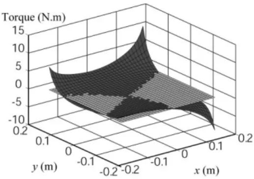
Fig. 5 shows the variations of the actuator torques before and after mass balancing. After complete static balancing the potential energy of the manipulator is constant for any configuration and zero actuator torques are required.
FIG. 5. VARIATIONS OF THE ACTUATOR TORQUES FOR
z = -0.6 m AND = 0° BEFORE (DARK GREY) AND AFTER (BRIGHT GREY) STATIC BALANCING OF LEGS. The presented example was calculated using the link parameters of the developed prototype [16]. The added masses are located at the axis Fi and their values are 2.8 kg (to observe the increase in masses after balancing, it should be noted that the mass of each pantograph linkage before balancing was 3.1 kg).
It is obvious that such a balancing is very useful for static applications of the manipulator. However, in the case of increase in acceleration of the movable masses, the complete static balancing becomes ineffective because the increase in inertia forces leads to the complementary loads. That is why an optimal balancing of limbs is considered below.
Reduction of input torques in dynamic mode of operation
In [16], we presented an analytic dynamic model of PAMINSA based on the Lagrange equations:
4 1 d d i ij i j j j A Q q L q L t where i are the Lagrange multipliers (i=1,…, 4), qj are the generalized coordinates (j=1,…,8), Qj are the input torques or forces.
Coefficients Aij are obtained by differentiating the closure-loop equations of the manipulator with respect to the generalized coordinates. Then the given system of equations is solved as follows: firstly the Lagrange multipliers must be obtained from the first four Lagrange equations (for qj = x, y, ,
z) and then the input torques/forces Qj can be determined from the last four Lagrange equations.
(a) Displacement along x-axis
(b) Displacement along y-axis
FIG. 6. THE PRESCRIBED TRAJECTORY FOR z = -0.7 m and = 0°.
(a) TORQUE OF THE ACTUATOR M1
(b) TORQUE OF THE ACTUATOR M2
(c) TORQUE OF THE ACTUATOR M3
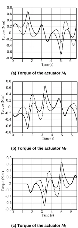
FIG. 7. ACTUATORS’ TORQUES FOR UNBALANCED (FULL LINE) AND STATICALY BALANCED MANIPULATORS
(DOTTED LINE).
For a comparative analysis of the unbalanced and statically balanced manipulators in dynamic mode of operation, a prescribed trajectory in horizontal plane is defined (Fig. 6) and, for the manipulator parameters given in [16], the input torques are determined (Fig. 7).
Thus, the obtained results showed that in the case of accelerated motions for input torques minimization, it is better to achieve a partial mass balancing.
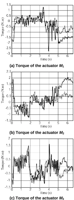
(a) Torque of the actuator M1
(b) Torque of the actuator M2
(c) Torque of the actuator M3
FIG. 8. ACTUATORS’ TORQUES FOR UNBALANCED (FULL LINE) AND PARTIALY BALANCED MANIPULATORS
(DOTTED LINE).
The minimization problem can be expressed as the following: ip ipr m dyn j
Q
,min
max
i.e. it is necessary to find such a distribution rip of moving masses mip which allows the minimization of the maximum values of the input torques.
The calculated values of added masses located at the axis Fi of each leg are 1.3 kg. The values of the input torques after complete static balancing and optimal balancing are presented in figure 8.
Thus, the analysis of obtained results showed that such an optimization allows the reduction of the maximal values of the input torques up to 45%.
PROTOTYPE AND EXPERIMENTAL TESTS
In the I.N.S.A. of Rennes, a prototype of PAMINSA for the production of Schoenflies motions was built (Fig. 9) [13]. The displacements on the horizontal plane of the developed prototype are obtained by Harmonic Drive motors connected with the legs by means of toothed-belt transmissions.
FIG. 9. PROTOTYPE OF THE PAMINSA WITH 4-DOF. As an actuator which controls the linear displacement of the vertical axes of the manipulator’s legs, the PARVEX motor system was chosen. Considering that the pantograph links are hollow aluminum tubes with a thickness of 1.5 mm, the pantograph linkage has been carried out with double rods in order to improve the stiffness of the manipulator.
Validation of the design concept
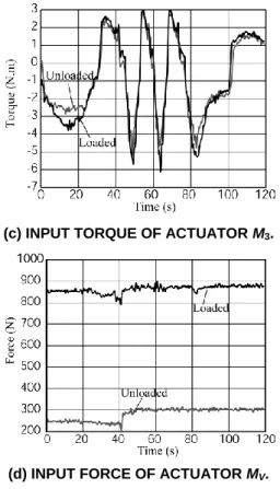
In order to validate the suggested design concept, we have measured the input torques/efforts of the actuators with the payload of 200 N (Fig. 9a) and without it (Fig. 9b) for the trajectory given in figure 10. The obtained results are presented in figure 11.
The numerical simulations were validated by experimental tests. The curves with and without payload for the 3 rotating actuators (Fig. 11a, b, c) are superposed. We can see that they
are similar, i.e. the loads on these actuators are cancelled. The small differences might result from friction in the joints, manufacturing errors, elasticity of the links and tracking errors.
Regarding vertical actuator (Fig. 11d), it supports the payload and the increase of the input force is significant.
FIG. 10. POSITION OF THE PLATFORM FOR
z = -0.6 m AND = 0 °.
(a) INPUT TORQUE OF ACTUATOR M1.
(b) INPUT TORQUE OF ACTUATOR M2.
(c) INPUT TORQUE OF ACTUATOR M3.
(d) INPUT FORCE OF ACTUATOR MV.
FIG. 11. INPUT TORQUES/EFFORT ON THE ACTUATORS WITH AND WITHOUT AN EMBEDDED LOAD OF 200 N.
Reduction of input torques in static mode of operation.
The static balancing of the manipulator is experimentally accomplished by adding counterweights of 2.8 kg at the axis Fi of the pantograph linkages (Fig. 12).
FIG. 12. COUNTERWEIGHTS ADDED ON PANTOGRAPH LINKAGES.
In order to prove the minimization of input torques before and after balancing, some arbitrary configurations of the manipulator were examined. The tested poses are given in table 1.
For these seven positions of the platform, the maximal absolute values of the input torques of the 3 rotating actuators before and after complete static balancing are measured (table 2). The reduction of the maximal input torques varies from 74% to 85%.
TABLE 1 THE POSES FOR THE EXPERIMENTAL VALIDATION OF THE STATIC BALANCING.
Pose x (m) y (m) z (m) (deg.) 1 0.124 0.096 -0.6 34.72 2 0.015 0.047 -0.615 -20.23 3 -0.149 0.009 -0.733 4.53 4 0.072 0.129 -0.497 9.23 5 -0.053 0.09 -0.540 33.92 6 -0.134 -0.075 -0.389 -3.5 7 -0.173 -0.042 -0.687 15.64 TABLE 2 THE ABSOLUTE VALUES OF THE MAXIMAL INPUT TORQUES BEFORE (CASE 1) AND AFTER (CASE 2) STATIC BALANCING Pose Case 1 (N.m) Case 2 (N.m) Reduction
1 1.78 0.46 74 % 2 1.81 0.26 86 % 3 1.38 0.34 76 % 4 3.31 0.47 86 % 5 3.23 0.59 82 % 6 1.93 0.35 82 % 7 2.4 0.55 77 %
Reduction of input torques in dynamic mode of operation.
For the trajectory given in Fig. 6, we measure the input torques of the three rotating actuators for cases (without any payload and with the payload for dynamic mode of operation).
Figure 13 shows the obtained results. The reduction of the maximal input torques with the added counterweight of 1.3 kg varies from 41% to 55%.
Thus, we can note that the obtained measures prove all numerical simulations presented above.
CONCLUSIONS
PAMINSA is a new family of parallel manipulators designed for high load carrying. In this paper, new results concerning these manipulators are presented. Particularly, a new architecture with 3 fully decoupled translatory motions is disclosed.
(a) Torque of the actuator M1
(b) Torque of the actuator M2
(c) Torque of the actuator M3
FIG. 13. ACTUATORS’ TORQUES WITHOUT (FULL LINE) AND WITH (DOTTED LINE) ADDED MASSES FOR DYNAMIC
OPTIMIZATION
The reduction of the input torques is also studied. It is shown that, for a dynamic mode of operation, the complete static balancing can not be effective in terms of input torques. In the case of accelerated motions, it is proposed to carry out an optimal redistribution of the movable masses and to achieve a partial mass balancing.
Then, a prototype of PAMINSA and experimental tests are presented. It is shown that the experimental tests prove the validity of the suggested design concept and the numerical simulations.
Finally, it should be noted that the proposed manipulators have been patented [17] and additional information is available upon request.
REFERENCES
[1] Bouzgarrou, B. C., Fauroux, J. C., Gogu, G., and Heerah, Y., 2004, “Rigidity Analysis of T3R1 Parallel Robot with Uncoupled Kinematics,” ISR-2004, Paris, France.
[2] Yu, A., Bonev, I. A., and Zsombor-Murray, P., 2006, “New XY-Theta Positioning Table with Partially Decoupled Parallel Kinematics,” IEEE International Symposium on Industrial Electronics (ISIE 2006), Montréal, Québec, July 9– 13.
[3] Bernier, D., Castelain, J.M., and Li, X., 2005, “A New Parallel Structure with 6 Degrees of Freedom,” Proceedings of the 9th World Congress on the Theory of Machines and Mechanisms, Milan, Italy, pp.8-12.
[4] Di Gregorio, R., 2001, “A New Decoupled Parallel Manipulator,” Proceedings of the 10th International Workshop on Robotics, Vienna, Austria, May 16-18.
[5] Lallemand, J.P., Goudali, A., and Zeghloul, S., 1997, “The 6-dof 2-DELTA Parallel Robot,” Robotica, 15, pp. 407-416. [6] Carricato, M., and Parenti-Castelli, V., 2004, “A novel fully decoupled 2-dof parallel wrist,” The International Journal of Robotics Research, 23(6), pp. 661–667.
[7] Carricato, M., and Parenti-Castelli, V., 2004, “On the topological and geometrical synthesis and classification of translational parallel mechanisms,” Proceedings of the 11th World Congress in Mechanism and Machine Science, Tianjin, China, pp. 1624–1628.
[8] Kong, X., and Gosselin, C. M., 2002, “A Class of 3-DOF Translational Parallel Manipulator with Linear Input - Output Equations,” Workshop on Fundamental Issues and Future Research for Parallel Mechanisms and Manipulators, Quebec City, Quebec, Canada, pp. 25-32.
[9] Gosselin, C. M., Kong, X., Foucault, S., and Bonev, I.A., 2004, “A Fully Decoupled 3-DOF Translational Parallel Mechanism,” PKM International Conference, Chemnitz, Germany, pp. 595- 610.
[10] Gogu, G., 2005, “Singularity-Free Fully-Isotropic Parallel Manipulators with Schönflies Motions,” Proceedings of the ICAR International Conference on Advanced Robotics, July 18-20, pp. 194-201.
[11] Arakelian, V., 1998, “Equilibrage des manipulateurs manuels,” Mechanism and Machine Theory, 33(4), pp. 437-442.
[12] Arakelian, V., 2004, “The history of the creation and development of hand-operated balanced manipulators,” Proceedings of the HMM2004, Kluwer Academic Publishers. [13] Arakelian, V., Briot, S., Guegan, S., and Le Flecher, J., 2005, “Design and Prototyping of New 4, 5 and 6 Degrees of Freedom Parallel Manipulators Based on the Copying Properties of the Pantograph Linkage,” Proceedings of the 36th International Symposium on Robotics (ISR), 29 November – 1st December, Tokyo, Japan.
[14] Briot, S., and Arakelian, V., 2007, Singularity analysis of PAMINSA manipulator,” 12th IFToMM World Congress, Besançon, France, June 18-21.
[15] Gosselin, C.M., and Angeles, J., 1990, “Singularity analysis of closed-loop kinematic chains,” IEEE Transactions on Robotics and Automatics, 6(3), pp.281-290.
[16] Arakelian, V., Briot, S., and Guégan, S., 2005, “Static and Dynamic Analysis of the PAMINSA,” Proceedings of
IDETC/CIE, ASME 2005, september 24-28, Long Beach, Californie, USA.
[17] Arakelian, V., Maurine, P., Briot, S., and Pion, E., 2006, “Robot Parallèle Comprenant des Moyens de Mise en Mouvement Décomposés en Deux Sous-Ensembles,” WO 2006/021629, January 27th.
APPENDIX
EXAMPLES OF MOTION GENERATION OF THE INPUT POINT AI OF PANTOGRAPH LINKAGES
Kinematic chain Planar representation 3D representation Type Schematics 3-RRR 3-RRR 3-RPR 3-RPR 3-RRP
3-PPR
3-PPR
3-PRR
3-PRR