PRE-STUDY OF THE HYDRAULIC WORKS
FOR THE SEINE-SCHELDT-EAST PROJECT
by
P. Rigo1, V. Herbillon2, L. Buldgen3, Y. Cordier4, D. Bousmar5, J.M. Hiver6
ABSTRACT
The Seine-Scheldt-East project in the Walloon Region (Belgium) requires the upgrade to Class Va of the waterways between the Scheldt and the Sambre Rivers. This project involves amongst other the building of 4 new locks at Obourg (Centre canal), Viesville, Gosselies and Marchienne-au-Pont (Charleroi-Brussels canal) and 2 new movable weirs at Kain and Hérinnes (Scheldt River). The Service Public de Wallonie (SPW), represented by the Hydraulic Research Laboratory, has therefore requested a pre-study to ULg-ANAST and Hydroconsult to define the general layout of the new locks and weirs, with a particular emphasis on standardisation. After collection of relevant data, appropriate technical solutions were selected through a multicriteria analysis, before being adapted to each particular site (feasibility study).
1. INTRODUCTION
The Seine-Scheldt link, a priority project of European Union’ Trans-European Network of Transport program (TEN-T), will connect the Seine and Scheldt river basins, and, to a broader extent, the entire Rhine-Scheldt delta and the Rhine basin. The main axis Compiègne-Ghent is designed for push-tows up to 4400 tons (Class ECMT Vb). A lateral branch, located in Wallonia and called Seine-Scheldt-East, will connect the main axis to River Meuse, for class Va vessels (Figure 1). This branch uses existing canals between Scheldt and Sambre Rivers that will be upgraded with new locks and enlarged sections: Pommeroeul-Condé, Nimy-Blaton-Péronnes, Centre and Charleroi-Bruxelles canals.
Figure 1: Seine-Scheldt Network, general map.
1 Professor, University of Liege, ANAST, Belgium, ph.rigo@ulg.ac.be 2 University of Liege, ANAST, Belgium, vincent.herbillon@ulg.ac.be 3 University of Liege, ANAST, Belgium
4 Director, HydroConsult, Brussels, YCordier.hc@skynet.be
5 Direction des Recherches Hydrauliques, SPW, Belgium, didier.bousmar@spw.wallonie.be 6
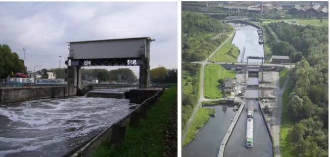
This project involves amongst other the building of 4 new locks at Obourg (Centre canal), Viesville, Gosselies and Marchienne-au-Pont (Charleroi-Brussels canal) and 2 new movable weirs at Kain and Hérinnes (Scheldt River) (Figure 2). To facilitate the study and the planning of these works, the Service Public de Wallonie (SPW), represented by the Hydraulic Research Laboratory has requested a pre-study to University of Liege (ULG-ANAST) and Hydroconsult.
Figure 2: View of existing sites: (a) Kain’s weir, Scheldt River; and (b) Marchienne-au-Pont’ lock, Charleroi-Bruxelles canal.
The main purpose of this pre-study was to define, in close cooperation with the engineering services of SPW, the general layout of the four new locks and two movable weirs, with a particular emphasis on standardisation. It was organised in three mains phases:
1. Collection of relevant data from the field, such as geotechnical, hydrology, topography, etc. and definition of specification guidelines for the project, including design objectives and technical aspects;
2. Identification of all feasible technical solutions and selection of the most appropriate one through a multicriteria analysis;
3. Adaptation of the generic layout to each particular site, drawings and cost estimations. These three phases are briefly described here after.
2. DATA COLLECTION, SPECIFICATION GUIDELINES
In parallel to the collection of data, we established technical guides for the weirs and the locks. The aim of those guides (or design requirement guidelines) was to define the expected levels of performance of the various technical components.
For the locks, the performance objectives are linked to:
- Traffic fluidity (cycle duration, limitation of navigation interruptions for maintenance or climate reason)
- Safety (signalization, protection against collision with a ship, transport of dangerous material, protection against vandalism, safety for the workers)
- Capacity of the locks (Va)
- Lifecycle of the locks (100 years for the concrete parts, with an appropriate planning of maintenance)
- Water alimentation of the canals (lock consumption) - Environmental aspects
For the weirs, the performance objectives are linked to:
- Reliability during extreme weather conditions (flood, low flows, ice, etc.) - Reduced duration of the works to reduce interaction with flood season
- Safety (signalization, impact of a ship on a pier or an abutment, protection against vandalism, etc.)
- Lifecycle of the weirs
- Discharge capability of the weirs
- Accuracy of the water level control for the navigation - Interaction with the navigation
- Fish ladders - Hydroelectricity - …
3. MULTICRITERIA
ANALYSIS
3.1 MethodologyThe first step of the multicriteria analysis was the selection of different technical design alternatives (including innovative choices such as inflatable weirs or sliding valves for the locks), selection of the construction method, gate type, filling and emptying systems, etc. but also on the possible locations. For instance, the construction of the new weirs, the following locations were considered: upwards or downwards of the existing weir or in a separate channel. The most relevant alternatives were selected as reference for different layouts.
In a second step, in collaboration with SPW, main criteria were defined and divided in 3 subcategories: - cost of installation (concrete, hydraulic cylinders, gates, valves, …)
- technical aspects (reliability, maintenance, exploitation, navigation) - non technical aspects (environment, social impact, landscape).
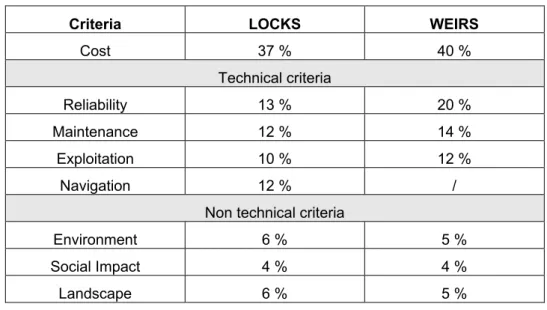
Each criterion received a weighting factor assigned by the SPW delegates. The respective weighting factors are listed in Table 1 for locks and weirs. For example, the higher weight given at the reliability criteria of weirs (compared to locks) highlights the perception of the consequences of a failure during flood period.
The different design alternatives were then compared through those criteria.
Criteria LOCKS WEIRS
Cost 37 % 40 % Technical criteria Reliability 13 % 20 % Maintenance 12 % 14 % Exploitation 10 % 12 % Navigation 12 % /
Non technical criteria
Environment 6 % 5 %
Social Impact 4 % 4 %
Landscape 6 % 5 %
Additionally, a sensitivity analysis was performed by varying the weighting factors of some criteria to assess how the conclusions could change (increase of the weight of either the cost, either the technical criteria, either the non-technical criteria). As a result of this sensitivity analysis it was observed that the conclusions were affected by the relative weight of the cost and the technical criteria. This issue was discussed with the SPW and showed clearly that the design must be changed if the cost becomes the key criteria, instead of the technical performance. At the end, this method helped to propose the best choice considering the requirements and the objectives of the SPW.
In Tables 2 and 3 are listed the different main design alternatives considered (Base 1 to Base n), as well as their options (each alternative can be associated with some options).
3.2 Design of the weirs
The reference weir design alternative is the Base 1 (see Table 2). It is a weir with 2 spans equipped of flap gate and built in a new channel (in the dry). Each flap is controlled on both sides by hydraulic cylinders (each cylinder must be able to control alone the flap).
The six options are linked to the reference solution (Base 1). They are presented to assess clearly how much they bring as (dis)advantages (quantitatively). If suitable, the best options can be also used for the other alternatives (Base 2 – Base 5).
For the weirs, options 5 and 6 were quickly discarded because there are too many disadvantages to build the new weirs in the current channel (problem of the navigation, etc.). In addition, options 1 and 2 were not taken into account because of their higher cost.
The main advantage of the flap gate is the price. Even if it is not the best solution from a technical point of view (hinges under water, accumulation of sediments, etc.) it is a relevant solution as already used without any problem on the Haine river in Belgium, and it is the best compromise between technical elements, non technical elements and the cost.
The only interesting option, giving a bonus to the reference solution, was to use a simplified energy dissipation basin. Description Cotation (max=5) Ranking Base1 (= reference) 2 flap gates 4.439 1
Base2 2 Obermeyer gates 3.943 5
Base3 2 radial gates (with upper flap gates) 4.194 2
Base4 2 vertical lifting gates (with upper flap gates) 4.054 4
Base5 2 radial gates (with overflow and under flow) 4.136 3
Options (in addition to Base 1)
Option1 3 spans instead of 2 4.283
Option 2 3 spans with 1 for hydroelectricity 4.108
Option 3 Use of prefabricated elements 4.194
Option 4 Simplified dissipation basin (see Figure 5) 4.463
Option 5 Construction in the current channel (upstream) 4.231
Option 6 Construction in the current channel (downstream) 4.231
3.3 Design of the locks (Table 3):
The reference lock design alternative is the Base 2 (see Table 3). It is a lock built beside the existing one. It is 112.5 m long (149 m in Obourg) and 12.5 m wide. The downstream heads from the old lock and the new lock are in a line. We will use a U shape for the floor and the side walls of the lock. Filling and emptying (F&E) is done through the heads - short culvers (upstream & downstream heads). The pumping is made with the existing station (which must be modernised). The valves used in the culverts are butterfly valves.
There are seven options, which refer to the reference lock design (Base 2). They are useful to assess clearly how much they bring as (dis)advantages (quantitatively). If suitable, the most suitable options can be also used for the other alternatives (Base 1, Base 3 or Base 4).
For the locks, it appeared quickly that the reference solution would be a F&E system through the head (short culverts), for both upstream and downstream heads.
As options 6 and 7 may induce serious problems for the landscape integration or for the navigation they were not considered as “feasible” solutions.
Two options obtained a good result: the rolling suspended-gates and a design with side walls independent of the lock floor.
Description Cotation
(max=5) Ranking
Base1 Upstream: radial gate, integrating F&E
Downstream: mitre gate, F&E through the heads - short culvers
3.651 4
Base2 (= reference)
F&E through the heads - short culvers (upstream & downstream heads), with butterfly valves,
U shape lock, Miter Gates
3.889 1
Base3 F&E with side wall aqueducts and side ports 3.856 2
Base4 Saving basins, with sliding valves, flap gate,
+ pumping station 3.656 3
Options (in addition to Base 2)
Option1 Independent side walls and independent floor 3.898 Option 2 Prefabricated construction < 3.5
Option 3 Upstream: flap gate Downstream: mitre gate 3.794
Option 4 Suspended rolling gate (downstream & upstream) 3.897 Option5 Lifting valves for F&E (rolling type) 3.823
Option6 Twinning of the chamber locks (the existing one and
the new one) < 3.5
Option7 Reduction of the number of reaches
(i.e. 2 locks instead of 3, by changing the elevation of the reaches)
< 3.5
For the SPW experts, the rolling suspended-gates (Figure 3) appeared to be the best choice even if slightly more expensive (initial investment). These gates were qualified by the SPW as the “most reliable” from a technical and operational point of view (maintenance, watertightness, etc.) in comparison to the standard mitre gates.
Figure 3: Rolling Suspended Gate
4. SUGGESTED
LAYOUTS
4.1 Weirs
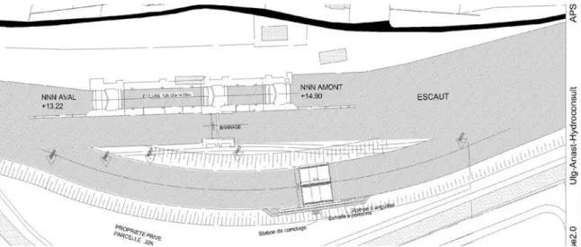
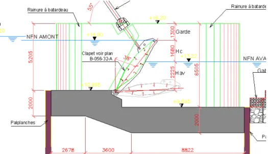
For the movable weirs (river navigation control), the best solution (as defined by the multicriteria assessment) is a two 12 m-spans movable weir with flap gates; weir built in a new channel (derivation channel, see Figure 4), with an optimized simplified downstream energy dissipation basin (Figure 5). Because of the presence of gate hinges in the water, the study pointed out the need of a regular inspection and maintenance for those mechanical parts.
As the SPW wanted a standardized solution, the same solution was proposed for Kain and Hérinnes, so that it will induce cost savings for maintenance and exploitation. As the water head is similar for both weirs (1.60 m vs 1.90 m), an identical standardized flap gate was proposed for both locations. The weirs will be built in a new channel, so that the water level for navigation and flood control won’t be perturbed during the work. For the fish pass, we have chosen two different solutions, because the available place is different for Kain and Hérinnes. In Hérinnes, a small artificial river around the weir is suggested. In Kain, a fish ladder with basins, placed next to an abutment, seems more appropriate. A hydro power plant could be installed on both sites to generate green energy.
Figure 5: Flap gate and simplified energy dissipation basin.
For all solutions, quantities were assessed to evaluate the cost of the project. The provisional cost is estimated at about 2 500 000 Euros (excl. VAT and hydropower installations). Drawings of the weirs were presented at their future positions (see Figures 4 and 5). Longitudinal and cross section were also given to SPW.
4.2 Locks
For the locks, the best solution is monolith U chamber lock, with suspended transversally rolling gate and short culvert filling-emptying system, both upstream and downstream (see Figure 7).
The designers considered also as criteria for the implantation of the locks and the approach walls the ship manoeuvrability and the approach areas of the new and the old locks and the induced modifications for the canal (widening of the waterway, size of the guiding walls, position of the waiting berths, etc., see Figure 6).
For all solutions, quantities were assessed to evaluate the cost of the project. For each lock, the provisional cost is estimated at about 30 000 000 Euros (excl. VAT).
Drawings of the locks were presented at their future positions (see Figures 6 and 7). Longitudinal and cross section were also given to SPW.
Figure 7: Principles of the F&E system and the gate type of the new lock. Horizontal sections in the upstream and below downstream lock heads
5. CONCLUSIONS
This feasibility study highlights the importance of multicriteria analysis as decision tool to avoid wrong choice at the early design stage. Indeed, such erroneous choice could usually not be changed latter in the next steps of the project without significant delay and additional cost. Such approach helps decision-makers to identify objectively a set of optimal solutions. A key issue is the definition of the criteria but even more important is the assessment of the weighting factors of these criteria. The criteria and their associated weighting factors have to be discussed seriously to obtain a pertinent and reliable result. It is also worthy to enlarge the consulted panel of experts, in order to reduce the subjectivity of these weighting factors.
The present pre-study was helpful to the SPW to make an objective choice of the most appropriate layout of the future works. It is now possible to invite tenders for the details civil and mechanical engineering studies (probably in the course of 2010). The formal justification of the selected solutions, together with the evaluation of relevant variants, will also be very valuable for public communication during the environmental impact assessment studies required to obtain building licence.
6. ACKNOWLEDGEMENT
The studies reported in this paper are co-financed by the European Union’ Trans-European Network of Transport program (TEN-T), 2007-EU-300010-P, decision C(2008) 8141 of December 15, 2008. The sole responsibility of this publication lies with the authors. The European Union is not responsible for any use that may be made of the information contained therein.
REFERENCES
Hydroconsult, ULG-ANAST (2009). Preliminary design of the locks and weirs of the Seine- Escaut Est