- 1 -
LH*
RS
P2P
: A Scalable Distributed Data Structure for
P2P Environment
Witold Litwin
Université Paris-Dauphine
Place Marechal de Lattre de
Tassigny 750016 France
(0033)1 4405-4880
[email protected]
Hanafi Yakouben
Université Paris-Dauphine
Place Marechal de Lattre de
Tassigny 750016 France
(0033)1 4405-4047
[email protected]
Thomas Shwarz
Santa Clara University
500 El Camino Real
Santa Clara, California 95053-0566
(408) 551-6064
[email protected]
ABSTRACT
LH*RSP2P is a Scalable Distributed Data Structure (SDDS) designed for P2P applications. It stores and processes data on SDDS peer nodes. Each node is both an SDDS client and, actually or potentially, an SDDS server with application or parity data. The scheme builds on LH*RS scheme principles. The basic difference is that LH*RSP2P key based queries require at most one forwarding message, instead of two for LH*RS. This makes LH*RSP2P the fastest P2P and SDDS addressing scheme currently known. In addition, the LH*RSP2P scan has the upper limit of two rounds. LH*RSP2P parity management reuses the LH*RS Reed Salomon erasure correction scheme to deal efficiently with churn. The file supports unavailability or withdrawal of up to any k ≥ 1 peers, where k is a parameter that can scale dynamically. We discuss the LH*RSP2P design, implementation issues and variants, as well as the related work.
Keywords
Scalable Distributed Data Structure (SDDS), P2P system, Linear Hashing algorithm (LH)
1. INTRODUCTION
The concept of a Scalable Distributed Data Structure (SDDS) appeared in 1993 [5]. It was intended for multicomputers and more specifically for networks of interconnected workstations. Some SDDS nodes are clients, interfacing to applications. Others are servers storing data in buckets and addressed only by the clients. The data are either application data or the parity data for a high-availability SDDS such as LH*RS [9]. Overloaded servers split, migrating data to new servers to make the file scalable. The first SDDS was the now popular LH* schema that exists in several variants and implementations [6, 7, 9]. A key search in LH* needs at most two forwarding messages (hops) to find the correct server, regardless of the size of the file. This property makes the LH* scheme and its subsequent variants a very efficient tool for applications requiring fast growing and large files such as distributed databases in general, warehousing, document
repositories, e.g., for eGov, stream data repositories…
In the early 2000s, Peer-to-Peer (P2P) systems appeared and became a popular topic. In a P2P system, each participant node functions as both a client and a data server. The earliest P2P systems implemented file sharing and used flooding of all nodes for each search. To avoid the resulting message storm, structured P2P systems use additional data structures to make searches more efficient, [11, 1]. Structured P2P are in fact specific SDDSs under a new brand name. Dynamic Hash Table (DHT) based structures are the most popular [3, 10]. The typical number of hops is O (log N) where N is the number of peers storing the file. Some peers may be super-peers performing additional coordination functions.
The coordinator in LH* is a super-peer in this terminology. However, a client is not a peer since it does not store any part of the SDDS file. It can be off-line or on-line without having an impact on the remaining system. In contrast, an SDDS server is designed to be available at all time. An LH* peer is a node that contains (at least potentially) both a client and a server. In consequence, LH* peers strive to be always online. In this scenario, it becomes reasonable to assume that a server forwards from time to time some meta-data to selected clients. It may always send such data to its local client, but also to a few remote ones. To improve the already excellent LH* routing (typically, but not always one hop), pushing information on bucket splits and merges appears especially useful. Closer analysis that will appear in what follows shows the possibility to decrease the worst case forwarding to a single message only.
A typical P2P system suffers not only from temporary unavailability of some of its constituent nodes, but also from
churn, the continuous leaving and entering of machines into the
system. For example, a P2P system (a.k.a. a desktop grid) such as Farsite [2], currently in the process of being commercialized, uses the often underused, considerable desktop computing resources of a large organization to build a distributed, scalable file server. Even though participant nodes are under the control of the organization, the natural cycle of replacing old system by new ones will appear to the P2P storage system as random churn. However, a file server or a database needs the availability of all its data, regardless of the fate of some participant nodes. Some redundancy of stored data becomes then necessary. LH*RS responds to the database high-availability needs with a specific parity calculus. It is done over so-called groups of size m = 2i of
its application data buckets. The value of m is arbitrary; thought in practice should be like 8 – 32. The scheme tolerates the
Permission to make digital or hard copies of all or part of this work for personal or classroom use is granted without fee provided that copies are not made or distributed for profit or commercial advantage and that copies bear this notice and the full citation on the first page. To copy otherwise, or republish, to post on servers or to redistribute to lists, requires prior specific permission and/or a fee.
8th annual international conference on New Technologies of Distributed Systems. June 23-27, 2008. Lyon, France
- 2 - unavailability of up to any k ≥ 1 of servers per group. The value of
k may scale dynamically, providing the k-availability to the file.
The calculus uses a new variant of Reed Salomon erasure correcting coding. The storage overhead is small, in the orders of
k / m. These properties seem attractive to deal with reasonable
amounts of churn as well.
All these observations are the rationale for the LH*RSP2P design. We now present it more in depth. Section 2 recalls the basic addressing algorithms and presents our peer architecture. Section 3 presents the LH*RSP2P file evolution. Section 4 discusses the file manipulation. In Section 5 we discuss churn management. Section 6 presents the implementation. Finally we discuss variants of LH*RSP2P in Section 7 and conclude in Section 8.
2. LH*
RS P2PFILE STRUCTURE
2.1 Architecture Overview
The LH*RS P2P file structure is based on the LH*RS file. We assume that the reader is familiar with the latter [9]. The application manipulates an LH*RSP2P file as LH*RS file. It uses thus the key-based record search, insert, update or delete query, or a scan
query performing a non-key operation on all records in the file. These operations are performed similarly in LH*RS P2P and LH*RS. In an LH*RS file however, the nodes that process queries are either the clients through which the applications access the file or the servers storing the (application) data or parity buckets. In contrast, LH*RSP2P uses peer nodes, see Figure 1. A peer provides both functions. It has the client component (the client in what follows) and the data or parity server components.
Figure 1. LHRSP2P Architecture Overview
The latter components store, or are willing to, a data bucket or a parity bucket, as the service to the community for the file use. The parity data provide the k-availability to the LH*RSP2P file. Finally, one peer acts as the coordinator through its coordinator
component. This peer behaves like the LH*RS file coordinator
with additional capabilities we will show. The coordinator may eventually be replicated.
A peer with a data bucket is a (data) server peer. A peer with only a client component is a candidate peer. It serves as a hot spare, waiting for a bucket. This happens when there is no pending storage need for a new peer. A peer with a parity bucket is a
parity server peer.
As usual for an LH* file, a new data bucket is created from the split of an existing one. This is done by the server component of a peer. The coordinator assigns the new bucket to a candidate or multicasts a request for the storage, which is picked up by the fastest candidate. The splitting server component notifies its client component about each split. We will show soon how. It may send the information also to some candidate peers. We say that it acts as the tutor of its pupils. A pupil gets a tutor from the coordinator when it joins the file. It remains tutored as long as it does not get its data bucket. It then informs the tutor that ceases the notifications.
The parity management under LH*RS P2P scheme is basically the same as for LH*RS. There are additional capabilities we will discuss later.
2.2 Record Addressing
2.2.1 Global Rule
The addressing scheme of LH*RSP2P is that of LH* with differences we will now explain. As usual, a record of an LH*RS P2P file is identified by its primary key. The key C determines the record location (the bucket number a = 0,1,2..) according to the linear hashing (LH) algorithm [4]:
Algorithm (1) : LH*RSP2P Global Addressing Rule a ← hi (C) ;
If a < n then a ← hi+1 (C).
We recall that (i,n) are the file state. Here, i =0, 1… is the file
level. It determines the linear hash (LH) function hi applied. Basic
LH-functions are hi(C)= C mod 2i. Likewise, n = 0,1… is the split
pointer, indicating the next bucket to split.
2.2.2 Key-based Addressing
As is the case for
LH*
RS,
only the coordinator peer in theLH*
RSP2P file always knows the file state. Any other peer uses its local image (i',n') of the file state for addressing. The image may be outdated showing fewer buckets than actually in a growing file. (Since heavily shrinking files are infrequent in practice, bucket merges are rare or even not implemented.) The peer uses the image to find the location of a record given the key for a based query, or to scan all the records. We now review the key-based addressing. The next section deals with scans.The primary location of a record identified by its key C is the bucket with the address a given by (1). However, the peer applies Algorithm (1), to its client image only. It sends its key-based query Q, accordingly to some bucket a'. Q may search for a record, may insert it, update or delete. It always includes C. For the reasons we explain soon, it also includes its image (i',n').
An outdated image could result in a' < a. The peer then sent Q to an incorrect bucket. In every case, Q reaches the server component at the receiving peer a'. That one server component starts with the following algorithm. It first verifies whether its Pupil Tutor Client SERVER Parity Client Coordinator Network Peers Client SERVER Data Client SERVER Data
- 3 - own address is the correct one by checking its guessed bucket level j' in the received client image against its actual level j (the level of LH function last used to split or create the bucket). It calculates j' as i' for a' ≥ n' and as i' + 1 otherwise.
If needed, the server forwards Q. We will demonstrate later that Q always reaches the correct bucket a in this step. This is not true for LH* in general and LH*RS in particular, which may need an additional hop. Finally, the failure of j' test for forwarding, implies (as we will show below) that the image was outdated because of a communication failure with the tutor or churn or some other error. The addressee returns then the error information.
Algorithm (2) : LH*RSP2P Server Key-based Addressing If a' ≥ n' then j' = i' else j' = i' + 1;
If j = j' then process Q ; exit; Else if j' – j = 1 then a ← hj (C);
if a > a' then forward Q to bucket a ; exit;
Else send the "erroneous image" message to the sender;
If forwarding occurs, the new address a has to be the correct one. Hence the addressee does not perform the checking (2). (This is not the case for forwarding in LH*RS.) As usual for an SDDS, it only sends the Image Management Message (IAM). The IAM informs the sender that the initial address was incorrect. It includes the level j of the correct bucket a. In LH*RSP2P, it has to be also j of bucket a'. The sender adjusts then its image reusing the LH* Image Adjustment algorithm:
Algorithm (3) : LH*RSP2P Client Image Adjustment i’ = j ; n' = a' + 1 ; If n’ = 2i’ then i’= i' + 1; n’=0;
As usual for LH*, the adjusted image is more accurate with respect to the files state. It takes to the account at least one more split that happened since the image creation or its last adjustment. In particular, the addressing error that has triggered the IAM cannot happen again.
Server peer a has also physical (IP) addresses of buckets that the sender does not know about. These buckets are those beyond the last one in the received image (i’,n’) until a, namely n' + 2i', …, a.
Server peer a attaches the IP addresses to the IAM.
2.2.3 Scan
When a peer performs a scan S, it uses unicast to S to each bucket
a in its image, namely to buckets 0,1,.., n' +2i' – 1. Every message
contains j’. Every bucket that receives S verifies whether S needs to be forwarded because of a bucket it knows about, but the originating peer did not. It executes the following algorithm: Algorithm (4) : LH*RSP2P Server Scan Processing
If j = j' + 1 then a' = a + 2j-1 ; forward S to peer a' ; exit;
If j = j' then process S; exit;
Else send the "erroneous image" message to the sender;
The client peer may finally wish to execute the termination
protocol, to ensure that all the addresses have received S. This
protocol is the same as for LH*RS.
3. FILE EVOLUTION
3.1 Appending a Peer
A peer wishing to join the file contacts the coordinator. The coordinator adds the peer to its peer location tables and checks
whether there is a pending request for the bucket space. This is typically not the case. If the peer wishes to be a file client, it implicitly commits to be a data bucket. The coordinator declares the peer a candidate and chooses its tutor. The candidate becomes a pupil. To find the tutor, the coordinator uses the IP address of the candidate as if it was a key. Using Algorithm (1), it hashes the value and uses the result as the tutor's address. The coordinator sends the message to the tutor that in turn contacts the candidate. In particular, it sends its image, accompanied with the physical locations of the peers in the image. We recall from LH* principles that these are at least the locations of buckets 0… a + 2j -1 for a
bucket a. The pupil stores the addresses, initializes its image, starts working as a client and acts as a spare, waiting for a bucket need.
A split may necessitate finding a new parity bucket. The coordinator finds the peer willing to host it. This can be a candidate peer or a server peer. The candidate peer getting the parity bucket only will remain pupil until it gets a data bucket. Alternatively, as we have mentioned, there may be (philanthropic) peers willing to host parity buckets only, without being clients. A candidate upon becoming a (data) server informs the tutor that it is no longer its pupil. The tutor ceases monitoring it.
3.2 Splitting a Peer
When a peer splits its data bucket a, it updates its local image, using the j value before the split. If it has pupils, it sends them the information about the split, including j. The client at the peer and the pupils adjust the images using Algorithm (3). The image adjusted by Algorithm (3) reflects however the file state exactly this time.
With the request to split, the coordinator informs peer a not only of the physical addresses of the new bucket, but also those of the buckets that have been created since the last split of the peer. The latter are buckets a + 2j-1… a + 2j – 1, where the j value is the one
before the split. The peer is not aware of their existence if it did not get any IAM. The peer that is a tutor forwards the addresses to all its pupils. If the peer or a pupil got an IAM since the last split of the peer, it may already have some of these addresses, possibly even all. It may happen that there are two different addresses for the same bucket. This means that the bucket became unavailable and was recovered since the peer got its address. The peer uses the address sent by the coordinator.
The peer with the new data bucket initializes its image to the same values as in the after-image at the splitting peer. The splitting peer informs the new server of all the physical addresses of the predecessors of the new bucket. The images may remain unchanged until the next split of the tutor or until the first split of the newly created bucket. Alternatively, each image may get further adjusted by IAMs in the meantime.
When the splitting peer is a tutor, its pupil might receive the peer of the newly split-off bucket as a new tutor. This happens for the pupil with the address hashed to the new bucket after the split. If this happens, then the new tutor informs all its (new) pupils of the change of assignment. The scheme flexibly and uniformly spreads the tutoring load as more servers become available. The file can handle efficiently an increase in the number of pupils. As the file grows, we can expect this increase to occur.
The peer getting the parity bucket during a split behaves like the LH*RS parity server.
- 4 -
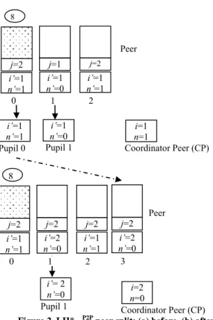
Figure 2. LH*RSP2P peer split: (a) before, (b) after
Example: Assume the file with data buckets distributed over three
peers, as in Figure 2(a). We neglect parity buckets. Peer addresses are 0, 1, 2 and the file state is i =1 and n = 1. The images at the peers are these created with their buckets, for peers 1,2 or adjusted during the last split of bucket 0. The image of peer 1 is outdated. Peer 0 and peer 1 are tutors, each with one pupil, numbered here upon the tutors. Peer 0 reached its storage capacity. Peer 1 inserts the record 8, i.e., with key C = 8. With its client image, it calculates 8 mod 21 = 0 and sends record 8 to address 0. Peer 0 executes Algorithm (2) and inserts the record. This creates an overflow and the peer contacts the coordinator. Given n = 1, the coordinator requests peer 1 to split. The split creates data bucket 3. Once the split completes, peer 1 adjusts its image to (2, 0). The coordinator does the same.
Assume that pupil 0 gets bucket 3. It becomes (server) peer 3. It initializes its client image accordingly to (2,0). It informs about its new status the tutor which takes note that this peer is no more its pupil. that it is no more after this the coordinator update it image (i, n). The final structure is shown in Figure 2(b).
4. ACCESS PERFORMANCE
We now prove the following basic properties of an LH*RSP2P file. They determine the access performance of the scheme, under the assumption that all the manipulated data buckets are available.
Property 1. The maximal number of forwarding messages for
key-based addressing is one.
Property 2. The maximal number of rounds for the scan search is
two.
Property 3. The worst case access performance of LH*RSP2P as
defined by Property 1 is the fastest possible for any SDDS or a practical structured P2P addressing scheme.
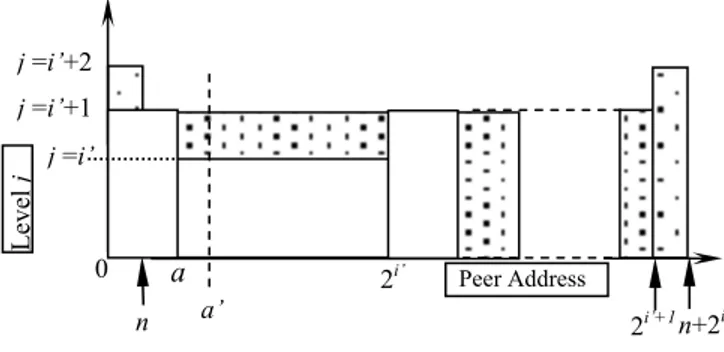
Figure 3. Addressing the region with no forward Proof of Property 1
Assume that peer a has the client image (i’, n’). Assume further that peer a did not receive any IAM since its last split using hi +1.
Hence, we have i’ = j-1, n’=a + 1. At the time of the split, this image was the file state (i, n). Any key-based addressing issued by peer a before next file split, i.e., of bucket a + 1, had no forwarding as show in Figure 3. Let us suppose now that the file grew further. The first possible case is depicted in Figure 4. Some buckets with addresses beyond a have split, but the file level i did not change, i..e. the split pointer n did not come back to n = 0. We thus have n > n’ and i’ = i. The figure shows the corresponding addressing regions. Suppose now that peer a addresses key C using Algorithm (2). Let a’ be the address receiving C from a. If
a’ is anywhere beyond [n’, n], then the bucket level j must be the
same as when peer a created its image. There cannot be any forwarding of C. Otherwise, a’ is the address of a bucket that split in the meantime. The split could move C to new bucket beyond 2i’- 1. One forwarding is thus possible and would be generated by
Algorithm (2). But this bucket could not split since the last split of bucket a that has created its current image. No other forwarding can occur and none is generated by the above presented addressing scheme.
Figure 4. Addressing the region with possibility of forward
The second case of addressing regions is illustrated by Figure 5. Here, the split pointer n came back to 0 and some splits occurred using hi’ +1. However, peer a did not yet split again, i.e., n ≤ a.
Peer a searches again for c and sends the search to peer a’. There are three situations:
a. We have n ≤ a’≤ a. A bucket in this interval did not split yet
using hi’ +1. Hence the bucket level j(a’) is as it was when the
image at peer a was created. There cannot be any forwarding, since j(a’)= i’ + 1 while n’ = a.
2i’ a’ n+2 i’ a 0 j =i’ j =i’+1
n a+2i’ Peer Address
Leve l j
n+2
i ’ 2i’ a n’0
j =i’ j =i’+1 n a’a+2
i ’ Peer Address Leve l j Pupil 0 Peer Coordinator Peer (CP) 0 j=2 i’=1 n’=1 j=1 i’=1 n’=0 j=2 i’=1 n’=1 2 i’=1 n’=0 i’=1 n’=1 Pupil 1 i=1 n=1 1 8 Peer Coordinator Peer (CP) 0 j=2 i’=1 n’=1 j=2 i’=2 n’=0 j=2 i’=1 n’=1 2 i’= 2 n’=0 Pupil 1 i=2 n=0 1 8 j=2 i’=2 n’=0 3- 5 -
Figure 5. Addressing regions in 2nd case.
b. We have a < a’ < 2i’ - 1. We are in case 1 above and there can
be one forwarding message. This is the situation shown at the figure.
c. We have a’<n. Bucket a’ split using hi’ +1 hence we may have
a forwarding of c towards bucket a’ + 2i’ this split has created
(one buckets at the right side ofthe Figure
5
. That bucket could not split yet again. Bucket a would need to split first sincea < 2i’. Hence, there cannot be 2nd forwarding of c.
These are the only possible cases for LH*RSP2P. Hence, there cannot be more than one forwarding during any key-based addressing. If peer a got any IAM in the meantime, then its image could only become more accurate with respect to the actual file state (see Property 4). That is n’ moves closer to n or ‘i’ becomes new i = i’ + 1 for Figure 5. No additional forwarding is possible, only the single forwarding becomes less likely.
Proof of Property 2
Assume that peer a now issues a scan search. It sends it to every peer a’ it has in its image. The file situation can be as at Figure 4 or Figure 5 above. In each case, peer a’ could split once. It recognizes this case through Algorithm (4) and forwards then the scan to its descendant. These messages constitute the second round. No descendant could split in turn. They have to be beyond bucket a itself which would need to split first. Hence, two rounds is the worst case for the LH*RSP2P scan.
Proof of Property 3
The only better bound is zero messages for any key addressing. The peer a that issues a key-based query can be any peer in the file. To reach zero forwards for any peer a would require to propagate synchronously the information on a split to every peer in the file. This would violate the goal of scalability, basic to any SDDS. The same restriction stands for structured P2P systems. Hence no SDDS, or practical structured P2P scheme can improve the worst case addressing performance than LH*RSP2P.
5. CHURN MANAGEMENT
LH*RSP2P copes with the churn through the LH*RS management of unavailable data and parity buckets. In more detail, it recovers up to k data or parity buckets found unavailable for any reason, in a single bucket group. Globally, if K is the file availability level,
K = 1, 2… then k = K or K = k +1. In addition, LH*RSP2P allows a
server or parity peer to quit with notice. The peer notifies the coordinator and stops dealing with incoming record manipulation requests. The data or parity bucket at the peer is transferred elsewhere. Any bucket in the bucket (reliability) group gets the new address. The quitting peer is finally notified of the success of
the operation. The whole operation should be faster than recovery, but the quitting peer now has to wait.
A pupil may always leave without notice. When its tutor, or the coordinator, does not receive a reply to a message, it simply drops it from its data structures. A special case arises if a network failure or similar happenstance disconnected the pupil from its tutor, but the pupil did not discover this disconnection. It will therefore no longer receive any updates. Without the benefits of these updates, a query by this pupil is essentially an LH* query and might therefore take two forwarding messages.
A similar situation may happen to a server peer that – not aware of being unavailable or having left – comes back and issues a query. Our solution for this situation does not fall back on LH* addressing with potentially two forwarding messages, but instead includes the value of j’ in each query (Section 2). The addressee executing Algorithm (2) tests in fact whether j’- j ≤ 1. If not, the peer concludes the query had to come from the peer that is not up to date, most likely because it was unavailable. It refuses the query and informs the sender about. This one contacts in turn the coordinator. The coordinator processes the sender as a new peer. The resent query will be dealt with as usual, with one forwarding at most. The peer may learn in the process that its data or parity bucket was recovered somewhere else as well.
It may finally happen that a peer appears to be unavailable for a while, e.g., because of a communication failure or an unplanned system shutdown, and that its data is recovered elsewhere. The new address is not posted to other existing peers. When the peer becomes again available, another peer might not be aware of the recovery and send a search to the “former” peer. To prevent this somewhat unlikely possibility of an erroneous response, we consider two types of search. The usual one, as in [9] in particular, does not prevent the occurrence of this type of error. In contrast, the sure search, new to LH*RSP2P, prevents this scenario. A sure search query triggers a message to one of the parity servers of the bucket group. These have the actual addresses of all the data buckets in the group. The parity server getting the sure search informs the outdated peer about its (outdated) status. It also provides it with the correct peer address. The outdated peer avoids the incorrect reply, resending the query to the correct peer. Again, we have only one hop needed to complete the query. This one replies instead, with the IAM piggybacked.
6. IMPLEMENTATION
Our current implementation consists of the existing LH*RS prototype, [8], augmented with the capabilities of LH*RSP2P scheme. We add thus the capability of having the LH*RS client, and data server on the same node, able to adjust locally the client image during the split. We further add the tutoring capabilities to the LH*RS servers and the coordinator, those of being pupils to the clients, as well as the related messaging. Finally, we plan to add the sure search to the schema.
A specific issue is the k-availability of the tutoring data at a server peer. Our approach is to create dedicated LH*RSP2P records within each data and parity bucket, called the tutoring records, with a (unique) key and the pupils' addresses in the non-key part of the tutoring data record. These addresses may get split during the bucket split. The keys of the tutoring records form a subset in the key space that is forbidden to applications. For instance, for the integer key space 0…232-1, the key for the tutoring record at data bucket l could be 232 – l-1. A 1M node file would need about 2i’ a’ 2i’+1
a
0 j =i’ j =i’+1 n Peer Address Leve l j n+2i ’ 1 j =i’+2- 6 - 0.5/1000 of the key space for tutoring records. All the tutoring records have furthermore the same rank r that is r = 0 at present. We recall that r is the key of all the k related parity records under LH*RS scheme, with our version of Reed-Salomon based erasure correcting encoding [9]. The tutoring records are recovered together with any data or parity records under LH*RS.
7. VARIANTS
Up to now we have sketched the basic version of LH*RSP2P. The first interesting variant is where a peer joins the file only when the coordinator creates the data bucket. Then, every peer is from the beginning a server. Some have also the parity buckets. There are no candidate peers and hence no need for tutoring.
Another simplified variant uses an LH*RS file extended only with the basic capabilities of LH*RSP2P peer nodes. A server node becomes thus able to have also the client component, and both become able to adjust the client image during the split. Optionally, the server component is able to perform the sure search. No tutoring, in contrast. The peers are rewarded with faster worst case addressing performance. The (LH*) clients continue with the slower, basic LH* performance. That is, to recall, of two messages per key based addressing at most and possibly several rounds per scan.
We can also improve the accuracy of the client image after an IAM. The server peer then sends the image at its client component, in lieu of the j value at its server component, as in the basic scheme. This image may be more accurate, because of IAMs received by the sender, than what the client may guess from j only. The client then simply takes this image instead of its own. The received image must be more accurate. This variant requires a tighter integration of the client and server components at a peer and derives more advantages from the existence of peers. We chose not to implement this variant in order to reuse our existing LH*RS prototype. The metadata of each peer component remains then internal to the component and the server component does not have access to the image of its local client when composing an IAM.
In the basic scheme, the coordinator sends 2j-1 – 1 physical
addresses of buckets to a peer with a split request. This can be a large number and the peer might already received most or even all of these addresses through IAM. In the integrated variant just mentioned, we could choose the splitting peer to request only missing bucket addresses from the coordinator. If (i'', n'') is the before-image at the client of the splitting peer, then the only missing addresses are of buckets n'' + 2i''… a + 2j-1 – 1. However,
in this version, the peer will not receive any addresses of recovered buckets. The practical implications of both variants remain for further study.
Yet another interesting variant concerns parity management. Ideally, each peer should uniformly provide data access, data storage, and parity management. As described, LH*RSP2P allots only parity buckets to some peers. However, parity buckets have at least as many records as the biggest data bucket in the bucket group and an update to any data bucket in the bucket group results in an update to the parity bucket. However, in the absence of unavailability, parity buckets do not receive lookup requests. In [9], we sketched a variant of LH*RS free of these shortcomings. We allocate parity buckets for a bucket group with the data buckets of the following group. The parity for the last bucket
group is temporarily stored with the buckets of the first bucket group. This scheme insures that parity records of a record group cannot be stored on the same node as some records in the group, provided that the number of parity records is less than the maximum number of records in a record group. Additionally, recovery is up to almost n times faster, since performed at n nodes in parallel. The scheme could be the basis for an interesting variant of LH*RSP2P as well.
8. CONCLUSION
We have intended the LH*RSP2P scheme for the P2P files, where every node both uses data and serves its storage for them, or is at least willing to serve the storage when needed. Under this
assumption, it is the fastest SDDS & P2P addressing scheme known. It should in particular protect the file efficiently against
churn. Current work consists in the implementation of the scheme over the existing LH*RS prototype [8]. We add the capability of having LH*RSP2P peer nodes, of the sure search, and of the k-available tutoring functions.
9. ACKNOWLEDGMENTS
Partial support for this work came from eGov-Bus IST project, number FP6-IST-4-026727-STP.
10. REFERENCES
[1] Crainiceanu A. Linga, P. Gehrke,J, & Shanmugasundaram, J. Querying Peer-to-Peer Networks Using P-Trees. In Proceedings of the Seventh International Workshop on the Web and Databases (WebDB 2004). Paris, France, June 2004.
[2] Bolosky W. J, Douceur, J. R and Howel,l J. The Farsite Project: A Retrospective. Operating System Review, April 2007, p.17-26.
[3] Devine R. Design and Implementation of DDH: A Distributed Dynamic Hashing Algorithm, Proc. 4th Intl. Found. of Data Organisation and Algorithms –FODO, 1993. [4] Litwin, W. Linear Hashing : A new tool for file and table
addressing, In Proc. VLDB, Montreal, Canada, 1980. Reprinted in Readings in Database Systems, M. Stonebreaker ed., 2nd édition, Morgan Kaufmann, 1995.
[5] Litwin, W. Neimat, M-A., Schneider, D. LH*: Linear Hashing for Distributed Files. ACM-SIGMOD Int. Conf. On Management of Data, 93.
[6] Litwin, W, Neimat, M-A., Schneider, D. LH*: A Scalable Distributed Data Structure. ACM-TODS, (Dec. 1996). [7] Litwin, W., Neimat, M-A. High Availability LH* Schemes
with Mirroring, Intl. Conf on Cooperating systems, Brussels, IEEE Press 1996.
[8] Litwin, W, Moussa R, Schwarz T. LH*rs- A Highly Available Distributed Data Storage. Proc of 30th VLDB Conference, Toronto, Canada, 2004.
[9] Litwin, W. Moussa R, Schwarz T. LH*rs- A Highly Available Scalable Distributed Data Structure. ACM-TODS, Sept 2005.
[10] Gribble S, Brewer E, Hellerstein J, M. & Culler D. Scalable, Distributed Data Structures for Internet Service Construction, Fourth Symp. on Operating Systems Design and Implementation (OSDI 2000).
[11] Stoica I, Morris R, Karger D, Kaashoek F, Balakrishma. H. CHORD : A scalable Peer to Peer Lookup Service for Internet Application. SIGCOMM’O, 2001.