HAL Id: tel-01127236
https://tel.archives-ouvertes.fr/tel-01127236
Submitted on 7 Mar 2015HAL is a multi-disciplinary open access archive for the deposit and dissemination of sci-entific research documents, whether they are pub-lished or not. The documents may come from teaching and research institutions in France or abroad, or from public or private research centers.
L’archive ouverte pluridisciplinaire HAL, est destinée au dépôt et à la diffusion de documents scientifiques de niveau recherche, publiés ou non, émanant des établissements d’enseignement et de recherche français ou étrangers, des laboratoires publics ou privés.
Energy-aware transceiver for energy harvesting wireless
sensor networks
Amine Didioui
To cite this version:
Amine Didioui. Energy-aware transceiver for energy harvesting wireless sensor networks. Networking and Internet Architecture [cs.NI]. Université Rennes 1, 2014. English. �NNT : 2014REN1S056�. �tel-01127236�
ANNÉE 2014
THÈSE / UNIVERSITÉ DE RENNES 1
sous le sceau de l’Université Européenne de Bretagne
pour le grade de
DOCTEUR DE L’UNIVERSITÉ DE RENNES 1
Mention : Traitement du Signal et Télécommunications
Ecole doctorale Matisse
présentée par
Amine DIDIOUI
préparée à l’unité de recherche UMR6074 IRISA/CEA-LETI Institut de recherche en informatique et systèmes aléatoires - CAIRN
Commissariat à l’énergie atomique et aux énergies alternatives
Energy-Aware Transceiver
for Energy Harvesting
Wireless Sensor Networks
Thèse soutenue à Grenoble le Lundi 13 Octobre 2014 devant le jury composé de :
Dominique DALLET
Professeur des Universités à l’Institut Polytechnique de Bordeaux / Rapporteur
Fabien MIEYEVILLE
Maitre de Conférences HDR à l’Ecole Centrale de Lyon / Rapporteur
Sylvain BOURDEL
Professeur des Universités à l’Université de Grenoble / Examinateur
Renaud BRIAND
Maitre de Conférences à l’ESTIA - Université de Pau / Examinateur
Rose-Marie SAUVAGE
Responsable du domaine Nanotechnologies à la Di-rection Générale de l’Armement / Examinateur
Olivier SENTIEYS
Professeur des Universités à l’Université de Rennes1 / Directeur de thèse
Carolynn BERNIER
A B S T R A C T
Technological advances achieved over the past decade in the fields of microsystems and wireless communications have enabled the development of small size and low cost sensor nodes equipped with wireless communication capabilities able to es-tablish a wireless sensor network (WSN). Each sensor node is typically equipped with one or several sensing unit, a data processing unit, a wireless communication interface and a battery. The challenges raised by WSNs has lead to the emergence of a new research domain which focuses on the study and deployment of such a networks in order to offer the required remote monitoring and control solutions for complex and unreachable environment. WSNs have found application in a wide range of different domains, including home and structural health monitor-ing, military surveillance, and biomedical health monitoring. These applications usually impose stringent constraints on the WSN lifetime which is expected to last several years. To reach this objective, it is necessary to reduce the overall energy consumption of the sensor node and to find an additional source of energy as well. To address the last point, energy harvesting from the environment seems to be a an efficient approach to sustain WSNs operations. However, energy harvesting devices, which must also be small, are usually unable to ensure a continuous op-eration of sensor nodes. Thus, it is necessary to adapt the WSN consumption and activity to the low and unpredictable energy scavenged. The work presented in this thesis focuses on the issue of simulation and power consumption of autonomous sensor nodes. We have first developed, HarvWSNet, a co-simulation framework combining WSNet and Matlab that provides adequate tools to accurately simulate heterogenous protocols (based on discrete-time events) and energy harvesting sys-tems (based on continuous-time events). We have demonstrated that HarvWSNet allows a rapid evaluation of energy-harvesting WSNs deployment scenarios that may accelerate the time-to-market for these systems. Thanks to the accurate energy models (battery, supercapacitor, etc.) implemented in this platform, we have stud-ied and evaluated a large scale deployment of solar and wind energy-harvesting WSNs. Our second contribution focuses on the implementation of energy-aware re-configuration strategies in the radio transceiver which is usually considered as the most energy hungry component in a sensor node. These strategies are intended to reduce the excessive power consumption of the radio transceiver when the channel conditions are favorable. To this end, we have a new simulation framework called EnvAdapt (based also on WSNet) dedicated to the evaluation of reconfigurable radio transceivers for WSNs. In EnvAdapt, we have implemented the required radio transceiver behavioral and power consumption models that allows the
eval-uation of the impact of radio transceiver reconfiguration on the communication performance and lifetime of WSNs.
R É S U M É
Les progrès technologiques accomplis durant ces dernières décennies dans les domaines des microsystèmes et des radiocommunications nous permettent de réaliser des composants communicants miniaturisés à faible coût afin de constituer des réseaux de capteurs sans fil. Typiquement, chacun de ces composants intègre une ou plusieurs unités de mesures (capteur), une unité de traitement de don-nées, une unité de communication radio et une batterie. De ce fait, un nouveau domaine de recherche s’est créé pour étudier le déploiement de ces réseaux afin d’offrir des solutions de surveillance et de contrôle à distance, notamment dans des environnements complexes ou inaccessibles. Les domaines d’application de ces capteurs sont très variés, allant de la domotique au militaire en passant par le médical et les infrastructures civiles. Souvent, ces applications impliquent des con-traintes sévères en terme d’autonomie qui idéalement devrait atteindre plusieurs dizaines d’années. Pour atteindre cet objectif, il est à la fois nécessaire de réduire la consommation énergétique du nœud capteur et de trouver d’autres solutions d’alimentation en énergie pour le nœud. Pour adresser ce deuxième point, la récupération d’énergie à partir de l’environnement (solaire, vibratoire, thermique, etc.) semble représenter une solution idéale pour alimenter un noeud capteur, bien que celui-ci doive s’adapter aux faibles quantités d’énergie récupérées par ces systèmes, ainsi qu’à leurs variations et intermittences. Ces travaux de thèse s’intéressent donc à la problématique de la simulation et de la réduction de la consommation des nœuds de capteurs sans-fil et autonomes en énergie. Dans un premier temps, nous avons développé la plateforme HarvWSNet, un environ-nement de co-simulation alliant le simulateur de réseaux WSNet et Matlab perme-ttant ainsi la modélisation précise et la simulation hétérogène des protocoles de communication (typiquement à évènements discrets) et des systèmes de récupéra-tion d’énergie (qui possèdent typiquement un comportement à temps continu). Nous avons démontré que cette plateforme permet de réaliser très rapidement des études de pré-prototypage de scénarios applicatifs de déploiement et ainsi réduire le temps de conception de ces nouvelles technologies. Grâce à la modélisation pré-cise des éléments du système de récupération d’énergie (batterie, supercapacité, etc.) permise par cette plateforme, nous avons étudié et évalué la durée de vie de déploiements à large échelle de réseaux de capteurs alimentés par des systèmes de récupération d’énergie (solaire et éolien). La deuxième contribution de cette thèse concerne l’étude et l’implémentation de stratégies de reconfiguration dans
l’interface de communication radio, qui est souvent la principale source de con-sommation d’énergie d’un capteur, afin de permettre au nœud et/ou au réseau de minimiser sa consommation lorsque le bilan de liaison RF est favorable. A cette fin, nous avons proposé une approche originale grâce au développement d’un simula-teur de réseau dédié, EnvAdapt (basé sur WSNet). Dans cette nouvelle plateforme, des modèles de consommation des différents blocs du transceiver radio et des al-gorithmes de reconfiguration ont été implémentés afin d’étudier l’impact de la re-configuration des performances de la radio sur la qualité de service et l’autonomie d’un réseau de capteurs.
C O N T E N T S
1 motivation, and contributions of the thesis 1
1.1 Motivation . . . 2
1.2 Thesis Contributions . . . 3
2 energy in autonomous wireless sensor networks 5 2.1 Introduction . . . 5
2.2 History of WSNs and Related Applications . . . 6
2.3 Requirements and Challenges of WSNs - Toward Autonomous WSNs 9 2.4 Architecture of a WSN node . . . 10
2.5 Energy Harvesting and Storage in WSN . . . 13
2.5.1 Sources of Environmental Energy . . . 13
2.5.2 Energy Storage Components . . . 21
2.5.3 Architecture of Energy Management Systems for WSNs . . . 21
2.6 Transceiver Power Consumption . . . 22
2.7 Conclusion . . . 24
3 energy harvesting co-simulation framework for wsn’s 25 3.1 Introduction - Prototyping vs. Simulation . . . 25
3.2 An Overview of Available Simulation Frameworks for EH-WSNs . . 28
3.2.1 Extended Simulators . . . 29
3.2.2 Co-simulation Frameworks . . . 31
3.3 Challenges for Energy Harvesting WSN Modelling and Simulation . 32 3.4 The HarvWSNET Co-simulation Framework . . . 33
3.4.1 Co-simulation framework . . . 33
3.4.2 Energy Harvesting Subsystems . . . 34
3.4.3 Co-simulation process . . . 35
3.5 Case Study 1 : Solar Powered Green House Temperature Monitoring 36 3.5.1 Solar Energy Harvester Module . . . 36
3.5.2 Solar Harvester Modeling . . . 37
3.5.3 Battery Model . . . 39
3.5.4 Power Manager . . . 41
3.5.5 Simulation Results . . . 42
3.6 Case Study 2: Wind-Powered SHM Application . . . 44
3.6.1 Scenario Description . . . 44
3.6.2 Scenario component models . . . 44
3.6.3 Pre-prototyping with HarvWSNet . . . 52
3.6.4 Simulation Results . . . 52
4 power-reconfigurable transceiver for wireless sensor
net-works 57
4.1 Introduction . . . 57
4.2 Sense & React Approach and Challenges . . . 59
4.3 Prior Work on Reconfigurable RF Systems . . . 61
4.3.1 Prior Work on Reconfigurable Transmitters . . . 63
4.3.2 Prior Work on Reconfigurable Receivers . . . 65
4.4 Reconfigurable Transceiver Architecture . . . 66
4.4.1 Reconfigurable Transmitter System Model . . . 68
4.4.2 System Model of the Reconfigurable Receiver . . . 70
4.5 Figure-of-Merit Based Reconfigurable Transceiver . . . 71
4.5.1 Figure-of-Merit Based Reconfigurable Transmitter . . . 72
4.5.2 Figure-of-Merit Based Reconfigurable Receiver . . . 72
4.6 Link Quality Estimation . . . 77
4.6.1 Link Quality Estimation Techniques . . . 78
4.6.2 LQE Requirements . . . 79
4.6.3 Overview of Existing LQE . . . 80
4.6.4 Novel Link Quality Estimators for Reconfigurable Receivers . 83 4.7 Transceiver Reconfiguration strategies . . . 87
4.7.1 Transmitter Reconfiguration Strategies . . . 87
4.7.2 Receiver Reconfiguration Strategies . . . 89
4.7.3 Combined Transmitter/Receiver Reconfiguration Strategies . 93 4.8 Conclusion . . . 93
5 envadapt simulation framework for power-reconfigurable transceivers 95 5.1 Introduction . . . 95
5.2 Challenges for WSN Physical Layer Modeling and Simulation . . . . 96
5.2.1 PHY Layer of Existing WSN simulators . . . 96
5.2.2 State-of-the-art interference models . . . 97
5.3 Receiver Imperfection-based Interference Model . . . 100
5.3.1 Intermodulation interference . . . 100
5.3.2 Phase Noise Interference . . . 107
5.3.3 Quantization Noise . . . 108
5.3.4 Enhanced SINR Model . . . 108
5.4 The EnvAdapt Simulation Framework . . . 109
5.4.1 EnvAdapt PHY Transmitter Model . . . 110
5.4.2 EnvAdapt PHY Receiver Model . . . 112
5.5 EnvAdapt Transceiver Reconfiguration Strategies . . . 116
5.5.1 Receiver Reconfiguration . . . 116
5.6 Exploration of Receiver Reconfiguration Using EnvAdapt . . . 120
5.6.1 Simulation Scenario . . . 120
5.6.2 Dynamically Reconfigurable Receiver Simulation . . . 121
5.6.3 Statically Reconfigurable Receiver Simulation . . . 122
5.6.4 Impact of Dynamic and Static Reconfiguration on PRR and Power consumption . . . 123
5.7 Conclusion . . . 124
6 general conclusion and perspectives 125
L I S T O F F I G U R E S
Figure 1.1 The ITU view of the new telecommunication environment [1]. 1
Figure 1.2 Relative improvement in the energy density of lithium ion batteries vs. the areal density of hard disk drives and the
number of transistors in Intel microprocessors [2]. . . 2
Figure 2.1 Future applications of WSNs [3]. . . 7
Figure 2.2 Application domains of WSNs. . . 8
Figure 2.3 Block diagram of a sensor node. . . 11
Figure 2.4 Current consumption profile of the eZ430-CC2500 platform. 12 Figure 2.5 Energy harvesting sources and their energy harvesters [4]. . 14
Figure 2.6 Simple diagram of a solar energy harvester. . . 15
Figure 2.7 Examples of solar energy harvesting sensor nodes (a) Prometheus [5] and (b) Heliomote [6]. . . 15
Figure 2.8 The Everlast prototype node and its block diagram [7]. . . . 16
Figure 2.9 The Ambimax prototype node and its hardware board [8]. . 16
Figure 2.10 Generic architecture of the PowWow sensor node [9]. . . 17
Figure 2.11 Block diagram of a wind energy harvesting for wireless sen-sor node [8]. . . 18
Figure 2.12 Piezoelectric bimorph and windmill prototype used for wind energy harvesting [10]. . . 18
Figure 2.13 Thermoelectric effects [11]. . . 19
Figure 2.14 The Seiko Thermic wristwatch: (a) the product; (b) a cross-sectional diagram; (c) thermoelectric modules; (d) a ther-mopile array [12]. . . 19
Figure 2.15 Piezoelectric-powered shoes with mounted electronics[13]. . 20
Figure 2.16 Prototype of RF energy harvesting from a nearby TV tower [14]. . . 21
Figure 2.17 Architecture of the Managy Energy Harvesting Platform [15]. 22 Figure 2.18 Current consumption distribution in the eZ430-RF2500. . . . 23
Figure 3.1 Evaluation approaches for WSNs. . . 26
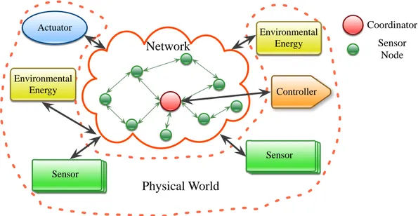
Figure 3.2 Illustration of the interaction between a WSN and the phys-ical world. . . 28
Figure 3.3 Structure of HarvWSNet. . . 33
Figure 3.4 General structure of the energy harvesting system. . . 34
Figure 3.5 Interactive co-simulation of WSNet and MATLAB. . . 35
Figure 3.6 Global architecture of the energy harvesting system. . . 37
Figure 3.8 Equivalent electrical circuit of a photovoltaic cell. . . 38
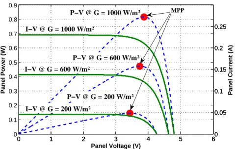
Figure 3.9 PV panel current-voltage and power-voltage characteristic. . 39
Figure 3.10 The electrical battery model. . . 40
Figure 3.11 Flowchart of the power manager. . . 41
Figure 3.12 Evolution of voltage in the energy harvesting system over 4 days. . . 42
Figure 3.13 Simulation set-up. . . 42
Figure 3.14 Estimated lifetime of each sensor node. . . 43
Figure 3.15 Wind-flow Energy Harvester Matlab Model. . . 45
Figure 3.16 Buck-boost converter efficiency ⌘MPPT as a function of out-put voltage V0(t)with switching frequency of 28kHz. . . 46
Figure 3.17 Supercapacitor Model proposed by [16]. . . 46
Figure 3.18 Efficiency of DC/DC boost converter block ⌘ as a function of output current IOUT. Measurements are from [17]. . . 47
Figure 3.19 In-tunnel channel attenuation model at 2.4 GHz. . . 48
Figure 3.20 Definition of transmission period. . . 50
Figure 3.21 Dedicated MAC protocol - Timeslot definition . . . 50
Figure 3.22 WSNet and Matlab Interaction. . . 52
Figure 3.23 Node position and network connectivity (last 13 nodes). . . 53
Figure 3.24 Total energy consumed per node over 24 hours . . . 54
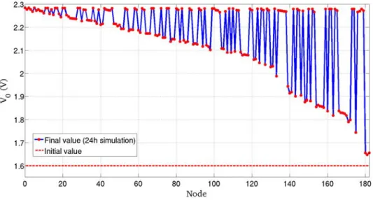
Figure 3.25 Supercapacitor voltage after 24h simulation. . . 54
Figure 3.26 Energy consumption per node state. . . 55
Figure 3.27 Transmission period of network with global PM. . . 55
Figure 4.1 Active mode current consumption in a typical WSN node [18] 58 Figure 4.2 Functional architecture of a typical sense & react RF transceiver. 60 Figure 4.3 Distribution of the current consumption in a transceiver: (a) receiver, (b) transmitter [19]. . . 61
Figure 4.4 Architecture of an SDR. . . 62
Figure 4.6 Conceptual diagram of the reconfigurable transceiver. . . 67
Figure 4.7 Conceptual diagram of the reconfiguration manager. . . 67
Figure 4.8 Conceptual diagram of the reconfigurable transmitter. . . . 69
Figure 4.9 Schematic of the reconfigurable PA. . . 69
Figure 4.10 Architecture of the reconfigurable receiver. . . 71
Figure 4.11 IIP3 versus power consumption in recently published LNAs. 73 Figure 4.12 Implementation of hardware LQE in the digital baseband. . 84
Figure 4.13 Variation of the reconfiguration metric LQEReconfig and the SINR as function of interference power in the case of inter-modulation presence and without interinter-modulation. . . 85
Figure 4.14 Variation of receiver power consumption as function of the desired signal and interference power. . . 86
Figure 4.15 LQEReconfig calculation for new hybrid LQE. . . 87
Figure 4.16 Combination of hardware and software LQEs. . . 87
Figure 4.17 Sequence diagram of transmission power adaptation. . . 88
Figure 4.18 Signal and interference scenarios. . . 89
Figure 4.19 Control algorithm using new hybrid LQE for a statically reconfigurable receiver . . . 91
Figure 4.20 Control algorithm for a continuous dynamically reconfig-urable receiver . . . 92
Figure 5.1 Simple block diagram of a wireless receiver. . . 98
Figure 5.2 Interference of adjacent radio channels. . . 99
Figure 5.3 Power spectrum of intermodulation product. . . 102
Figure 5.4 Simulation scenario. . . 104
Figure 5.5 Comparison of BER using different SINR models. . . 105
Figure 5.6 Simulation scenario used for analysis of PER under inter-modulation. . . 106
Figure 5.7 Effects of node density on PER with and without intermod-ulation. . . 107
Figure 5.8 Effect of reciprocal mixing due to the local oscillator phase noise. . . 108
Figure 5.9 EnvAdapt Architecture. . . 110
Figure 5.10 The XML configuration file used in EnvAdapt for a recon-figurable radio. . . 111
Figure 5.11 Interactions between the reconfigurable transmitter PHY layer and the other EnvAdapt layers. . . 112
Figure 5.12 Overview of the software architecture for the EnvAdapt re-ceiver PHY layer. . . 113
Figure 5.13 (a) Illustration of interference generated at node 1, (b) SINR computation at node 1. . . 114
Figure 5.14 Variation of SINR, LQEHW and power consumption for a continuous dynamically reconfigurable receiver . . . 117
Figure 5.15 Illustration of dynamic reconfiguration during packet re-ception with LQEHW calculation delay. . . 117
Figure 5.16 Dynamic reconfiguration algorithm. . . 118
Figure 5.17 Receiver static reconfiguration during packets reception. . . 118
Figure 5.18 Receiver static reconfiguration algorithm. . . 119
Figure 5.19 Transmitter reconfiguration algorithm. . . 120
Figure 5.20 Simulation scenario. . . 121
Figure 5.21 Simulation time-trace assuming dynamic reconfiguration. . 122
Figure 5.23 Impact of receiver dynamic and static reconfiguration on (a)
PRR and (b) energy consumption. . . 124
L I S T O F TA B L E S Table 2.1 eZ430-CC2500 consumption states. . . 12
Table 3.1 Train passage period. . . 50
Table 3.2 Network-level Power Manager Algorithm. . . 51
Table 3.3 Power consumption model. . . 51
Table 3.4 Default values of simulation parameters. . . 53
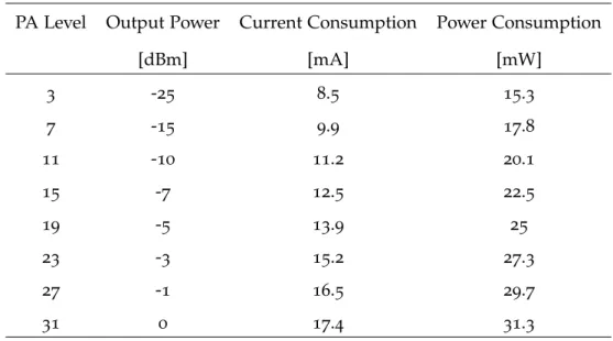
Table 4.1 TI CC2420 transmission power and corresponding current & power consumption. . . 64
Table 4.2 LNA characteristics from [20] (CMOS 0.18µm) . . . 65
Table 4.3 Power amplifier performances. . . 73
Table 4.4 LNA and Mixer Performances. . . 74
Table 4.5 VCO performances. . . 75
Table 4.6 ADC performances. . . 76
Table 4.7 Global receiver performances. . . 77
Table 5.1 PHY layer modeling in common simulation environments: NS, JiST/SWANS, GloMoSim, GTSNetS and WSNet [21]. . . 97
Table 5.2 Intermodulation products and their amplitudes. . . 101
1
M O T I V AT I O N , A N D C O N T R I B U T I O N S O F T H E T H E S I SThe beginning of the 90th was marked by the appearance of the internet as we know it today. The deployment of this heavy network contributed to the modifi-cation of our life positively. In the 2000, we assisted to the emergence of the web 2.0 and social networks. This internet targeting the "connection of humains" repre-sents a natural extension of internet in humain life. Y ears later, the idea of connect-ing everyday obj ects appeared naturally. This concept was mostly catalyz ed by the achievements of semiconductor industry with the miniaturiz ation of integrated circuits.
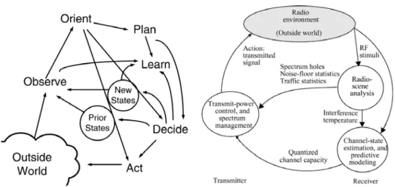
In 2005, the ITU ( International Telecommunication Unit) published a compre-hensive report on the "Internet of Things" ( IoT) and its expansion to real world and to obj ects from technical, economical and ethical views [ 1] . The main aim of the IoT is to integrate everyday obj ects that surround us to the virtual world of in-formation technology and make them a proactive actors of the internet. Figure1.1
shows the new "Any THING" axis where the thing- to- thing and Human- to- Thing connectivity is added to complete the Human- to- Human and Human- to- Machine interaction. This axis clearly opens up a new services opportunities and new infor-mation sources that will be introduced in the connected network.
1.1 motivation
1.1 motivation
IoT technology is expected to be a major growth field for both the semiconductor and internet markets. Such technology is expected to improve the productivity, efficiency, and security of various applications in our society [22]. Moreover, and more importantly, one of the most crucial building block of the IoT paradigm is wireless sensor networks (WSN) which consists of unattended nodes that sense the environment, collect data measurements, and relay them to a management entity. The major challenge facing the vision of IoT is to build large-scale autonomous WSNs that will interact with the objects and cloud services. In fact, WSNs are inherently resource-constrained components with a limited computational power, limited amount of memory, and short communication and sensing ranges [23]. All these constraints are often due to the limited storage capacity of a sensor node. The evolution of battery technologies is unable to follow the increasing process-ing and communication requierment of battery power devices such as WSNs. As shown in Figure1.2, there exists a huge gap between the energy density resulting from battery technology evolution, and the increasing energy requirements of pro-cessing devices. A major challenge therefore is to find another source of energy that can sustain sensor node operations such as energy harvesting.
has reached its capacity limit, lithium ion continues to make small gains. Although lithium ion has not yet hit the theoretical capacity limit, the industry consensus is that future gains will be unlikely to close the power gap. The limitations in the overall performance of lithium batteries depend on the intrinsic performances of the materials (anode, cathode, and electrolyte) and the technology aspects (material pro-cessing, electrode fabrication, and battery conception), taking into con-sideration of the environment of each material in the complete cell.
Lithium batteries are barely ade-quate for many of the demanding applications. Further performance enhancements are expected to be incremental. The path to these im-provements is through improved ma-terials, safety, and control electronics. The scale-up to large format batteries with capacities of the hundreds of Wh and KWh will need enhanced safety and packaging. While for small bat-teries the built-in safety measures are proven and well established, the requirements for notebook computers, power tools, and automotive applica-tion need to be reaffirmed and ensured.
safety electronics. Further advances are needed in engineering suitable safe materials systems without degrading other battery parameters.
Materials dictate the performance of portable energy sources. New materials hold the key to fundamental advances in energy conversion and storage. Nanostructured materials are becoming increasingly important for electrochemical energy storage. Na-nomaterials in particular offer unique properties as electrodes and electro-lytes for lithium batteries. There are several potential advantages associat-ed with the development of nanoelec-trodes for lithium batteries including the better accommodation of the strain of lithium insertion/removal, improving cycle life, higher electrode/ electrolyte contact area leading to higher charge/discharge rates, short path lengths for electronic and lithi-um ion transport leading to higher power, and new reactions not possible with bulk materials. Progress in lith-ium batteries relies as much on im-provements in the electrolyte as it does on the electrodes. Solid polymer electrolytes represent the ultimate in terms of desirable properties for
ionic conductivity of these materials at room temperature has prevented them from realizing their otherwise high promise. Though nanostructured materials offer a variety of advantages, the challenge lies in mitigating unde-sirable electrode/electrolyte reactions (due to high surface area) and finding easy and economically viable synthe-sis methods (as they are complex at present).
There are few alternatives for rechargeable batteries for portable electronics. Likely alternatives in-clude fuel cells and thin-film bat-teries. Unlike batteries, fuel cells are energy conversion devices. Projected specific energy and volumetric density for fuel cells are on par or superior to rechargeable batteries. While proton exchange membrane fuel cells are widely used in large capacity applica-tions, significant miniaturization of the fuel cell and associated components will be needed for their use in portable electronics. There have been large-scale investments in fuel cell related research, which should accelerate development of fuel cell technology for portable electronics. Another area that has witnessed significant recent activities is thin film rechargeable lithium batteries. Thin film batteries are solid-state devices with high energy density and cycle life. They use similar materials and chemistry found in lithium ion batteries, but utilizes thin film processing and integrated solu-tions to bring these to the substrate level. However, the technology has not yet reached into high volume manu-facturing. Despite the tremendous advances in fuel cells and thin-film batteries, there are no near-term solutions for the worsening energy gap. Battery technology has become a critical bottleneck in determining the overall performance of portable elec-tronics. Efficient power management techniques, battery efficient architec-tures, and the integration of low power drain components have become important aspects of mobile systems
Fig. 1.Relative improvement in the energy density of lithium ion batteries versus the areal density of hard disk drives and the number of transistors in Intel microprocessors (Data from Intel Corp, Matsushita Batteries, and Hitachi Storage Technologies).
Point of View
Figure 1.2: Relative improvement in the energy density of lithium ion batteries vs. the areal density of hard disk drives and the number of transistors in Intel micro-processors [2].
A typical sensor node such as eZ430-RF2500 [24] can last about 3 years on two AA batteries for a communication duty cycle of 1s. In real life applications, sensor nodes are required to last more than 15 years without service interruption. The energy consumption in sensor nodes is shared between the following components:
1.2 thesis contributions
(1) consumption due to sensor transducer, (2) consumption due to microcontroller processing, and, finally, (3) consumption due to the radio transceiver. The most energy hungry component in a sensor node is the radio transceiver, for example, Hill et al. [25] found that each bit transmitted by a sensor node consumes about as much power as executing 800 to 1000 instructions.
1.2 thesis contributions
The work presented in this thesis manly focuses on the lifetime issue of WSNs. With regard to the previously mentioned challenges facing the proliferation of WSNs and IoT, we describe in the following the main contributions of this thesis.
• Contribution 1: Simulation of Energy Harvesting WSNs - Chapter 3 In order to evaluate the deployment scenarios of energy harvesting sensor nodes, we propose, HarvWSNet, a co-simulation framework based on WSNet and MAT-LAB that provides adequate tools for evaluating energy-harvesting WSNs lifetime. The framework allows for the simulation of multi-node network scenarios while in-cluding a detailed description of each node’s energy harvesting and management subsystem, and its time-varying environmental parameters.
• Contribution 2: Power-Reconfigurable Transceiver for WSNs - Chapter 4 Wireless transceivers must perform adequately when the channel conditions are in worst case. However, when signal and interference conditions are favorable, the transceiver may consume more energy than required. Therefore, a recon- fig-urable transceiver (transmitter + receiver), able to adjust its corresponding power consumption to the time-varying signal and interference conditions, could have a decisive impact on the lifetime of the sensor node. In this chapter, we propose a reconfigurable transceiver model whose purpose is to enable the study of recon-figuration strategies for future environment- and energy-aware WSNs. The model used are based on Figure of Merits of measured circuits and can easily be im-plemented in a wireless network simulation in order to validate the value of a reconfigurable architecture in real-world deployment scenarios.
• Contribution 3: EnvAdapt Simulation Framework for Power Reconfigurable Transceivers - Chapter 5
We propose, EnvAdapt, a simulation framework for WSN, implementing the required models and reconfiguration strategies for tunable transceivers. The main objective of this framework is to evaluate the transceiver reconfiguration strategies and their impact on WSNs lifetime with respect to the channel models and other network protocols algorithms of the MAC and routing layers.
2
E N E R G Y I N A U T O N O M O U S W I R E L E S S S E N S O R N E T W O R K SContents
2.1 Introduction . . . 5
2.2 History of WSNs and Related Applications . . . 6
2.3 Requirements and Challenges of WSNs - Toward Autonomous WSNs . . . 9
2.4 Architecture of a WSN node . . . 10
2.5 Energy Harvesting and Storage in WSN . . . 13
2.5.1 Sources of Environmental Energy . . . 13
2.5.2 Energy Storage Components . . . 21
2.5.3 Architecture of Energy Management Systems for WSNs 21 2.6 Transceiver Power Consumption . . . 22
2.7 Conclusion . . . 24
2.1 introduction
With the recent advances achieved over the last decade in highly integrated micro-electronics, sensors and actuators, and low power wireless communication tech-nologies, wireless sensor networks (WSN) have gained significant interest from both academic and industrial communities due to their potential to monitor and control the physical world from remote locations which can be difficult to reach.
Wireless sensor networks (WSN) have an enormous potential for changing in-dustry function, enhancing people’s daily lives, and monitoring ecological envi-ronment. They have already been used in a wide variety of applications such as in-dustrial machine and process control, building and facility automation, fire rescue and medical monitoring, wild life tracking and agriculture monitoring. However, implementing such networks remains a challenging task due to hard requirements in terms of data processing and transmission capabilities as well as computational power and energy resources.
In this chapter, we present a general state of the art related to the major topics covered by this thesis: application domains of WSNs, energy-harvesting technolo-gies and power consumption issues in WSNs.
2.2 history of wsns and related applications
2.2 history of wsns and related applications
To understand the requirements and tradeoffs of WSNs, it is helpful to briefly ex-amine their origin and history. The early research and development in WSNs was initially driven by military applications. The first development of WSNs started at around 1980 by the Distributed Sensor Networks (DSN) program at the De-fense Advanced Research Projects Agency (DARPA) in the USA [26]. This research program explored the challenges involved in implementing many spatially dis-tributed low-cost and autonomous sensor nodes that collaborate with each other. The research results and testbeds generated many WSNs systems with uses mainly in the military domain. Examples of WSN applications include acoustic tracking sensors for low-flying aircrafts and Remote Battlefield Sensor Systems (REMBASS) [27]. At this time, the solutions proposed were very expensive and were dedicated only to military purposes. Even though researchers in the 1980s and early 1990s had in mind a global vision of a WSN, the processing workstations and commu-nications technologies were not yet available to support their goals. The WSN research remained in the defense area until the end of 1990s and early 2000s when the first low-cost sensor nodes were developed [28].
From these years onward, the increasing miniaturisation of microelectromechan-ical systems and radio frequency devices paved the way to a new era of mobile networks and resulted in the emergence of many other potential applications, ranging from industrial to health care. One outcome of these advances was the Smart Dust project [28] developed at the University of California at Los Angeles, which focused on the development of highly miniature sensor nodes called motes. This project demonstrated that a complete system composed of a micro-controller, wireless transceiver, sensors, and interface circuits can be integrated in a single tiny CMOS chip that has the size of a grain of sand. Another research effort was the PicoRadio project [29] initiated in 1999 to support the development of low-cost and low-energy ad-hoc wireless networks that can power themselves from the en-ergy sources available in their operating environment, such as vibrational or solar energy.
During the same time, the IEEE catalyzed the development of WSNs by defining the new IEEE 802.15.4 standard targeting low cost, low-power and low-data rate wireless personal networks. This standard defined the specifications of new wire-less Medium Access Control (MAC) and Physical layer (PHY). To stimulate the WSN market, a group of companies formed an alliance called the ZigBee Alliance that focuses on the development of the ZigBee protocols based on IEEE 802.15.4 standard. The main objective of the ZigBee Alliance is to describe a protocol stack
2.2 history of wsns and related applic ations
architecture that guarantees interoperability among devices produced by different companies. In addition to Z igBee, many other standards have been proposed such as Enocean, 6LoPAN, W ireless HART, ANT, RF4CE, etc. [30] .
Currently, W SNs are viewed as the most important technology of the 21st cen-tury due to the variety of possible applications [ 26] . A W SN may consist of many types of sensors that monitor different physical information including humidity, temperature, light, movement, mechanical stress, etc. As shown in Figure 2.1 [3] , a huge number of applications are possible.
Figure 2.1: Future applications of W SNs [3] .
These applications can be broken down into five main categories ( Figure2.2) : in-dustrial, home monitoring, health care, environmental, and military applications. • Industrial applications: The industrial sector is continuously looking for
more efficient ways to improve production q uality and reduce costs while minimiz ing waste of energy and materials. Thus, it is not surprising that several organiz ations, such as CISCO [31] , are excited about the possibili-ties of using W SNs to monitor and enhance each step of product including production, delivery and consumption. Sensor nodes can offer real- time ac-cess to information about eq uipment or plants, and prevent disruption of infrastructures [ 32] . Unlike wired networks, W SNs are excellent candidates for monitoring of the entire life of a product, step by step from raw material
2.2 history of wsns and related applications WSNs Applications Industrial Health Environmental Home Military
Figure 2.2: Application domains of WSNs.
provision used for its fabrication to its final assembling. The equipment to be monitored by WSNs can include assembly machines [33], product parts, logistics and transportation (containers or vehicles) [34], warehouses palettes localisation [35], and end-user assets.
• Home monitoring: The field of home monitoring represents another poten-tial area for using WSNs. Sensor nodes can transform a traditional home into a "smart home" that is aware of its occupants’ special needs and respond accordingly. A future smart home will be able to regulate the rooms’ tem-perature, control air quality, adjust lighting, and even play music that fits with a particular resident. This automation would obviously minimize the building’s energy consumption as-well. Sensor networks can also improve the security of the house by sending an alarm message to the resident when it detects intruders, gas leakage, fire occurrence or other security incidents. Moreover, a smart home may even be able to provide data to firefighters about structural integrity of the building and prevent areas that may collapse. The flexibility and easy installation of WSNs can ease the implementation of such houses and contribute to the digital future of humanity.
• Health care: WSN technology could potentially provide better health-care delivery for different segments of the population. Health professionals are always looking for new techniques that provide the best care to patients. Thus, WSNs may change the interaction between the medical staff and their patients. The medical domain has produced many implementations of sen-sor nodes ranging from equipment and patient health monitoring to wireless medicine injection and control [36]. There are many health monitoring
prod-2.3 requirements and challenges of wsns - toward autonomous wsns
ucts implementing WSNs such as SmartVest [37], AMON [38], Wealthy [39]. These systems transmit wirelessly and continuously physiological parame-ters about the health of the patient (e.g. monitoring of vital signs, blood glucose, organ monitor, cancer detector [23], etc.) so that the health care pro-fessionals can diagnose and assure timely interventions.
• Environmental monitoring: The growing concerns about ecology and the impact of humanity on climate change and global warming is pushing scien-tists to use WSNs for environment protection. WSNs can facilitate the mea-surement of a large variety of environmental data [40] for a huge number of applications such as agriculture, meteorology, geology, zoology, etc. The advantage of using WSNs in such applications is mainly due to the need for acquiring large amounts of data in each region that would be difficult to obtain using existing technologies. Based on this data, researchers and engineers can build efficient models that can describe the behavior of the environment and potentially predict disasters.
• Military applications: As stated previously, the beginning of WSNs devel-opment focused on military applications [41]. One of the most important characteristics of WSNs that make them prominent for military applications is their ability to autonomously reorganize themselves to form a network capable of routing measurement data to the commanders. From defense’s perspective, WSNs represent an important technology necessary for main-taining soldiers safe in the battlefield [42]. In addition, WSNs could provide more useful information such as enemy troop movement detection, moni-tor the health of soldiers, coordinate resources and defense, gunfire origin detection, monitor critical equipment, etc.
Today, many of the WSNs applications described in this section are widespread. Given the usefulness of such networks in our lives, WSNs will continue their pro-liferation in every domain, and the number of their applications in the future will be limited only by imagination [43]. In this section, we reviewed the history and some of the well-known WSNs applications. More specifically, we considered five application fields namely industrial, home monitoring, healthcare, environmental, and military. In the next section, we present the architecture of a sensor node architecture and the corresponding building-blocks.
2.3 requirements and challenges of wsns - toward autonomous wsns
In this section, we focus on the requirements and challenges facing the building and deployment of WSNs. As discussed in the previous sections, in order to
han-2.4 architecture of a wsn node
dle a wide range of applications types, an autonomous sensor node hardware and implementation is required to address the following requirements:
• Low Cost: The utility and scalability of a WSN highly depends on its density, which means large numbers of sensor nodes in the deployment area. There-fore, to make the deployment cost effective, the cost of individual sensor nodes should be extremely low.
• Low Power: For high density WSNs, battery replacement can be difficult, expensive, or even impossible in harsh environments. Nodes must be able to ensure a permanent connectivity and coverage for long periods, ideally up to 10 years, without service interruption.
• Small Size: WSNs are desired to replace cables that are often impracticable. Therefore, the size of the sensor node must be small enough so that the WSN monitors the environment in an unobtrusive and transparent manner. The real requirements and challenges of a WSN heavily depends on the ap-plication domain. Nevertheless, many apap-plications are concerned with two main challenges that will be addressed in this thesis. Firstly, since most sensor nodes are battery-powered, it is important to tackle the limitations of batteries and their replacement. Thus, to guarantee an energy autonomy for sensor nodes, energy harvesting represents an efficient solution that may results in a self-powered node. Secondly, reducing the excessive power consumption of the radio transceiver is of primary importance to assure a long lifetime to networks that are unable to harvest energy from their environment or that harvest very little energy or in an intermittent manner.
2.4 architecture of a wsn node
As shown in Figure2.3, a sensor node is composed of four major blocks: processing unit, communication interface, sensors and power supply.
• Microcontroller: Since the main functionalities of a sensor node consists in communicating, processing and gathering sensor data, sensor nodes must be equipped with a microcontroller unit (MCU). The MCU is responsible for execution of algorithms and communication protocols, controlling of the sensor and actuators, processing of gathered data, and it can be used also for the management of the energy harvesting block [44]. The MCU is required to be energy-efficient with a very short wake-up time.
• Transceiver: Wireless communications between sensor nodes and also with the base station are carried by means of a wireless transceiver interface. A
2.4 arc hitec ture of a wsn node Power Supply Energy Storage Power Management Energy Harvesting Sensor/Transducer Radio Transceiver Microcontroller Environment Parameters (Heat, motion, irradiance, etc.)
Figure 2.3: Block diagram of a sensor node.
wireless transceiver implements all the necessary functionalities to convert bits data to radio waves and vice- versa. There exists many wireless stan-dards operating in different freq uency bands such as Z igBee, Bluetooth Low Energy ( BLE) , Ultra- W ide Band ( UW B) , etc.
• Sensors and actuators: Environment and target application is monitored us-ing sensors which are responsible of convertus-ing physical world information into electrical signals. There exists a plethora of sensor nodes that measure environmental parameters such as light, temperature, gas content in the air, sound, etc. These sensors can be classified as either analog or digital depend-ing on the characteristics and speed req uirements of the microcontroller and actuators used.
• Power supply: The power supply block has the functionality of supplying the req uired energy to power the sensor node. W hile typically consisting of a battery, it might also consists of an energy harvesting block which scav-enges environmental energy, a power manager which is usually based on DC- DC converters that regulate the harvested energy, and finally a storage element responsible for storing the energy needed by the sensor node when the environmental energy to harvest is unavailable.
ex ample: simplic iti sensor node
In order to assess the lifetime issue in a W SN, we consider the TI eZ 430- RF2500 sensor node which combines the MSP430 MCU and the CC2500 low power radio
2.4 arc hitec ture of a wsn node
transceiver. This node consumes about 6- 10µA during deep sleep mode and 15-20mA in full operation mode. Figure 2.4 shows the current consumption profile of the sensor node during temperature measurement and data transmission to a base station. 0 0.5 1 1.5 2 2.5 3 0 5 10 15 20 Time [ms]
Current Consumption [mA]
3
0.5 0
0 1 2
1 2 3 4 5 6 7 8 9 10 11
Figure 2.4: Current consumption profile of the eZ 430- CC2500 platform.
1 Temperature Measurement
2 V cc Measurement
3 Temperature & V cc Calculation 4 O scillator activation 5 Transceiver Power O n
6 Data prepare
7 PLL synchroniz ation 8 Clear channel assessment 9 Rx to Tx switching
10 Data Tx
11 Sleep mode switching
Table 2.1: eZ 430- CC2500 consumption states.
The execution time of this application is about 2.8ms and the average current consumed by the sensor node IO N- avg is 12.33mA. To assess the lifetime of the application, we consider two AAA batteries with a nominal capacity of 1000mAh. The application lifetime is calculated by:
2.5 energy harvesting and storage in wsn
Application Lifetime = Cbattery IApplication-avg =
1000[mAh]
12.33 [mA] (2.1)
' 3 days
To reduce this excessive current consumption, the sensor node should reduce the amount of transmission of its temperature measurement to a base station (i.e. at a period of 1 second). Thus, the sensor node lifetime is given by:
Application Lifetime = Cbattery IApplication-avg =
1000[mAh] (ION-avg⇥tON)+(IOFF-avg⇥tOFF)
tON)+tOFF)
(2.2) = (12.33[mA]⇥2.88[ms])+(1.3[µA]⇥(1[s]-2.88[ms]))1000[mAh]
1[s] ' 3 years
In this example, the calculated lifetime of the sensor node is 3 years. This result seems to be overestimated for two reasons: The first one is due to the hypothesis that the battery voltage is always sufficient to supply the sensor node. The second is related to the leakage of the battery which was not taken into account. This example clearly shows that a network supplied only by batteries has a very lim-ited lifespan. Therefore, in order to maximize network operation without battery replacement, it is necessary to reduce the power consumption of each component of the sensor node or add an additional energy source such as energy harvesting. 2.5 energy harvesting and storage in wsn
Energy harvesting is a technique where ambient energy is captured from multiple sources and converted into electrical energy. During the last decades, solar and wind energy have been widely used to provide electrical energy to industry and ur-ban applications due to their high power yield. Recently, researchers have actively investigated the adaptation of such renewable energies to WSNs. Since WSNs are expected to be deployed in harsh or inaccessible environments for many years, several research works have focused on the diversification of energy sources for powering autonomous sensor nodes. In this section, we briefly overview existing environmental energy sources and storage elements for WSNs.
2.5.1 Sources of Environmental Energy
Environmental energy harvesting represents a viable option to increase the au-tonomy of WSNs where batteries are hard or impossible to recharge or replace.
2.5 energy harvesting and storage in wsn
Several factors make them a key choice for perennial operation of sensor nodes: (1) The recent advancement in low-power electronics has significantly reduced the power consumption of sensor nodes. Hence, ambient harvested energy may provide a long-term solution and reduce the dependency on batteries. (2) Energy autonomous WSNs are easy to install and do not require any wiring cables. Conse-quently, the heavy installation cost and battery replacement can be reduced greatly [45]. There are various sources of ambient energy available for energy harvesting as shown in Figure 2.5. These energy sources can be categorized into five types: mechanical, thermal, solar, wind, and radiofrequency.
P1: Naresh Chandra
December 18, 2012 15:18 K10744 K14160˙C001
20
Energy Harvesting Autonomous Sensor Systems
AC Rotary Generator AC Linear Generator Electrostatic Generator Electromagnetic Generator Power/ Energy Conditioning Energy
Storage ElectricalLoad
Induction Coil Alternating B-Field: Power Transmission
Lines
Wireless Power Transfer via Strongly Coupled Magnetic Resonances Ambient Radio Frequency Waves Mechanical Vibration Pressure Piezoelectric Element Electrochemical Reaction Thermoelectric Generator Photovoltaic Cell Antenna/ Rectenna Microwave Radiation Artificial
Lighting RadiationSolar Thermal Gradient Biochemical Hydro Wind Compressed Gases Ocean Wave Autophagous Structure-Power Combustion FIGURE 1.15
Energy harvesting sources and their energy harvesters. (Adapted from J.P. Thomas, M.A. Qid-wai, and J.C. Kellogg, “Energy scavenging for small-scale unmanned systems,” Journal of Power
Sources, vol.159, pp. 1494–1509, 2006 [27].)
renewable energy sources available at the specific application areas, like an
outdoor bright sunny day with a rich amount of solar energy, along a coastal
area with a lot of wind energy, on a bridge structure with travelling vehicles
and strong vibrations, and so on. In addition, there could also be the
possibil-ity of two or more energy sources available for harvesting at the same time.
As such, EH technology can provide numerous benefits to the end user, and
some of the major benefits of EH suitable for WSNs are stated and elaborated
in the following list [27, 28]. An EH solution can do the following:
1. Reduce the dependency on battery power. With the advancement of
microelectronics technology, power consumption of the sensor nodes
is decreasing, hence, harvested ambient/environmental energy may
be sufficient to eliminate the battery completely.
2. Reduce installation cost. Self-powered wireless sensor nodes do not
require power cable wiring and conduits; hence, they are very easy
to install and reduce the high installation cost.
3. Reduce maintenance cost. EH allows for the sensor nodes to function
unattended once deployed and eliminates service visits to replace
Figure 2.5: Energy harvesting sources and their energy harvesters [4].
2.5.1.1 Solar Energy Harvesting
Solar energy is the most popular ambient energy due to its high power density [46]. Consequently, a huge number of research work has focused on the design of micro-solar PV and energy harvesting hardware to efficiently make use of micro-solar energy [6] [5] [8]. Solar harvesting consists in converting the incident light into electrical power using photovoltaic (PV) panels. Figure 2.6 shows a typical solar energy harvester which consists of a PV panel and DC-DC converter that maximizes the energy transfer to a load.
The two first prototypes of solar harvesting sensor nodes were Heliomote [6] and Prometheus [5]. In these systems, built with off-the shelf components, the solar panel is directly connected to the storage device (supercapacitor & Li-ion
2.5 energ y harvesting and storag e in wsn Load DC-DC Converter
Switching Converter
(Buck or Buck-Boost)
Battery or
Supercapacitor
Module
Solar
Irradiance
PV
Module
Figure 2.6: Simple diagram of a solar energy harvester.
battery in Prometheus, and NiHM battery in Heliomote) . The Prometheus and Heliomote systems are depicted in Figure 2.7.
( a) Heliomote [6] . ( b) Prometheus [5] .
Figure 2.7: Examples of solar energy harvesting sensor nodes ( a) Prometheus [ 5] and ( b) Heliomote [ 6] .
To achieve a high conversion efficiency, a power management system is req uired in order to adapt the operating point of the PV panel to the variations of light con-ditions, so that the maximum power ( PMPP) is always maintained. Everlast and Ambimax are examples of solar energy harvesting sensor nodes implementing such power management systems. The Everlast sensor node implements a system that estimates the maximum voltage power point ( VMPP) based on the open- circuit voltage ( VOC) of the solar panel. The global architecture of this system is repre-sented in Figure2.8. The pulse freq uency modulated ( PFM) regulator consists of a buck- converter and a step- up regulator. Its main function is to transfer the energy to the supercapacitor stage. The Everlast sensor node claims a lifetime of 20 years at a duty cycle of 50 % and a data rate of 1 Mbits/s.
Ambimax [8] ( Figure2.9) is a sensor node which obtains its energy from both solar and wind harvesting systems. The MPPT system of Ambimax uses a
photo-2.5 energy harvesting and storage in wsn
448 IEEE COMMUNICATIONS SURVEYS & TUTORIALS, VOL. 13, NO. 3, THIRD QUARTER 2011
control Switch Shutdown voltage Reference voltage Regulated CONVERTER BUCK PFM CONTROLLER STEP UP PFM REGULATOR REGULATOR Shutdown Vsolar CAPACITOR SUPER Vcap SOLAR CELL
Fig. 4. Block diagram of Everlast’s energy harvesting subsystem[34].
perform harvesting-aware performance adaptation. An analysis of the heliomote harvesting architecture shows that if the battery size is enough to accommodate the variability in harvested energy and the rate of consumption of power is less than the rate of sourced power, then perpetual operation can be achieved. A thorough and complete mathematical analysis of these conditions is presented in [20]. Section IV discusses in more detail, the implications of energy harvesting on wireless sensor node applications.
Fleck1[46] is also a single-stage-storage solar energy har-vesting system using NiMH batteries. Fleck1 is an integrated node and uses an ATmega128[47] processor and Nordic nRF903 radio chip[48] (operating at 433MHz). The solar panel measures 100cm2 and outputs 2100mWh/day. Experiments with Fleck1 showed that using a DC-DC converter or regulator to power the node from the battery is useful because it allows the node to be powered for longer, powering the circuit even at low voltage like 1.2V. This is especially useful if the node is batteryless, i.e., uses super-capacitors instead of batteries.
2) Nodes with Supercapacitor-based Storage: Everlast[34] is a supercapacitor-operated wireless sensor node and does not use batteries for energy storage. It attempts to break the performance-lifetime trade off by using a 100F super-capacitor having 300J energy storage, a low supply current MCU (PIC16LF747[49] - from 25µA at 31.25kHz to 930µA at 8MHz) and a low power transceiver supporting 1Mbps data stream (Nordic nRF2401[50] - 0dBm power, typically 13mA supply current at 3V). Everlast is an integrated system with sensors, radio, micro-controller and the energy harvesting sub-system, unlike Heliomote and HydroWatch, which are add-ons for existing platforms. Figure 4 shows the block diagram of the energy harvesting sub-system of Everlast.
As shown in Figure 4, the components of Everlast’s energy scavenging subsystem are: a solar cell, a super-capacitor, PFM controller and PFM regulator. Everlast uses a pulse frequency modulated (PFM) regulator to charge the super-capacitor. The function of the PFM regulator is to charge a capacitor and then transfer the energy to the output load super-capacitor. The PFM regulator consists of a buck converter and a
step-Fig. 5. Prometheus energy harvesting architecture [25].
up regulator. Connecting a super-capacitor directly to the solar panel results in the solar voltage falling to the super-capacitor voltage, instead of the super-super-capacitor charging up. So a switched-capacitor circuit (with a smaller capacitor of 1µF) and buck converter is used to efficiently charge the load super-capacitor of 100F. When the solar voltage exceeds the specified reference VMP P5, the PFM controller (comparator) pulses the PFM regulator, denoted as “Switch control” signal in Figure 4. This causes flow of charge from input capacitor into the buck converter’s inductor and into the load super-capacitor, thus charging it. Once the super-capacitor is fully charged, the PFM controller shuts down the PFM regulator by comparing its voltage to a 2.5V reference voltage and sending the “Shutdown” signal. Using this technique, Everlast claims a lifetime of 20 years at 50% duty cycle and 1Mbps data rate. Solar-Biscuit[51] is another example of a solar-energy har-vesting node using super-capacitors. It is an integrated node and uses the PIC 18LF452 microchip[52] and a Chipcon CC1000 radio[53]. A 5V, 1F super-capacitor is directly con-nected to the 5cm⇥ 5cm solar-panel. Unlike Everlast, Solar-Biscuit has no regulation of voltage on input or output sides of the (super-capacitor) storage.
Sunflower[35] is another implementation of a solar energy harvesting node that uses super-capacitors. It uses four PIN photo diodes, a miniature super-capacitor (0.2F) and has a form-factor of 0.9 inch⇥ 1.2 inch. It uses a MSP430F1232 microcontroller[54] which has a power draw of 540µW when active, at a operating voltage of 2.7V. Similar to Everlast, Sunflower employs a switching regulator to charge the super-capacitor from the photo diodes.
3) Nodes with Tiered Storage: Prometheus [25] is a double-storage energy harvesting system for scavenging solar energy using the TelosB platform[43], [45]. It uses two 22F super-capacitors in series as primary storage and a 200mAh Lithium polymer battery as the secondary storage. A solar panel measuring 3.23in⇥ 1.45in with a power output of 130mW, is used to charge the super-capacitors. During times of excess
5MPP (Maximal Power Point) is the voltage and current combination that
maximizes power output under given sunlight and temperature conditions and VM P P is the voltage at MPP.
(a) Block diagram of the Everlast’s energy har-vesting subsystem [7].
(b) Everlast prototype board [7].
Figure 2.8: The Everlast prototype node and its block diagram [7].
sensor to detect the ambient light conditions coupled with a hysteresis comparator that forces the solar panel to work in its maximum power point.
(a) Ambimax sensor node [8]. (b) Ambimax hardware board [8].
Figure 2.9: The Ambimax prototype node and its hardware board [8].
PowWow [9] is an energy harvesting sensor node based on an MSP430 micro-controller and a CC2420 RF transceiver. This sensor node has the ability to harvest energy from solar and thermal energy using a power manager based on based on the LTC3108. This power manager adapts the sensor node communication duty cycle according to the estimation of harvested energy and the consumed energy provided by an energy monitor. The experiments showed that the thermal energy-harvesting system [47] can power the sensor node using the wasted heat of a personal computer adapter.
These sensor nodes prototypes have successfully proven that solar energy har-vesting is able to provide electrical power to wireless sensor nodes. In practice however, implementation of a solar energy harvesting system must take into
ac-2.5 energ y harvesting and storag e in wsn
Figure 2.10: Generic architecture of the PowW ow sensor node [ 9] .
count many factors such as availability of the light source, electrical characteristics and the siz e of the PV cell used, capacity of the storage element, and power con-sumption of the other sensor node components.
2.5.1.2 Wind Energy Harvesting
Similarly to solar energy, wind energy harvesting has been widely used for high-power applications where wide turbines are used to generate electrical energy. In the W SNs context, there has been only few research efforts that attempt to develop small scale wind energy harvesters to power W SNs deployed in indoor applica-tions such as underground tunnels. In these research works, we distinguish two approaches for wind energy harvesting: The first one is a direct approach where traditional wind turbines are used, and the second one is an indirect approach which uses piez oelectric materials to generate electrical power from air- fl ow en-ergy.
The Ambimax sensor node [8] ( Figure2.9) and the work presented in [48] uses a direct approach to sustain electrical power for the sensor node. The results have shown promising results of power densities that can be harvested from air velocity. The global architecture of a wind energy harvester is represented in Figure 2.11. It consists of three main blocks: ( 1) a wind turbine coupled with an electrical generator, ( 2) a power management unit, which consists of power conditioning circuitry ( AC- DC/DC- DC converters and MPPT) and energy storage stage, and ( 3) the sensor node which consists of a microcontroller, sensors, and radio transceiver.
Similarly, in other research works, Priya et al. [10] have developed a windmill that uses a piez oelectric bimorph transducer to generate electricity from air- fl ow energy. Figure2.12shows the schematic of the piez oelectric bimorph and the fab-ricated windmill.
2.5 energy harvesting and storage in wsn P1: Naresh Chandra
December 14, 2012 9:58 K10744 K14160˙C002
38
Energy Harvesting Autonomous Sensor Systems
sensor node, and able to harvest sufficient energy from weak and uncertain
wind energy sources to sustain the operation of the sensor node for a long
period of time.
2.1 Direct Wind Energy Harvesting (WEH) Approach
Using a Wind Turbine Generator
To better understand the functionality and performance of the direct WEH
system, the circuit architecture of a wind-powered wireless sensor node is
presented in
Figure 2.1
. The wind-powered sensor node in
Figure 2.1
con-sists of three main building blocks: (1) an energy harvester incorporating the
wind turbine coupled to the electrical generator; (2) a power management
unit, which consists of a power conditioning circuit and energy storage, and
(3) the wireless sensor node itself.
For a space-efficient WEH system operating at low wind speeds, the AC
(al-ternating current) voltage V
p(peak), generated by the wind turbine generator
is in the range of 1 to 3 V, which is relatively smaller than that of the large wind
turbine with a megawatt power rating and an output voltage of hundreds of
volts [55]. It is thus challenging for the AC-DC (direct current) rectifier using
conventional silicon-based diodes, which has a high on-state voltage drop V
onof 0.7 to 1 V, to rectify and convert the low-amplitude AC voltage into a form
usable by the electronic circuits. Based on the instantaneous output DC
volt-age given by V
dc= V
p− 2 ∗ V
on, it can be seen that the efficiency of the AC-DC
rectifier using diodes is especially low for the small-scale WEH system. To
overcome this challenge, metal-oxide-semiconductor field-effect transistors
(MOSFETs) are used in place of the conventional diodes because the voltage
drop across a MOSFET is smaller than that with a diode. A MOSFET-based
active rectifier using comparators to sense the zero crossings of the input AC
voltage has been proposed in the literature [63–65] to achieve high AC-DC
power conversion efficiency in very-low-voltage applications. The problem
Zs Wind Turbine Generator AC-DC Active MOSFET Rectifier MPP Tracking Boost Converter Energy Storage (Batteries/ Supercap)
Voltage and Current Sensing Circuit +3V DC-DC Regulating Buck Converter External Sensors (i.e., temperature) ADC 2.4 GHz Wireless Transceiver Microcontroller and Its Peripherals gnd Wireless Sensor Node
PWM Generation Circuit Conventional Battery-Operated
Wireless Sensor Node Power Management Unit
νs
FIGURE 2.1
Functional block diagram of a wind energy harvesting (WEH) wireless sensor node.Figure 2.11: Block diagram of a wind energy harvesting for wireless sensor node [8].
the resonance a piezoelectric material with high figure of merit (d.g) was selected. Table I shows the material constants for the conventional hard and soft ceramics. It can be clearly seen from this table that soft materials have higher figure of merit and consequently APC 855 was selected as the transducer material.
Piezoelectric bimorph transducer structure was selected because of the following advantages in terms of suitability for windmill:
1. Bimorphs have enough mechanical strength in the high vibration conditions of frequency 1–10 Hz. In this limit the applied load on the bimorph can be of the order of few newtons. Laboratory scale measurements have shown that a bimorph vibrating under a force of 2 N at low frequencies of 10 Hz do not suffer from any mechanical degradation.
2. The piezoelectric voltage coefficient of bimorph is high so the charge developed under fully loaded condition is high.
3. The maximum displacement of the bimorph is signifi-cant due to the high level of bending force that can be applied. Hence, the mechanical energy that can be transferred to the bimorph is high.
4. The manufacturing cost of bimorph is very low. Figure 1 shows the picture of the fabricated windmill. Twelve bimorph transducers were arranged around the circumference of the center shaft as shown in Fig. 2 in a pipe of diameter 114 mm and width 60 mm. Each bimorph was adjusted such that it just touches the tip of the triangular stopper. The dimensions of each individual bimorph were 60 ! 20 ! 0:6 mm3 with a free length of 53 mm. The
resonance frequency and capacitance for this size of bimorph was measured to be 65 Hz and 170 nF respectively. The displacement of the bimorph under the maximum torque was equal to the gap between the stoppers and thus it oscillates between these gaps. As the bimorph is pressed against the stopper it produces charge through direct piezoelectric effect. Thus, continuous back and forth oscillation of bimorph between the two stoppers will continuously generate electricity. The transducer bearings were designed to be with very low friction. The structure shown in Fig. 2 was mounted on a central windmill shaft as shown in Fig. 3(a). The windmill shaft was rotated by the motion of the wind using the camshaft mechanism as shown in Fig. 3(b). The wind flow causes the fan to rotate. The torque generated from the rotation of the fan is transferred to the windmill shaft by using a cam of height equal to the circumferential distance between the two stoppers and a hanging weight of 23.5 gm in the form of beam. Thus, rotation of the fan results in generation of the oscillatory motion of the weight (similar to pendulum) and this motion is transferred to the windmill shaft which oscillates the stoppers.
The working prototype shown in Fig. 1 was evaluated for its performance. After the completion of the windmill assembly it was found that one of the bimorph had an electrode delamination and other eleven were fully func-tional. Hence, these eleven bimorphs were used for the measurement. Before the operation of the windmill, the bimorphs were pre stressed to have a bending of 1.77 mm at the tip touching the stopper. The output power increases with the prestress level however the rotation of the fan becomes proportionately difficult. Thus, the pre stress level was adjusted such that the fan could be rotated easily in the normal wind flow conditions. Figure 4(a) shows the signal waveform generated from the windmill at the frequency of 4.2 Hz measured across the 4.6 k! resistor. A peak voltage
Table I. Piezoelectric constants of the hard and soft ceramics.
Properties APC 840 APC 850 APC 855
"X 33="o 1000 1750 3250 "X 11="o 1100 1594 3465 "d31(pC/N) 93 175 270 d33(pC/N) 218 400 580 g33(10"3m2/C) 24.6 26 19.5 "g31(10"3m2/C) 9.5 12.4 8.8 g33.d33(10"15m2/N) 5362.8 10400 11310 g31.d31(10"15m2/N) 883.5 2170 2376 Qm 500 80 75 Piezoelectric bimorph PVC Plastic Ball bearing Windmill Shaft Stopper
Fig. 2. Schematic of the piezoelectric bimorph arrangement in the windmill and the method for applying oscillatory stress.
Jpn. J. Appl. Phys., Vol. 44, No. 3 (2005) Express Letter S. PRIYAet al. L 105
(a) Piezoelectric bimorph transducer. (b) Piezoelectric windmill prototype.
Figure 2.12: Piezoelectric bimorph and windmill prototype used for wind energy harvest-ing [10].
The power densities delivered by air-flow harvesters may exceed the required energy by a sensor node, thus, an adequate power management system is manda-tory to regulate the power delivered by these systems. However, the size of the wind turbine is still an obstacle for the proliferation of wind energy harvesters compared to the dimension of a sensor node.
2.5.1.3 Thermoelectric Energy Harvesting
Thermal energy is the most abundant and is found in many applications and environments. Typical examples of these include heat from industrial machines, home appliances, vehicle exhausts, human body [49], etc. Converting such energy into electrical energy may lead to the highly desirable self-powered WSNs. In this context, thermoelectric generators (TEG) were developed in order to produce electrical power from heat flow by exploiting two main effects: Seebeck and Peltier effects.

![Figure 2.10: Generic architecture of the PowW ow sensor node [ 9] .](https://thumb-eu.123doks.com/thumbv2/123doknet/11503986.293769/32.892.224.639.104.362/figure-generic-architecture-poww-ow-sensor-node.webp)