HAL Id: hal-01373433
https://hal.archives-ouvertes.fr/hal-01373433
Submitted on 28 Sep 2016
HAL is a multi-disciplinary open access
archive for the deposit and dissemination of sci-entific research documents, whether they are pub-lished or not. The documents may come from teaching and research institutions in France or abroad, or from public or private research centers.
L’archive ouverte pluridisciplinaire HAL, est destinée au dépôt et à la diffusion de documents scientifiques de niveau recherche, publiés ou non, émanant des établissements d’enseignement et de recherche français ou étrangers, des laboratoires publics ou privés.
addresses
Aymen Boudguiga, Tony Cheneau, Maryline Laurent
To cite this version:
Aymen Boudguiga, Tony Cheneau, Maryline Laurent. Usage and performance of cryptographically generated addresses. [Research Report] Dépt. Logiciels-Réseaux (Institut Mines-Télécom-Télécom SudParis); Services répartis, Architectures, MOdélisation, Validation, Administration des Réseaux (Institut Mines-Télécom-Télécom SudParis-CNRS). 2008, pp.94. �hal-01373433�
Usage and Performance of
Cryptographically Generated
Addresses
Authors:
Aymen BOUDGUIGA Tony CHENEAU Maryline LAURENT-MAKNAVICIUS
Department: Software and Networks
Reference: 08015-LOR
Neighbor Discovery (ND) controls IPv6 nodes and routers interactions through ICMPv6 messages. It provides address resolution and duplicated address detection. Nonetheless, it does not offer security protection to the exchanged messages. In order to improve its security, Secure Neighbor Discovery (SEND) has been specified using the same ND messages and adding new options providing authentication and replay attacks control. SEND uses Cryptographically Generated Addresses (CGAs) as IPv6 addresses and RSA as key and signature generation algorithm.
CGAs are created using RSA public key. In fact, they contain a cryptographic based identifier. Their interface identifier is generated using SHA-1 hash function over a param-eters structure which contains the generating node’s public key. Our project consists on the study of CGAs different usages in wired, multihoming and mobile networks. In addi-tion, we studied CGA generation and verification algorithms performance and improve it with the use of Elliptic Curve Cryptography (ECC). We generated and conducted a set of tests to assess CGA generation performance in different platforms. Moreover, through a set of experiments, we evaluated the potential brought by ECC in cryptographic address generation.
Maryline LAURENT-MAKNAVICIUS Professor
TELECOM & Management SudParis Department LOR 9 rue Charles Fourier 91011 Evry cedex
E-mail: [email protected] Tony CHENEAU
PhD student
TELECOM & Management SudParis Department LOR 9 rue Charles Fourier 91011 Evry cedex
E-mail: [email protected] Aymen BOUDGUIGA
Internship student
TELECOM & Management SudParis Department LOR 9 rue Charles Fourier 91011 Evry cedex
Abstract . . . i
List of figures . . . vii
List of tables . . . viii
List of acronyms . . . ix
Introduction 1 1 Securing Neighbor Discovery 3 1.1 Neighbor discovery (ND) . . . 3
1.1.1 ND messages . . . 4
1.1.1.1 Router solicitation (RS) . . . 4
1.1.1.2 Router advertissement (RA) . . . 4
1.1.1.3 Neighbor solicitation (NS) . . . 5
1.1.1.4 Neighbor advertisement (NA) . . . 5
1.1.1.5 Redirect . . . 6
1.1.2 ND options . . . 6
1.1.2.1 Source/Target link layer address . . . 6
1.1.2.2 Information about the prefix . . . 7
1.1.2.3 Redirected header . . . 7
1.1.2.4 MTU . . . 8
1.1.3 ND applications . . . 8
1.1.3.1 Address resolution . . . 8
1.1.3.2 Host autoconfiguration . . . 8
1.1.3.3 Duplicated Address Detection (DAD) . . . 9
1.1.3.4 Neighbor Unreachability Detection (NUD) . . . 9
1.1.3.5 Router discovery . . . 9
1.1.4 ND attacks . . . 10
1.1.4.1 NS/NA spoofing . . . 10
1.1.4.2 NUD failure . . . 10
1.1.4.3 DAD DoS attack . . . 10
1.1.4.4 RS/RA DoS attacks . . . 10
1.1.4.5 Replay attacks . . . 11
1.2 Secure Neighbor Discovery (SEND) . . . 11
1.2.1 SEND messages . . . 11
1.2.1.1 Certification Path Solicitation (CPS) . . . 12
1.2.1.2 Certification Path Advertisement (CPA) . . . 12
1.2.2 SEND options . . . 13
1.2.2.1 CGA option . . . 13
1.2.2.3 Timestamp option . . . 14
1.2.2.4 Nonce option . . . 14
1.2.2.5 Trust anchor option . . . 15
1.2.2.6 Certificate option . . . 15
1.2.3 SEND usage . . . 16
1.2.4 SEND securing ND . . . 17
1.2.4.1 NS/NA spoofing . . . 17
1.2.4.2 NUD failure . . . 17
1.2.4.3 DAD DoS attack . . . 17
1.2.4.4 RS/RA attacks . . . 17
1.2.4.5 Replay attacks . . . 17
2 CGA generation, verification and structure 19 2.1 CGA presentation . . . 19
2.2 CGA parameters structure . . . 20
2.3 CGA generation . . . 21
2.4 CGA verification . . . 23
2.5 CGA signature . . . 23
2.6 Support for multiple hash algorithm in CGA . . . 24
2.7 CGA and DHCP . . . 26
3 CGA usage in multihoming and mobile networks 29 3.1 CGA and HBA usage in multihoming networks . . . 29
3.1.1 HBA presentation . . . 29
3.1.2 HBA generation algorithm . . . 30
3.1.3 HBA/CGA compatibility . . . 31
3.1.4 HBA/CGA generation algorithm . . . 32
3.1.5 HBA/CGA verification . . . 33
3.2 CGA and ND proxying . . . 34
3.2.1 Proxy behaviour . . . 34
3.2.2 ND proxying . . . 35
3.2.2.1 IPv6 mobile nodes and ND proxy . . . 35
3.2.2.2 Bridge like ND proxies . . . 35
3.2.3 Securing ND proxying . . . 36
3.2.3.1 Multi-key CGA . . . 37
3.2.3.2 Authority delegation approach . . . 38
4 CGA security 40 4.1 Attacks against SEND . . . 40
4.1.1 ND DoS attack targeting routers . . . 40
4.1.2 Replay attacks . . . 40
4.1.3 Resource overloading targeting nodes . . . 41
4.2 CGA security . . . 41
4.2.1 CGA parameters and valid addresses . . . 42
4.2.2 CGA and signature option . . . 42
4.2.3 CGA and collisions . . . 42
5 CGA performance and improvement 45
5.1 Algorithms . . . 45
5.1.1 Tools presentation . . . 45
5.1.1.1 OpenSSL . . . 45
5.1.1.2 Maemo . . . 46
5.1.2 CGA generation and verification algorithms . . . 46
5.1.3 Test algorithms . . . 48
5.2 Tests and results . . . 49
5.2.1 Computer results . . . 49
5.2.1.1 CGA generation time when SEC = 0 or 1 . . . 49
5.2.1.2 CGA verification . . . 51
5.2.1.3 CGA generation time when SEC = 2 . . . 52
5.2.1.4 RSA signature generation and verification . . . 53
5.2.1.5 Hash function impact on CGA generation time . . . 53
5.2.2 Tablet PC results . . . 54
5.3 CGA improvement with ECC . . . 54
5.3.1 ECC and ECDSA . . . 55
5.3.1.1 ECC key generation . . . 56
5.3.1.2 ECDSA generation and verification . . . 57
5.3.2 SEND options adaptation to ECDSA . . . 58
5.3.3 Computer results . . . 58
5.3.3.1 CGA generation time when SEC = 0 or 1 . . . 59
5.3.3.2 CGA based ECC verification . . . 61
5.3.3.3 ECDSA signature generation and verification . . . 62
5.3.4 Tablet PC results . . . 63
Conclusions 65 A IPv6 66 B RSA key generation, encryption and signature 68 B.1 RSA key generation . . . 68
B.2 RSA encryption and decryption . . . 68
B.3 RSA signature generation and verification . . . 69
C Ring signature and multikey CGA 70 C.1 RST ring signature suboption . . . 71
C.2 RST ring signature option . . . 72
C.3 Secure proxy mobility option . . . 72
D Mathematical concepts and ECC 74 D.1 Group . . . 74
D.2 Finite fields . . . 75
D.2.1 Field operations . . . 75
D.2.2 Existence and uniqueness . . . 75
D.2.3 Prime fields . . . 76
D.2.4 Binary fields . . . 76
D.3 Elliptic curve group . . . 76
D.4.1 ElGamal elliptic curve algorithm . . . 77 D.4.2 Elliptic Curve Diffie-Hellman (ECDH) . . . 78 D.4.3 Elliptic Curve Discrete Logarithm Problem (ECDLP) . . . 78
E Algorithm functions 79
1.1 Router solicitation message. . . 4
1.2 Router advertissement message. . . 4
1.3 Neighbor solicitation message. . . 5
1.4 Neighbor advertissement message. . . 6
1.5 Redirect message. . . 6
1.6 Source/Target link-layer option. . . 6
1.7 Prefix option. . . 7
1.8 Redirected header option. . . 8
1.9 MTU option. . . 8
1.10 CPS message. . . 12
1.11 CPA message. . . 12
1.12 CGA option. . . 13
1.13 RSA signautre option. . . 13
1.14 Timestamp option. . . 14
1.15 Nonce option. . . 14
1.16 Trust anchor option. . . 15
1.17 Certificate option. . . 15
1.18 CPS/CPA messages. . . 16
1.19 SEND options usage. . . 16
2.1 A Cryptographically Generated Address. . . 20
2.2 CGA parameters structure. . . 20
2.3 CGA generation algorithm. . . 22
2.4 CGA verification algorithm. . . 24
2.5 Bidding down attack. . . 25
2.6 DHCP server sending CGA parameters. . . 27
2.7 Modifier computation by the DHCP server. . . 27
2.8 Generated address registration in the DHCP server. . . 27
3.1 Example of three HBA. . . 30
3.2 Multi-prefix extension for CGA parameters structure. . . 32
3.3 HBA/CGA generation algorithm. . . 33
3.4 HBA/CGA verification algorithm. . . 34
3.5 Example of ND proxying in mobile IPv6. . . 36
3.6 Example of bridge like ND: NS/NA messages. . . 36
3.7 Example of bridge like ND: RS/RA messages. . . 37
5.1 Processor influence on CGA generation time. . . 55
5.2 Elliptic curve points addition. . . 56
5.3 RSA and ECC CGA generation time comparison. . . 60
5.4 RSA and ECC final modifier generation time comparison. . . 61
5.5 RSA and ECC signature generation and verification times comparison. . . 62
5.6 RSA and ECC CGA generation time comparison. . . 64
A.1 Interface identifier creation using MAC address. . . 66
C.1 RST ring signature suboption. . . 72
C.2 RST signature option. . . 72
4.1 Correlation rate of addresses having same initial CGA parameters structure
and different SEC values. . . 43
5.1 CGA generation time using RSA key (in seconds). . . 49
5.2 RSA key generation time (in seconds). . . 50
5.3 Comparison between CGA generation and RSA key generation times when SEC = 0 (given in seconds). . . 51
5.4 Final modifier generation time influence in CGA generation time when SEC = 1(in seconds). . . 51
5.5 CGA verification time (in seconds). . . 51
5.6 CGA generation time variation when SEC = 2 (in seconds). . . 52
5.7 RSA signature generation and verification time (in seconds). . . 53
5.8 Hash function influence on final modifier generation time (sec). . . 53
5.9 CGA generation time computed on a Nokia N800. . . 54
5.10 RSA and ECC key length equivalence in security level. . . 56
5.11 SEC bits usage to indicate cryptographic algorithm choice. . . 58
5.12 CGA generation time using ECC key (in seconds). . . 59
5.13 RSA and ECC key length equivalence. . . 59
5.14 Final modifier and key generation times when using ECC (in seconds). . . 60
5.15 CGA based ECC verification time (in seconds). . . 61
5.16 ECDSA signature generation and verification time. . . 62
5.17 CGA generation time computed on a Nokia N800. . . 63
ARP Address Resolution Protocol CPS Certification Path Solicitation CPA Certification Path Advertisement CGA Cryptographically Generated Address DAD Duplicated Address Detection
DoS Denial of Service
DDoS Distributed Denial of Service ECC Elliptic Curve Cryptography
ECDSA Elliptic Curve Digital Signature Algorithm HBA Hash Based Address
ICMPv6 Internet Control Message Protocol for the Internet Protocol Version 6 IPv6 Internet Protocol Version 6
ISP Internet Service Provider MIPv6 Mobile IPv6
NA Neighbor Advertisement ND Neighbor Discovery NS Neighbor Solicitation RA Router Advertisement RS Router Solicitation
RST Rivest Shamir Tauman ring signature SEND Secure Neighbor Discovery
Neighbor discovery(ND) controls IPv6 hosts and routers through ICMPv6 messages. Nodes use it to determine the link layer addresses of neighbors belonging to the same local link and to purge cached values that become invalid. In addition, hosts use it to find neighboring routers that are going to forward their packets and that are offering valid and routable prefixes. This protocol is used when detecting unreachable nodes. In fact, it mainly serves to keep track of neighbors which are reachable and to detect nodes having changed their link layer addresses.
ND is the protocol that controls all IPv6 network nodes exchanges. One problem with this protocol is its security. It has been discovered lately that ND messages are vulnerable to Denial of Services (DoS) and replay attacks [1]. Therefore, to secure them, some specifications have added new ICMPv6 messages and options concerning message authentication to transform the classical ND to a new protocol called Secure Neighbor Discovery (SEND).
SEND [2] aims to make ND useful in all situations and in different kinds of networks. Its goal is offering messages and identities authentication for every node. So in order to make this security concept feasable even in mobile networks which present generally a lack of ressources and power, SEND introduced a new address generation mechanism. It consists in creating a cryptographically generated address (CGA) [3]. The word ‘crypto-graphically’stands for the fact that this kind of IPv6 address is generated using the node public key and a hash function to construct the address interface identifier. Hence, the address identifier binds the node’s public key to the address.
CGA offers a strong concept which avoids the use of centralised certification authority in order to bind a public key to its owner. In fact, when used with a signature option, CGA becomes equivalent to a degital certificate: the address contains the public key that will be used to verify the signature sent with it. So the signature verifier has to get the public key from the address and then uses it to verify the signature. This method decentralizes the notion of certification authority and becomes more efficient when used in mobile networks where it is very difficult to get access to a centralized unit due to the mobility.
CGA generation algorithm uses a RSA public key and a parameters structure in order to generate the interface identifier using SHA-1 hashing function. This project consisted
in the study of the CGA from two angles: (a) first, we studied its possible uses in different kinds of situations and networks; (b) second, after implementing the CGA generation and verification algorithms, we studied its performance in term of time; (c) finally we proposed an improvement to the CGA generation algorithm and SEND protocol by introducing the use of elliptic curve cryptography (ECC) instead of RSA.
This report starts with an introductive chapter presenting ND messages, cases of use and threats and how SEND makes it more secure.
The second chapter discusses the CGA generation algorithm and its verification pro-cess with some discussions concerning the proposal of using a DHCP server in the address generation process.
The third chapter presents CGA use cases in multihoming and mobile networks. The fourth chapter introduces a study to SEND threats and CGA security considera-tion.
The fifth and last chapter addresses the CGA generation algorithm implementation and its performance studies. It ends with a comparison between CGA classical generation algorithm and the new solution that we proposed based on ECC.
Securing Neighbor Discovery
Introduction
Neighbor Discovery (ND) is a protocol developed for IPv6 [4], and defined in [5]. It enables hosts over a link to determine neighboring routers, to make address resolution, to detect unreachable neighbors and duplicated addresses. It is based on the use of ICMPv6 [6] messages and options to define the interaction between the different hosts.
With the evolution and the spread of IPv6, it has been discovered that ND has many security problems and that it was vulnerable to attacks such as Denial of Service attack (DoS) and replay attack. So, to prevent from those attacks, some specifications have been added to this protocol and a new version has appeared and was named Secure Neighbor Discovery (SEND), which is defined in [2]. SEND is based on Cryptographically Generated Addresses [3] which are IPv6 addresses1 including public key information of the owner, in the interface identifier bits.
In this introductive chapter, we first review the different types of messages and options defined in ND. Then we present usages of this protocol, and possible attacks targeting ND messages. In the second part, we describe SEND messages that were introduced to secure ND and remaining possible attacks.
1.1
Neighbor discovery (ND)
ND defines five ICMPv6 messages to make the dialog between the different nodes belong-ing to the same local link easier and to replace some other IPv4 [7] protocols functionalities such as ARP and RARP [8]. In the following, we describe these messages is done along with some of their usages.
1.1.1
ND messages
The differents ND ICMPv6 messages are: router solicitation, router advertisement, neigh-bor solicitation, neighneigh-bor advertisement and redirect. They are described in this section.
1.1.1.1 Router solicitation (RS)
RS is sent by a node to ask a router to send a Router Advertisement (RA) immediately. The node needs a RA when booting or to get information related to the router. It is sent to the router multicast address ff02::2.
Figure 1.1: Router solicitation message.
This message given in Figure 1.1 is composed of the following fields: Checksum contains the checksum of the message.
Reserved is reserved for future usage and all its bits are set to zero and must be ignored by the receiver.
Options contain the ICMPv6 options that could be added to this message.
In all the ICMPv6 messages defined hereinafter, the fields checksum, reserved and options have the same aforementioned goal.
1.1.1.2 Router advertissement (RA)
RA is sent periodically or in response to RS. It has the following structure (Figure 1.2):
Figure 1.2: Router advertissement message.
Cur hop limit contains the value of the field hop number of the IPv6 header. M indicates the way the address must be conFigured. When set to one, the host
must use stateful address configuration.
O indicates that there are other stateful information to use while configuring the address.
Router lifetime gives the lifetime of the default router.
Reachability time is the period of validity of information existing in the a nodes cache: it is the time when a node assumes that a neighbor is still reachable after receiving a reachability confirmation.
Retransmission timer represents the period between two RS transmissions. 1.1.1.3 Neighbor solicitation (NS)
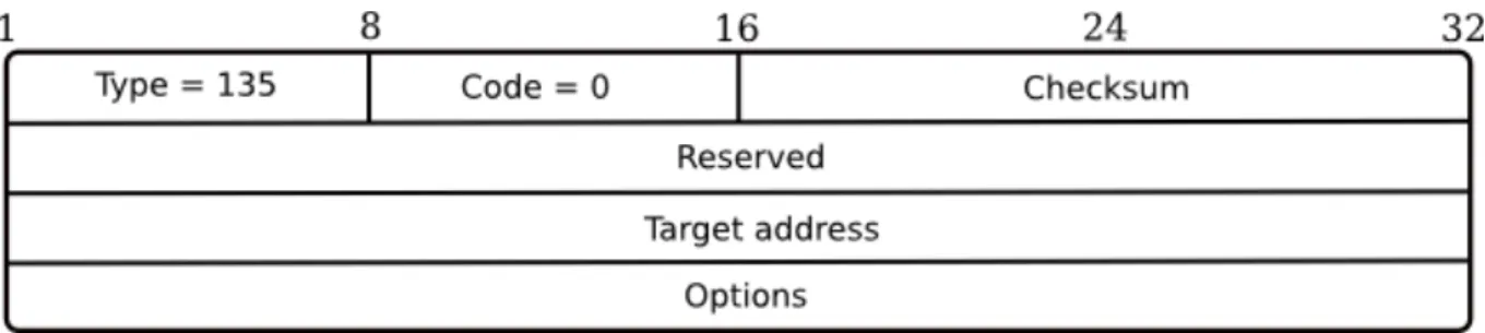
NS is a message used when attempting to collect information about neighbors in the same link. It can be multicasted or unicasted. Its structure is presented in Figure 1.3 and includes:
Figure 1.3: Neighbor solicitation message.
Target address contains the address of the target of the solicitation. 1.1.1.4 Neighbor advertisement (NA)
It is a message used to respond to a NS message or to propagate new information about the interface. It is presented in Figure 1.4.
R represents the router flag. If it is equal to one, the sender is a router.
S is the solicitation flag. A flag set to one means that the advertisement is sent in response to a NS.
O is the override flag. The advertisement overrides an existing cache entry and uploads the cached link layer address when this bit is set to one.
Figure 1.4: Neighbor advertissement message.
Target address is equal to the target address of the NS message if the bit S is set to one, else it will be equal to the local-link address of the sender.
1.1.1.5 Redirect
Router sends redirect message (Figure 1.5) to inform a host of a better first hop node.
Figure 1.5: Redirect message.
Target address is the link local address of the best first hop.
Destination address is the address of the destination to which the packet is redi-rected.
1.1.2
ND options
Options might complement previous messages. They all have the same TLV format (TLV for Type-Length-Value) and are defined in [5].
1.1.2.1 Source/Target link layer address
This option given in Figure 1.6 is composed of the following fields:
Type field is equal to one when the link-layer address used is the source one. Type field is equal to two when the link-layer address used is the destination one. Length field represents the length of the option in words of 64 bits.
1.1.2.2 Information about the prefix
This option contains the information needed during the configuration of the equipment.
Figure 1.7: Prefix option.
This option given in Figure 1.7 is composed of the following fields: Prefix length field contains the number of leading bits that are valid.
L is the on-link flag. When set to one, it means that this prefix can be used for on-link determination.
A is the autonomous address configuration flag. When set to one, it indicates that it could be used for stateless address autoconfiguration.
Valid lifetime contains the length of time in seconds that the prefix is valid for the purpose of on-link determination.
Preferred lifetime represents the period of time when the addresses generated from the prefix via stateless address autoconfiguration remain preferred.
Prefix contains the prefix itself. 1.1.2.3 Redirected header
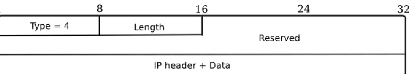
This option is used with the redirection message and contains all or parts of the packet that is being redirected. It is defined as presented in Figure 1.8.
Figure 1.8: Redirected header option.
IP header and data contain the original packet truncated to ensure that the size of the redirected message does not exceed the minimum MTU required to support IPv6 over the link.
1.1.2.4 MTU
The MTU option (Figure 1.9) is used in RA message to ensure that all nodes on a link use the same MTU value in case when the link MTU is not known.
Figure 1.9: MTU option.
1.1.3
ND applications
ND is a protocol used to organize the communication over a link in an IPv6 environment. The main functions of ND [5] are reviewed below.
1.1.3.1 Address resolution
This mechanism consists of sending a NS message whose destination is given by the solicited-node multicast address. The packet’s target address field contains the addresses of the neighbors to be solicited. The host responds with a NA, indicating its IPv6 address in the target address field and its physical address in the target link-layer address option. This process is done in IPv4 by the protocol ARP.
1.1.3.2 Host autoconfiguration
An interface can be conFigured manually by the network administrator, or configuration can be performed automatically. This latter possibility has become extremely important in IPv6 because of address length and the need to renumber sites more frequently. In IPv6, each address is associated with a period of validity so that network topology can be
changed automatically. To reduce the impact of renumbering on applications, two timers are used for each address. Initially, an address is classified as preferred, meaning that it can be used without restrictions as either a source or destination address. Once the preferred lifetime expires, the address goes to the deprecated state, i.e., the address is still valid but its use is discouraged for new communications. When the second timer, called the valid lifetime, expires, the address becomes invalid and can no longer be used. In this way, it is highly likely that the applications which use an address that has gone to the deprecated state will end before the address becomes invalid. There are two ways to address autoconfiguration:
The stateless autoconfiguration which is based on the creation of an interface iden-tifier by the host and then its verification by constructing the link-layer address related to this suffix and verifying it by using the duplication address detection which is explained after.
The stateful autoconfiguration uses a DHCP server to assign addresses to the inter-faces.
1.1.3.3 Duplicated Address Detection (DAD)
After a station gets a unicast address, it must check that it is unique before assigning it to the interface. To do so, the station sends a NS message in which the IPv6 header source address field is set to the unspecified address and the destination address field is set to the solicited-node multicast address. If the same unicast address has already been assigned to another node, the latter responds with a NA. When the node that initiated the DAD procedure receives this message, it disables the use of that address.
1.1.3.4 Neighbor Unreachability Detection (NUD)
This process gives a host the ability to test if a neighbor is still reachable or not. In fact, the host sends a NS to one of its neighbor and waits for NA. If no reply comes, it sends some other NS and in case of no response, it discards the entry related to that neighbor from its cache.
1.1.3.5 Router discovery
When a new node joins the link, it seeks for a new default router by sending a RS to the multicast address specific to routers and waits for an RA. If there is no response, the neighbor assumes that there is no router on the link.
1.1.4
ND attacks
In this section we study some of the attacks that have been discovered and have been identified as possible against ND. Those attacks are detailed in [1].
1.1.4.1 NS/NA spoofing
NS or NA spoofing basically involves the emission of faked NS or NA messages in order to modify the association between the L2 and L3 addresses of a victim’s peer in its cache. An attacker sends a NA or a NS with the target IP address as source address and a fake (or its own) link layer address, in the source link layer option, to a target peer which represents the victim. The latter updates its neighbor cache with the new information he gets. So that the attacker succeeds in spoofing the victim identity.
1.1.4.2 NUD failure
NUD is used to monitor the reachability of local destinations. In case node B left the network, and node A is sending some NUD NS message, an attacker can make a node A thinking B is still connected by sending to node A a NA using B address. So it spoofs the identity of B. In the case where B tries to join the network again, it will not be able to use its previous address and will be denied of service if it can not autoconFigure a new interface identifier.
1.1.4.3 DAD DoS attack
A new node (or a node that has changed its address) in a stateless address autoconfigu-ration performs DAD testing, and an attacker responds to all its NS messages. As such the host will never be able to get an address.
1.1.4.4 RS/RA DoS attacks
Many scenarios could be developed using RS/RA. Some of them are next described: An attacker tries to be selected by other nodes over the link as the default router.
In order to be chosen as last hop router, the attacker spoofs the legitimate default router and sends periodic RA with lifetime set to zero. Once accepted, the attacker sends Redirect message to hosts and disappears. That will cause a DoS attack. An attacker makes all nodes on the link think that they are all local by killing the
default router using a DoS attack or sending a spoofed RA with a lifetime equal to zero.
A malicious node sends RA advertising bad prefixes. The target uses one of those prefixes to build its own address, and launches successful DAD operation (No re-sponse to NS). The target will not be able to communicate over the network. An attacker designs parameters concerning the way of the autoconfiguration
(state-less or stateful) and sends them to the target which will use them to create its address but in fact it will be denied of service.
1.1.4.5 Replay attacks
All ND messages could be replayed. For example, an attacker could replay RA or Redirect messages of a router that retired from the link to make a DoS attack to all nodes connected. In fact, it can send a RA containing a list of fake prefixes that are no more valid and make the other nodes use them to create their addresses which will not be of a great usage. He could also replay NA to spoof the identity of a node.
1.2
Secure Neighbor Discovery (SEND)
SEND uses ND messages but has added new options and two new messages to secure the exchanges between routers and nodes and between nodes themselves.
We are going now to view the new messages introduced by this protocol and the options that it added, then we will discuss the ways SEND secures ND and at the end we will talk about possible attacks on SEND.
SEND messages and options are defined in [2].
1.2.1
SEND messages
SEND offers new functions such as Authorization Delegation Discovery (ADD) which is a mechanism based on the exchange of two new ICMPv6 messages to authenticate the router by the node before starting information exchange between the two entities.
ADD has been introduced because it was easy to conFigure rogue routers on an unse-cured link and it was difficult for a node to distinguish valid source of router information from invalid one. In fact a node needs this information before starting a communication with nodes outside the link. The objective is enabling the node to verify if the local router is true or false.
The two messages that have been introduced are Certification Path Solicitation (CPS) and Advertisement (CPA). In order to authenticate a router, the node sends a CPS (Figure 1.10) asking the router for a certification path to its trust anchor (which is an entity that the node trusts, that helps verifying the routers certificate, and that might be a certification authority). After receiving the CPS, the router generates a CPA (Figure
1.11) containing the certification path from the trust anchor to its own certificate so that certificate verification is made possible by the node itself.
Trust anchor gives also the router the permission to act as a router depending on its certificate.
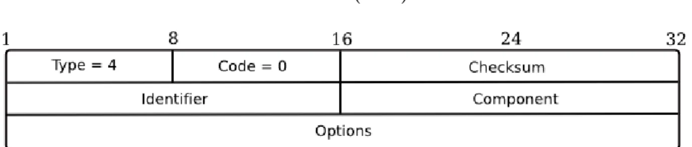
1.2.1.1 Certification Path Solicitation (CPS)
Figure 1.10: CPS message.
The identifier contains an unsigned integer that helps matching advertisements to solicitations.
The component field contains an unsigned integer referring to the component iden-tifier corresponding to the certificate that the receiver wants to retrieve.
1.2.1.2 Certification Path Advertisement (CPA)
Figure 1.11: CPA message.
The identifier contains the same value of the identifier field than the CPS message. All components field is used to inform the receiver of the number of certificates in
the entire path.
Component field is used to inform the receiver which certificate is being sent. The sending of path components should be ordered so that the certificate after the trust anchor is sent first. Each certificate sent after the first can be verified with the previously sent certificates. The certificate of the sender comes last. The trust anchor certificate should not be sent. A value of zero indicates that there are no more components coming in this advertisement.
1.2.2
SEND options
SEND has introduced six new options to secure SEND and ND messages exchanged between the hosts over a link.
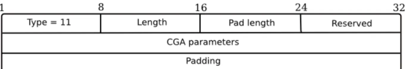
1.2.2.1 CGA option
CGA generation process will be studied in chapter 2. Here we only analyse the CGA option format presented in Figure 1.12.
Figure 1.12: CGA option.
The length contains the value of the option length in word of eight octets. The Pad length contains the number of padding octets.
CGA parameters are defined as in [3] and will be detailed in chapter 2.
Padding field contains bits that are set to zero and that must be ignored by the receiver.
This option must be present in all SEND messages (we do not consider the case where unspecified address is used; this case is discussed in [2]).
1.2.2.2 RSA signature option
This option carries the RSA signature of every ND message going to be sent. It has the following structure (Figure 1.13):
The key hash field contains the leftmost 128 bits of a SHA-1 hash of the public key used for constructing the signature. Its purpose is to associate the signature to a particular key known by the receiver (in our case it is the public key of the sender that will be verified using CGA verification described in chapter 2)
The digital signature is realised using RSA signature scheme and covers the following fields: the CGA type tag value for SEND (it will be explained in chapter 2), the source address from the IP header, the destination address of the receiver, the type; code and checksum fields of the ICMPv6 header, the ICMPv6 fields that come after the checksum and before the options, and the ND options preceding the RSA signature option.
This option must be present in all SEND messages (we do not consider the case where unspecified address is used; this case is discussed in [2]).
1.2.2.3 Timestamp option
The purpose of the Timestamp option (Figure 1.14) is to make sure that unsolicited advertisements and redirects have not been replayed. This option must be present in all SEND messages.
Figure 1.14: Timestamp option.
The timestamp field contains the value of the number of seconds since a specific date (January 1, 1970).
1.2.2.4 Nonce option
The purpose of the nonce option is to make sure that an advertisement is fresh and matches a solicitation sent by the node earlier. This option must be present in all solicitation messages. It has the following format (Figure 1.15):
Nonce is a field containing a random number selected by the sender of the solicitation message (at least six bytes).
1.2.2.5 Trust anchor option
This option is used only in CPS and CPA messages. It is presented in Figure 1.16.
Figure 1.16: Trust anchor option.
The name type contains the type of the name included in the name field. It can be: DER encoded X.501 name or fully qualified domain name (FQDN).
The pad length contains the number of padding octets. The name field the name identifying the trust anchor. The padding field bits that are set to zero.
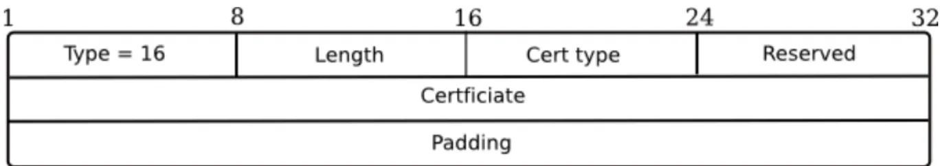
1.2.2.6 Certificate option
This option is used only in CPA messages and contains only one certificate. It is presented in Figure 1.17.
Figure 1.17: Certificate option.
The cert type field contains the type of the certificate included in the certificate field.
1.2.3
SEND usage
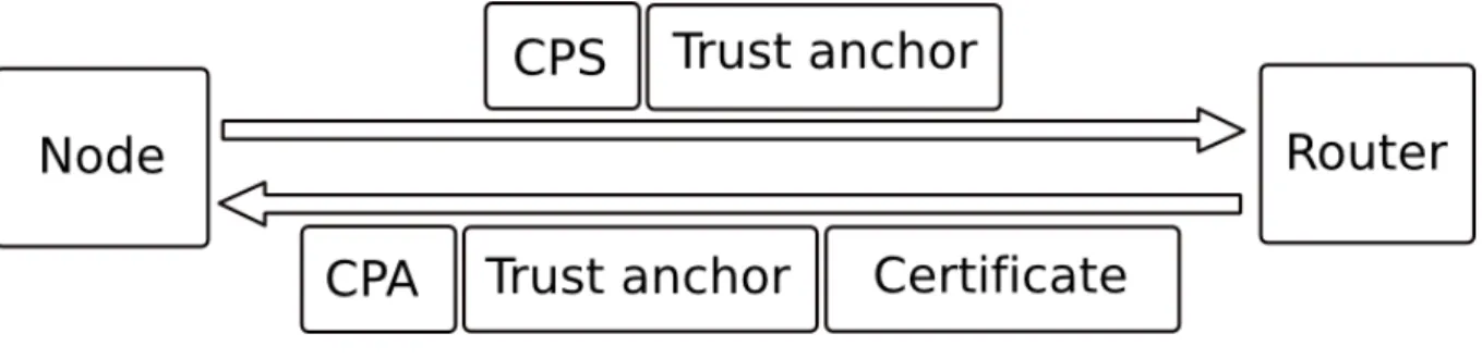
When a new node joins a network, it starts by sending a RS message to get information about the possible prefixes that it can use to generate its CGA. When it receives a response from a router, it can not be sure about its identity and the validity of its prefixes. So in order to authenticate the router, the node sends him a CPS message (Figure 1.18) including the name of a trust anchor (known and trusted by the sender) using a trust anchor option. So the router responds with a CPA message containing a list of certificates matching its certificate to the trust anchor’ s one.
Figure 1.18: CPS/CPA messages.
After authenticating the router via its certificate, the node uses one of its prefix with some parameters to compute its CGA and to form the corresponding CGA parameters structure. The node is now able to communicate with its neighbors using SEND messages.
Two situations are possible:
When the node sends a solicitation message (NS or RS), it has to include the fol-lowing options: CGA parameters option, RSA-signature option, timestamp option and nonce option. The use of nonce is mandatory in this case because the message sent is a solicitation. The corresponding response (advertisement) has to contain the same nonce value in order to create a binding with the solicitation (Figure 1.19).
Figure 1.19: SEND options usage.
When a node or a router sends an advertisement without being solicitated, it does not need to include a nonce. This may happen when a node changes one of its addresses (physical or CGA(IPv6 address)) or when a router wants to multicast new information about its prefixes.
1.2.4
SEND securing ND
In this section, we study how SEND secures ND against the attacks that have been detailed in the first section of this report.
1.2.4.1 NS/NA spoofing
The threat here is that a spoofed message may cause a false entry in a node’s Neighbor Cache. This attack is countered thanks to the use of CGA option and RSA signature option. NS or NA messages will have to be signed to make an entry in the cache. So a node receiving a NS or NA message has to verify the identity of the sender thanks to the signature in order to update its cache. An attacker will have to realize a collision with the CGA to get a valid private key which makes him able to sign the fake NS or NA that he creates.
1.2.4.2 NUD failure
Thanks to the use of the CGA and RSA signature options, a proof of authorization to use the interface identifier of the address being solicitated is given. So only the address owner is able to responds to the NUD probes.
An attacker will not be able to spoof the identity of the leaving node because it will have to respond to NS using a message signed by the target private key which it does not have.
1.2.4.3 DAD DoS attack
In the DAD mechanism, the NA message in response to a NS message mechanism must include RSA signature option as proof of identity. The attacker will not be able to respond to a NS message because it does not possess the private key needed to generate the RSA signature.
1.2.4.4 RS/RA attacks
To counter those attacks, a router will only have to add RSA signature option to the RA message. So nodes will have to accept only signed messages coming from a router. In this case, a malicious node which wants to execute those attacks will have to get the router’s private key to be able to sign its self generated RA messages.
1.2.4.5 Replay attacks
In order to counter the replay attacks, SEND introduced two options which are the times-tamp for the unsolicited advertisements and nonce for solicited advertisements in order to create a challenge response protocol (concerning the nonce option).
Conclusion
In this first chapter, we have introduced the context in which CGA has been developed. In the sequel, we are going to study in details the CGA generation process, the different modifications that have been supposed to be added to CGA and its different usages.
CGA generation, verification and
structure
Introduction
In order to introduce a new mechanism to decentralize the association between a public key and its owner, CGAs have been introduced.
The older techniques used were all centralized with a unique entity generating certifi-cates binding hosts to their public keys. The certificertifi-cates generation entity is called the certification authority.
CGAs are IPv6 addresses where the interface identifier contains information about the public key of the host owning the address.
In this chapter we introduce the algorithms used for CGA generation, verification and the structure used to create these addresses. Then we describe the possibility of introducing some modifications in the generation process.
2.1
CGA presentation
CGAs were initially developed to be used with the SEND protocol [2]. They were used to secure neighbor discovery messages exchange [5].
Before the generation of a CGA, the host must choose a three bits length security value SEC which is used to make brute force attack against CGA generation algorithm very difficult.
Every host in a network can generate its own CGA based on two SHA-1 hashes calculus over a structure called the CGA parameter structure. The 64 leftmost bits of the first hash (hash1) are used as interface identifier with no regard to the three first bits (if we are counting from the left to the right), which correspond to the SEC value, and to seventh and eightieth bits which are the universal and group flags of an IPv6 interface identifier
(known as the u and g bits in the standard IPv6 address architecture format of interface identifiers defined in [9]). The 112 leftmost bits of the second hash value (hash2) are used
Figure 2.1: A Cryptographically Generated Address.
with SEC value to increase the complexity of CGA generation. To validate a generated address, we must verify that 16*SEC leftmost bits of hash2 are equal to zero (for example if SEC = 2, we will have to verify that 32 leftmost bits of hash2 are equal to 0, else we will have to recompute the address).
Now, we are going to study the CGA parameters structure.
2.2
CGA parameters structure
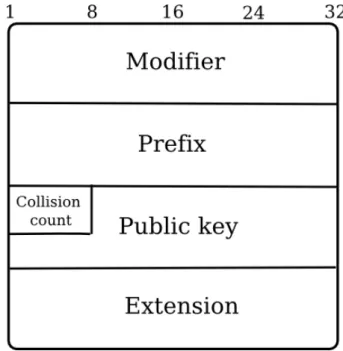
CGA parameters structure has the format giving in Figure 2.2:
Figure 2.2: CGA parameters structure.
Modifier contains a 128 bits random value. It is used during CGA generation to implement hash extension and to enhance privacy by adding randomness to the address.
Public key field contains the public key of the host which is DER encoded. It should have at least a length of 384 bits. Actually the only key used in SEND is generated using RSA1.
The extension field is an optional field.
2.3
CGA generation
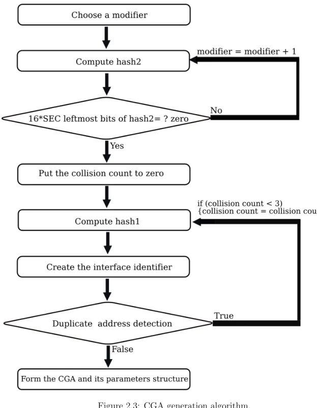
The CGA generation process takes as input three parameters: the public key of the host (DER encoded), the prefix of the address and the security parameter SEC. To generate a CGA, the following steps must be followed (see Figure 2.2):
1. Choose a random modifier.
2. Compute hash2 using as input to the SHA-1 function the following elements concate-nated respectively from the left to the right: the modifier, nine bytes of zero (prefix field and collision count are taken equal to zero), the public key (DER encoded), and extensions. (We take only the 112 leftmost bits to form hash2)
3. Compare the 16*SEC leftmost bits of hash2 to zero: if they are all equal to zero then go to the next step, else increment the modifier value by one and go back to step 2.
4. Set the collision count to zero.
5. Compute hash1 using as input to the SHA-1 function the following elements: the final value of the modifier, the prefix, the collision count, the encoded public key and all extensions. (We take only the 64 leftmost bits to form hash1)
6. Form an interface identifier using hash1 by replacing the three leftmost bits by SEC value and by setting the u and g bits to zero (those bits are equal to the seventh and eightieth bits if we start counting from the left).
7. Form an IPv6 address using the prefix (that was provided as input) and the calcu-lated interface identifier.
8. Perform duplicate address detection (defined in chapter 1 and [5]), if a collision is detected, increment the collision count by one and go to step 5.
9. Form the CGA parameter structure as it was defined in section 1.2.
To make it possible for mobile nodes whose subnet prefixes change frequently to use SEC values greater than zero, it has been decided not to include the subnet prefix in the input of Hash2.
The collision count must not have a value greater than two. First, it is unlikely that three collisions would occur and this precludes any DoS attack. Second, an attacker searching to match a given CGA interface identifier with its own public key can try all different values of a collision count without repeating the brute force search for the modifier value.
2.4
CGA verification
When receiving a CGA address with its structure, the host can verify the address by executing the following process but he will not be able to detect if the packet containing the address is being replayed and will not also authenticate the sender unless the packet is signed. The following steps must be performed to check the validity of the address (see also Figure 2.3):
1. Check that the collision count is equal to 0, 1 or 2.
2. Check that the subnet prefix of the address is equal to the prefix value of the CGA structure.
3. Compute hash1 by applying SHA-1 to the CGA parameters structure.
4. Compare hash1 to the interface identifier of the address while ignoring the three first bits corresponding to SEC value and the bits corresponding to u and g.
5. Get the SEC value by taking the three leftmost bits of the interface identifier.
6. Compute hash2 by applying the SHA-1 algorithm to the CGA structure containing: the modifier, nine bytes of zero, the public key and all extensions.
7. Compare 16*SEC leftmost bits of hash2 with zero.
If the verification fails at any step, the execution of the algorithm must be stopped. Else, the verifier will have verified the address and the public key of the sender.
2.5
CGA signature
When a host wants to sign a message, he needs his private key (generated using RSA), his CGA, the corresponding CGA parameter structure and must also have a 128 bits type tag (which is a randomly chosen value, which prevents accidental type collisions with other protocols). First, it concatenates the type tag value with the message to sign (respectively from the left to the right) to form a new message which will be used next as input to the
2 signature algorithm (actually it is the only kind of signature used). Finally, it sends the
message, its signature and also the CGA parameter structure.
The node that receives the previous data will have to verify the signature. So it starts by verifying the CGA using the algorithm presented in section 1.4. Then, it concatenates the message received with the type tag to form the new message which is used as input to the digest computation and finally it executes the RSA signature verification algorithm.
Figure 2.4: CGA verification algorithm.
The verifier must accept the signature as valid if only both the CGA verification and the signature verification succeed.
When a node transmits a message and its signature, it does not send the type tag value because it must be known by all the nodes belonging to the same network. The only type tag used actually is the SEND one.
2.6
Support for multiple hash algorithm in CGA
The hash function used when generating a CGA is SHA-1. RFC 4270 [10] presents some successful attacks against hash function. For instance, it has been verified that the property of collision free of some hash algorithms is no more reliable. It means that an attacker can find two messages that produce the same hash. So the non repudiation of a signed message is no more trustworthy.
As CGA uses the SHA-1 only to create the interface identifier, the previous kind of attacks is not feasible. “Essentially, all the current applications of CGA rely on CGA to
protect a communication between two peers from third party attacks and not to provide protection from the peer itself”[11] so there is no need to provide non repudiation property. The need to enable multiple hash function support in CGA is motivated by the un-known needs of future CGA applications which may become susceptible to attacks against the collision free property of SHA-1. In addition, present attacks against hash functions encourage providing the possibility of using new powerful hash function. When speaking about implementing new hash algorithm with CGA, we must answer the following ques-tion: where to encode the hash function being used? Here are some proposals of encoding hash functions:
The first idea that comes in mind is to include a new Type-Length-Value (TLV) extension to the CGA parameters structure. This hash algorithm extension contains the hash algorithm used. This kind of extension makes CGA susceptible to the downgrading or bidding down attacks. In the bidding down attack, the attacker generates the same target CGA using a weak hashing algorithm having as input the CGA parameters structure (belonging to the target) and the corresponding hash algorithm extension. Even if the target generated its address using a strong hash algorithm. A way to counter this attack is to encode the CGA hash function identifier in the address itself.
Figure 2.5: Bidding down attack.
The second approach consists in using some bits of the interface identifier to encode the hash algorithm version. This method is rejected because it weakens the CGA generation as less hash information can be encoded in the interface identifier. The most interesting approach consists in using the security parameter SEC [11]
force attack and hash function identifier. SEC is used to express the need of using a new hash function and to fix the amount of bits of hash2 that must be equal to zero (16*SEC leftmost bits of hash2 must be equal to zero). If the number of hash functions increases, some SEC values will be reused (for example the SEC values corresponding to the weakest hash functions). In any case, an implementation must not simultaneously support two different meanings of SEC.
2.7
CGA and DHCP
CGA is created by a node using its public key and some parameters. It is a kind of stateless address autoconfiguration. Its generation algorithm is complex and includes some operations which are specially added to increase the cost of brute force attack against this type of address.
In a CGA parameters structure, the modifier is a 128 bits random integer whose computing operation consumes many resources. It also depends on the security parameter SEC which is going to be used during the CGA generation.
The SEC value is chosen by the administrator of the network depending on the infras-tructure and the level of security needed. Greater is SEC, more efficient is the provided security, but also greater is the time and power consumption for the generation algorithm. This generation function is too much consuming for mobile nodes having restricted com-putational capacities and power. To overcome this problem, one proposed solution is to delegate the computation of the modifier to a server which could be a DHCP server.
Using a server offers some new features such as asking nodes generating their own addresses to register. So nodes belonging to the same network are authenticated. In mobile networks where proxying is needed, a server can be used to notify end hosts about the proxying of their SEND messages. The server informs the proxy about the different CGA created and their corresponding parameters structure so it uses its private key to sign messages coming from those addresses.
In this section, we present a proposal that is based on a DHCP server helping nodes to generate CGA and providing a centralised administration [12] [13].
DHCP server can be used to:
Inform nodes about the parameters used to conFigure a CGA (see Figure 2.6). Compute the modifier so the node will not have to do the exhaustive calculus. The
server can compute the modifier or redirect the CGA parameters to another host which will do the computation. Next, the server can generate the CGA and send it to the requesting node (see Figure 2.6).
Figure 2.6: DHCP server sending CGA parameters.
Figure 2.7: Modifier computation by the DHCP server.
Figure 2.8: Generated address registration in the DHCP server.
Forward proxying information.
There are some threats that appear due to the fact of using DHCP with CGA, we can list for example:
A malicious node propagates in DHCP message a SEC value providing less security than it would be desired by the network administrator.
A malicious node overloads the server with a number of requests for generating modifiers with different values of SEC trying to cause denial of service especially with the SEC greatest values (7 and 6). This attack is very difficult to realise thanks to the limited number of SEC values (8).
An attacker (spoofing a DHCP server) requests from a node to generate different modifiers (when they are generated locally) using different requests containing di-verse SEC values. The attacker aim is to cause a denial of service.
A malicious node generates fake messages carrying fake information to exhaust proxy resources.
An attacker overloads the DHCP server with address registration requests until causing denial of service.
Conclusion
In this chapter, we have seen how to generate a CGA and how to verify it. We have also explained the possible extension that has been proposed to enhance the possibility of using another hash function than SHA-1 during CGA generation. Concerning the use of a DHCP server to help nodes acquiring a CGA, it still only a proposal but it could become a reality especialy in networks using CGA with power and computational limited devices.
CGA usage in multihoming and
mobile networks
Introduction
Initially CGA was introduced to be used with SEND in order to secure ND. Actually CGAs are being adapted for usage in mobile networks where ND proxying is needed and in multihomed networks where a node can be connected to many internet service providers (ISP) at the same time.
In this chapter, we first introduce how CGA was adapted to be used in multihomed networks with Hash Based Addresses (HBA) [14]. Next we present the different solutions proposed to enable secure ND proxying.
3.1
CGA and HBA usage in multihoming networks
In this section we describe HBA and how to use them with CGA.
3.1.1
HBA presentation
The concept of HBA has been introduced specially for nodes belonging to multiple net-works at the same time. In this case, a node has multiple addresses with multiple prefixes. The threats that affect multihoming networks are basically redirection attacks which could be divided into two groups: hijacking attacks that consist on stealing ongoing or future communications from a victim and flooding attacks.
To counter these threats, we use HBA with the protocol SHIM6 [15].
The SHIM6 is a layer 3 approach and protocol for providing locator agility below the transport protocols so that multihoming can be provided with failover and load sharing properties. It introduces a new approach to associate locator as upper-layer identifiers. In fact, the identifiers name space corresponds to the locator selected in the initial contact
with the remote peer as the upper layer identifier (ULID). Even if it happens that the locator changes due to a failure, the upper protocol stack elements will continue to use this upper level identifier without changes.
SHIM6 is used by a host which has multiple IPv6 addresses to setup state with other hosts. This state can be used later to failover to a different locator pair. This protocol allows existing communications to continue when a site that has multiple connections to the internet experiences an outage on a subnet.
HBA binds together multiple IPv6 addresses that belong to the same node. It contains information about the different prefixes. The technique used consists on including a hash of the permitted prefixes in the low order bits of the IPv6 address. Its motivation is to provide a mapping between the ULID and the different locators.
For example, we consider a node having three ISP. It will have three addresses having three different prefixes: A, B and C. To create the different HBAs the following actions have to be executed:
1. Create a list of prefixes: L = A, B, C
2. Choose a random value called modifier.
3. Compute the interface identifier for every prefix from a hash value having as input: the value of the modifier, the prefix and L.
4. Create the IPv6 addresses as presented in Figure 3.1.
Figure 3.1: Example of three HBA.
In next sections, we detail HBA generation algorithm and then expose a solution using HBA and CGA together.
3.1.2
HBA generation algorithm
When generating a HBA these steps could be followed (this algorithm has been defined in [16] and it is used to generate only one HBA):
1. Choose a security value SEC.
2. Compute C = SHA-1 (hba k SEC k Subnet Prefix k Modifier k P1 k . . . k PN), hba
3. Compute G = 64 + 20 * SEC rightmost bits of C, if the 20 * SEC leftmost bits of G are zero, go to the following step. Else, compute a new modifier and go to step 2.
4. Create the interface identifier by taking the rightmost 64 bits of C and putting the u and g bits to one and the bits 63 and 64 to SEC value.
5. Create the IPv6 address: @ = Subnet Prefix k interface identifier.
In a multihoming network the parameters (P1 . . . PN) are remplaced by the prefixes of
different ISPs.
3.1.3
HBA/CGA compatibility
The HBA technique uses the interface identifier of an IPv6 address to encode information about the multiple prefixes used by a multihomed host but it does not contain crypto-graphic information like CGA.
There are at least two reasons to provide HBA/CGA compatibility:
1. If HBAs are not compatible with CGAs, multihoming node will not be able to do secure neighbor discovery using SEND. HBA provides only fault tolerance (using SHIM6) but it does not provide security (using SEND).
2. CGA provides additional features that can not be achieved using HBA only: it is impossible to add new prefixes to the original set of prefixes after generating the set. So the new prefix will not be available for established communications and only new ones benefit from it.
The algorithm of HBA/CGA generation has as input the public key of the generating node and the list of prefixes belonging to different ISPs. The node using HBA/CGA tells its peers to use HBA verification when one of the addresses of its HBA/CGA set is used as locator or to use CGA verification when a new address that does not belong to the HBA/CGA set is used as locator.
The parameter introduced to bind HBA and CGA is a multi-prefix extension for CGA parameters structure.
The HBA set will be identified by a CGA parameter data structure that contains a multi-prefix extension.
Generation of a HBA is like using the CGA parameters structure but with a random number replacing the public key.
The multi-prefix extension has a TLV format (Type-Length-Value) and has the struc-ture presented in Figure 3.2.
The P bit is used in the extension to indicate whether a public key is used or not in the HBA/CGA parameters structure.
Figure 3.2: Multi-prefix extension for CGA parameters structure.
3.1.4
HBA/CGA generation algorithm
This algorithm is taken from the CGA generation process but it has been modified to enhance the possibility of creating many CGAs using the multi-prefix extension. It takes as input: the nodes public key, a vector of n 64 bits prefixes and a SEC value. It has the following steps (see Figure 3.3):
1. Generate the multi-prefixes extension and the vector of n 64 bits prefixes. If a public key is given then the P flag is set to one.
2. Choose a random modifier.
3. Compute hash2 using as input to the SHA-1 function the following elements con-catenated respectively from the left to the right: the modifier, nine bytes of zero (prefix field and collision count set to zero), the public key (DER encoded), and extensions. (We take only the 112 leftmost bits to form hash2)
4. Compare the 16*SEC leftmost bits of hash2 to zero: if they are all equal to zero then go to the next step, else increment the modifier value by one and go back to step 3.
5. Set the collision count to zero.
6. For i from 1 to n (number of prefixes) do
(a) Compute hash1[i] using as input to the SHA-1 function the following elements: the final value of the modifier, the prefix[i], the collision count, the encoded public key and the extension. (We take only the 64 leftmost bits to form hash1) (b) Form an interface identifier using hash1[i] by replacing the three leftmost bits by SEC value and by setting the u and g bits to zero (those bits are equal to the seventh and eightieth bits if we start counting from the left).
(c) Form an IPv6 address using the prefix[i] (that was provided as input) and the calculated interface identifier.
(d) Perform duplicate address detection, if a collision is detected, increment the collision count by one and go to step 6.
(e) Form the CGA parameter structure using: the final value of the modifier, the prefix[i], the final value of the collision count, the public key and the multi-prefixes extension.
Figure 3.3: HBA/CGA generation algorithm.
3.1.5
HBA/CGA verification
To verify a HBA based on CGA, we must start by executing the verification process presented in section 2.4. This verification aims to prove the binding existing between the address and the corresponding CGA parameters structure. Such verification is useful when the goal is creating a binding between the public and the HBA.
Next, we have to verify that the HBA belongs to a HBA set associated to a given CGA parameters data structure. A HBA set is identified by a CGA parameter data structure that contains a multi-prefix extension.
To verify that a HBA(1) belongs to a HBA set associated with another HBA(2), we verify that the HBA(1) prefix is included in the prefix set defined in the multi-prefix extension, then we substitute the prefix included in the subnet prefix field (of the CGA parameters structure associated to HBA(2)) by the prefix of the HBA(1) and we perform the CGA verification process defined in section 2.4.
The inputs to the HBA verification process are a HBA and a CGA parameters struc-ture. It is described by the following steps and Figure 3.4:
1. Verify that the HBA prefix is included in the prefix set defined by the multi-prefix extension.
2. Run the CGA verification process described in section 1.4 after changing the subnet prefix field with the prefix of the address being approved.
Figure 3.4: HBA/CGA verification algorithm.
3.2
CGA and ND proxying
In IPv6 mobile environment [17], it is necessary to provide ND proxying. The proxy known as Home Agent performs address defence which consists in protecting the mobile nodes address when it leaves the home link. This allows other nodes belonging to the same link to continue sending traffic to the node. It also prevents any new arriving node from claiming the mobile nodes address [18].
The ND proxy is responsible for answering NS that are addressed to a mobile node which left the link. The proxy answers using a NA message whose target address field contains the mobile node’s address. However the IPv6 address and the link layer address correspond to the proxy’s ones.
In this section, we take a look at neighbor discovery (ND) proxying [19]. We explain why it is not possible to use SEND to secure ND proxying. At the end, we discuss the proposed solution for securing ND.
3.2.1
Proxy behaviour
When a proxy receives an IPv6 packet, it updates its interface cache by adding an entry for the sender. The way it proceeds this packet depends on its type. It focuses on if it
negotiates link layer address or not, because only packets carrying information about link layer addresses are going to be proxied such as neighbor solicitation message packets.
When a proxy receives multicast packets on one of its interface, it forwards it un-changed on all other proxy interfaces on the same link. When it receives ordinary unicast packet, it forwards it to its interface for which the next hop address appears in the neigh-bor cache (if it is not locally destined).
The link layer header and the link layer address within the payload for each forwarded packet will be modified as follows:
The source address will be the address of the outgoing interface.
The destination address will be the address in the neighbor entry corresponding to the destination IPv6 address.
“The link layer address within the payload is substituted with the address of the outgoing interface [19]”.
3.2.2
ND proxying
Two scenarios exist for ND proxying as described below.
3.2.2.1 IPv6 mobile nodes and ND proxy
A proxy has to deliver packets to a node whether it is present or not in the home network. In mobile IPv6 network, the proxy corresponds to the home agent. It answers to NS destinated to a node which left the link. It responds using a NA message whose target address field contains the mobile node address but the IPv6 address and the link layer address correspond to the proxy ones(see the example in the Figure 3.5).
In this case, no solicitations are proxied because the proxy generates the advertisement itself. The proxy needs to override existing valid nodes cache entries (which could be protected by SEND) when a host leaves its home network. Next, it uses its link layer address to redirect the flow of packets in the tunnel connecting the home agent/proxy to the mobile node.
3.2.2.2 Bridge like ND proxies
In this case, the proxy takes place between two segments, it forwards messages while mod-ifying their source and destination MAC addresses and rewrites their link layer address options and override flags.
The bridge like ND proxying (Figures 3.6 and 3.7) has been defined in [20]. It allows also router discovery operation based on the exchange of a RS and RA messages.
Figure 3.5: Example of ND proxying in mobile IPv6.
Figure 3.6: Example of bridge like ND: NS/NA messages.
3.2.3
Securing ND proxying
All proxied messages presented previously are not secured because they are based on the ND protocol which is itself insecure. So all attacks against ND are still feasible against proxied ND. In addition, some malicious nodes can spoof the proxy identity and cause denial of service attacks. For instance, an attacker which executes spoofing will not forward the messages which the proxy is supposed to forward causing unreachability between the communicating nodes.
One approach consists on using SEND messages to secure proxied ND but this can not be done without changing SEND or the proxying procedure. In fact, a proxy has not the public and private key pair used to generate the mobile node address and to sign different SEND messages. So the fact of rewriting the message (which is going to be forwarded) breaks the digital signature of the generating node.
Figure 3.7: Example of bridge like ND: RS/RA messages.
In the next sections, we discuss two proposals to secure neighbor discovery proxying based on CGA.
3.2.3.1 Multi-key CGA
We have seen previously the two major ways of proxying:
Proxying of a mobile node s home address by its home agent: in this case the mobile generates a certificate authorizing the home agent to proxy the address.
Proxying by a bridge approach: in this case the proxy obtains a certificate from the router authorizing it to proxy.
The problem with these methods is that a querying node can discover from the cer-tificate and its parameters whether the message is generated by a proxy or by the node itself. An attacker could find out whether or not the owner of the address was on its home link. So it can try to spoof the address while its owner is off link.
The idea proposed to provide anonymity of the signer consists in modifying SEND signature option. A signer has to use a kind of signature which will not permit the signature verifier to determinate who signed the message but it will be able only to verify the validity of the signature. The used signature scheme is called ring signature1 [21].
In a ring signature scheme, the signer uses its own private key and the public keys of a possible group of signers that it chooses randomly (even without their agreement). The ring signature is signer-ambiguous which means that the verifier should be unable to determine the identity of the actual signer in a ring of size r with a probability greater than 1/r[21].
Using this kind of signature permits a mobile node to use its own private key and a proxy public key to sign all its proxied messages. An attacker will not be able to determi-nate who signed the message and consequently the state of the mobile node which he is targeting. The node uses in that case an RST (Rivest-Shamir-Truman) ring signature[21] option instead of a standard SEND RSA signature option. In addition, it will add an RST signature suboption in the CGA parameters option. So the CGA parameters option will contain the public key of the node and the public key of the proxying router in the RST signature suboption. It generates a new kind of CGA called Multi-key CGA2 [18].
The multi-key CGA generation algorithm has the same steps than the CGA generation algorithm but it includes only one change in step 2 concerning the hash2 defined in chapter 2 section 2.3. Hash2 is computed using an SHA-1 hash over the structure formed by: the modifier, 9 bytes of zeros, a hash value having as input the nodes and routers public keys instead of the DER-encoded nodes public key and some extensions (if any).
The verification algorithm also includes one modification concerning the step 6 of the CGA verification algorithm defined in section 2.4 of the previous chapter. This change is related to hash2 computation and verification.
Before the CGA or signature verification, the verifying node must check that the routers public key in the CGA parameter option matches a certified public key from a router on the link. This ensures that the two keys used belong to two legitimate members of the group.
3.2.3.2 Authority delegation approach
Proxy neighbor discovery requires a delegation of authority on behalf of the absent address owner to the proxy. Without this authority, other devices on the link have no reason to trust an advertiser [20].
Authority delegation can be provided using two ways. First, routers that are certified by the routing authority using SEND can be also authorized and certified to proxy traffic for absent node on the link. Second, node which has CGA can sign the proxys public key and address so that it can be trusted. The certificate signed by the proxying node is passed to the proxy to use it as a proof of trust. It can be sent when sending the binding update message to the proxy (this message is used to indicate to the home agent that the node is absent). “In both methods, the original address owner’s advertisements need to override the proxy if it suddenly returns, and therefore timing and replay protection from such messages need to be carefully considered [20]”.
Conclusion
In this chapter we have seen the two other possible usages of CGA in addition to its usage with SEND. In the following chapters we are going to study the performance of CGA based on its CPU consumption and robustness. We will also introduce a new improvement to CGA to make its generation faster.