ÉCOLE DE TECHNOLOGIE SUPÉRIEURE UNIVERSITÉ DU QUÉBEC
MANUSCRIPT-BASED THESIS PRESENTED TO ÉCOLE DE TECHNOLOGIE SUPÉRIEURE
IN PARTIAL FULFILLEMENT OF THE REQUIREMENTS FOR THE DEGREE OF DOCTOR OF PHILOSOPHY
Ph. D.
BY
Amir Masoud TAHVILIAN
NUMERICAL AND EXPERIMENTAL STUDY OF A FLEXIBLE ROBOTIC GRINDING PROCESS
MONTRÉAL, JANUARY 20, 2015
This Creative Commons license allows readers to download this work and share it with others as long as the author is credited. The content of this work may not be modified in any way or used commercially.
BOARD OF EXAMINERS (THESIS PH.D.) THIS THESIS HAS BEEN EVALUATED
BY THE FOLLOWING BOARD OF EXAMINERS
Prof. Zhaoheng Liu, Thesis Supervisor
Department of Mechanical Engineering at École de technologie supérieure
Prof. Henri Champliaud, Thesis Co-supervisor
Department of Mechanical Engineering at École de technologie supérieure
Prof. Marie-José Nollet, Chair, Board of Examiners
Department of Construction Engineering at École de technologie supérieure
Prof. Stéphane Hallé, Member of the jury
Department of Mechanical Engineering at École de technologie supérieure
Dr Bin Shi, Independent External Evaluator
Aerospace Manufacturing Technologies Centre, National Research Council Canada
THIS THESIS WAS PRENSENTED AND DEFENDED
IN THE PRESENCE OF A BOARD OF EXAMINERS AND THE PUBLIC DECEMBER 12, 2014
ACKNOWLEDGMENTS
First of all, I would like to thanks my parents, Ahmad and Tahereh, my brother Amir for all the support, you provided for me during this stage of my life. This was simply not possible without your encouragement and unconditional love.
I sincerely thank my directors at École de Technologie Supérieure, Professor Zhaoheng Liu and Professor Henri Champliaud for their supervision and support during this research work. Their invaluable scientific advice and friendly attitude helped me to overcome all the difficulties through the period of my PhD study.
I would like to thank to Mr. Bruce Hazel, my supervisor at Hydro-Québec research institute (IREQ), whose grateful support, inspiring ideas and insightful discussions helped me for completion of my PhD program. I am also grateful for all the technical help and support from the SCOMPI team at IREQ during the experimental set-up preparation. A special thanks to Mr. Marin Lagacé for providing his image processing software and adding features specifically for this research purpose.
I also would like to thank the jury members who evaluated my thesis and for their constructive suggestions and helpful advice.
Finally, I acknowledge the financial support from Natural Science and Engineering Research Council of Canada (NSERC) and Hydro-Québec research institute (IREQ).
NUMERICAL AND EXPERIMENTAL STUDY OF A FLEXIBLE ROBOTIC GRINDING PROCESS
Amir Masoud TAHVILIAN SUMMARY
Robotic grinding is among the least studied processes due to its complexity compared to conventional grinding and other machining processes. In robotic grinding with a light, flexible robot, low manipulator stiffness is a key factor affecting process behavior and causing impact phenomena. Force prediction and thermal damage are important aspects to consider in robotic grinding because of the vibrational nature of the process. The portable robot used in the process under study is a multi-purpose track-based manipulator developed by IREQ, Hydro-Quebec’s research institute. The main application of this light-weight robot, named “SCOMPI” (Super COMPact robot Ireq), is in situ maintenance of hydro turbine runners. It is observed that the grinding process by this robot is interrupted at each revolution of the wheel rather than having a continous cutting action. This impact cutting behavior appears due to the low stiffness of the flexible manupulator under high grinding forces. Special attention has thus been given to gain a better understanding of the material removal process in such robotic grinding. The objective is to establish appropriate relations among chip formation, operational cutting forces, temperature, material removal rate and consumed power in the process.
The purpose of this study is to use numerical and experimental methods to gain a better understanding of this flexible robotic grinding process. First, a finite element thermal analysis is carried out to evaluate thermal aspects of the process, such as the energy partition ratio and temperature distribution in the workpiece. A new representation of the heat source in line with the impacting effects of robotic grinding is considered in the model. Experimental measurements in conjunction with numerical analyses led to an energy partition model applicable to this study under varying operating conditions. In the second part, the topography of grinding wheels used in the process is characterized and related to depth of cut. The cutting edges of wheels have a significant effect in process efficiency and are essential in understanding material removal in the grinding process. The variation of wheel topography due to process conditions is demonstrated. Knowledge of the edges involved in cutting during the process are vital for micro-scale modeling of cutting interactions occuring in the wheel-workpiece contact zone. Ongoing work on micro-scale force modeling through FEM will benefit from this wheel topography study. The third part of this thesis is dedicated to enhancing the empirical basis for an existing force model of the process. An impact cutting regime is observed by means of high-speed camera recordings and measured process force signals. This regime is detected at different grinding power levels and used in identifying the empirical coefficients. The energy partition model from the first part of study is also incorporated to obtain a friction-chip energy ratio used to determine the force model constants.
VIII
Keywords: robotic grinding; finite element analysis; thermal model, force model, impact cutting, wheel topography
IX
ÉTUDE NUMÉRIQUE ET EXPÉRIMENTALE D’UN PROCÉDÉ ROBOTISÉ DE MEULAGE PAR ROBOTS FLEXIBLES
Amir Masoud TAHVILIAN RÉSUMÉ
Le meulage robotisé est parmi les procédés les moins étudiés en raison de sa complexité par rapport au meulage traditionnel et à d'autres procédés d'usinage. Dans un procédé de meulage robotisé, la faible rigidité du manipulateur est un facteur majeur qui modifie le comportement du procédé et provoque des phénomènes d'impact. La prédiction de force et l’étude des dommages thermiques constituent ainsi des éléments importants dans l’étude du meulage robotisé afin de prendre en considération la nature vibratoire du procédé. Le robot portable utilisé dans le procédé à l'étude est un manipulateur sur rail à usage multiple développé par l'IREQ, l'Institut de recherche d'Hydro-Québec. La principale application de ce robot léger, nommé "SCOMPI", consiste en la maintenance sur place des roues de turbines hydroélectriques. Il a été constaté que le procédé de meulage avec ce robot n’est pas une action de coupe continue mais plutôt interrompue à chaque révolution de la meule. Ce comportement de coupe par impact apparaît en raison de la faible rigidité du manipulateur flexible soumis à des forces importantes de meulage. Par conséquent, une analyse détaillée a permis d’acquérir une meilleure compréhension du mécanisme d'enlèvement de matière lors du meulage robotisé. L'objectif de cette étude est donc d'établir des relations appropriées entre la formation des copeaux, les forces de coupe opérationnelles, la température, le taux d'enlèvement de matière et l'énergie consommée dans le procédé.
Cette étude vise aussi à utiliser des méthodes numériques et expérimentales dans le but d’acquérir une meilleure compréhension du procédé de meulage robotisé par robots flexibles. Tout d'abord, une analyse thermique par éléments finis est effectuée afin d'évaluer les paramètres thermiques du procédé tels que le coefficient de répartition des énergies et le champ de température dans la pièce à meuler. Une nouvelle représentation de la source de chaleur prenant en compte les effets d’impact du meulage robotisé est considérée dans le modèle. Un modèle de répartition des énergies entrant dans la pièce et dans la meule a été proposé à la suite des mesures expérimentales et des analyses numériques réalisées sous différentes conditions d’opération de meulage. Dans la seconde partie, la topographie des meules utilisées dans le procédé est caractérisée pour différentes profondeurs de coupe. Les arêtes de coupe des grains ont un effet significatif dans l'efficacité du procédé et sont essentielles à la compréhension de l'enlèvement de matière en meulage robotisé. La variation de la topographie de la meule en fonction des conditions d’opération a été démontrée. La détection des arêtes impliquées dans une action de coupe au cours du procédé est essentielle pour la modélisation à micro-échelle de l’enlèvement de matière se produisant dans la zone de contact entre la meule et la pièce. Les travaux en cours sur la modélisation de la force à micro-échelle par la méthode des éléments finis bénéficieront de cette étude de la topographie des meules. La troisième partie de cette thèse est consacrée à l'amélioration de l'identification empirique d'un modèle de force du procédé développé précédemment. Le régime de coupe d'impact est observé par les enregistrements des caméras à haute vitesse et
X
par le signal de force mesuré du procédé. Ce régime est détecté à différents niveaux de puissance de meulage et utilisé pour déterminer expérimentalement les paramètres du modèle de force. L’utilisation du modèle de répartition des énergies proposé dans la première partie de l'étude permet également d’obtenir un rapport d'énergies consommées entre le glissement et l’enlèvement de matière, qui sert à optimiser la détermination des constantes du modèle de force.
Mots clés : meulage robotisé, analyse par éléments finis, analyse thermique, modèle de force, coupe par impact, topographie le meule
TABLE OF CONTENTS
Page
INTRODUCTION ...1
CHAPTER 1 RESEARCH OUTLINES AND OBJECTIVES ...3
1.1 Problem Definition...3
1.2 Scope of Study and Objectives ...5
1.3 Background ...7
1.3.1 Thermal modeling of grinding ... 7
1.3.2 Single-grit chip formation model for grinding ... 10
1.3.3 Grinding wheel topography ... 14
1.3.4 Grinding force model ... 16
1.4 Summary ...18
CHAPTER 2 EXPERIMENTAL AND FINITE ELEMENT ANALYSIS OF TEMPERATURE AND ENERGY PARTITION TO THE WORKPIECE WHILE GRINDING WITH A FLEXIBLE ROBOT ...21
2.1 Abstract ...21
2.2 Introduction ...22
2.3 Energy partition background ...24
2.4 SCOMPI robot ...26
2.4.1 Permanent magnets grinder ... 28
2.4.2 Motor losses ... 28
2.4.3 Influence of temperature ... 29
2.4.4 Motor parameter measurements ... 30
2.5 Modeling technique ...31
2.5.1 Kinematic model ... 31
2.5.2 Heat input function ... 34
2.5.3 Finite element formulation ... 37
2.5.4 Finite element model ... 38
2.6 Experiments ...39
2.7 Results and discussion ...41
2.7.1 Energy partition results ... 41
2.7.2 Contact temperature results ... 48
2.8 Conclusions ...51
2.9 Acknowledgements ...51
2.10 References ...51
CHAPTER 3 CHARACTERIZATION OF GRINDING WHEEL GRAIN TOPOGRAPHY UNDER DIFFERENT WORKING CONDITIONS IN A ROBOTIC GRINDING PROCESS USING CONFOCAL MICROSCOPE ...55
XII
3.1 Abstract ...55
3.2 Introduction ...56
3.3 Grain detection methods in wheel topography ...59
3.4 Experiments and preparation ...60
3.5 3D topography measurement ...61
3.6 Data processing ...63
3.7 Results and discussion ...68
3.7.1 Grain analyses ... 69
3.7.2 Grain rake and yaw angles distribution ... 73
3.7.3 Grain protrusion height and width ... 76
3.8 Conclusion and summary ...77
3.9 Acknowledgements ...78
3.10 References ...78
CHAPTER 4 FORCE MODEL FOR IMPACT CUTTING GRINDING WITH A FLEXIBLE ROBOTIC TOOL HOLDER ...81
4.1 Abstract ...81
4.2 Introduction ...82
4.3 Literature review ...84
4.3.1 Empirical models ... 84
4.3.2 Grit based models ... 85
4.3.3 Semi-analytical models ... 86
4.4 Grinding kinematics ...88
4.5 Process force model ...89
4.6 Test and measurements ...90
4.6.1 Test setup ... 91
4.7 Results and discussion ...93
4.7.1 Impact cutting regime ... 93
4.7.2 Profilometer scans ... 98
4.8 Determination of model coefficients ...100
4.8.1 Friction and chip formation power ... 102
4.8.2 Force and depth of cut ... 104
4.9 Conclusion ...106
4.10 Acknowledgments...107
4.11 References ...107
CONCLUSION ………..111
RECOMENDATIONS ...115
APPENDIX I Influences of Grit Shape and Cutting Edge on Material Removal Mechanism of a Single Abrasive in Flexible Robotic Grinding ...117
A I-1 Abstract ...117
A I-2 Introduction ...118
A I-3 Background ...119
XIII
A I-5 Robotic grinding by SCOMPI robot ...122
A I-6 Finite element model ...125
A I-7 Material model ...126
A I-8 Results and discussion ...128
A I-9 Conclusion ...132
A I-10 Acknowledgments...133
A I-11 References ...133
LIST OF TABLES
Page
Table 2.1 Temperature-dependent material properties for stainless steel 304L ...39
Table 2.2 β values for the energy partition in power model ...46
Table 3.1 Statistics for the disk and cup wheel ...69
Table 4.1 values and energy partition versus ...103
Table A I.1 J-C material constants for ...128
LIST OF FIGURES
Page
Figure 1-1 Schematic view of hydro turbine (Top-alternative-energy-sources, 2010) .3
Figure 1-2 SCOMPI during on-site maintenance (Charles Gagnon, 2010) ...4
Figure 1-3 Key inputs and outputs in macro-scale modeling of grinding process ...8
Figure 1-4 Macro-scale thermal finite element model (Doman et al., 2009b) ...9
Figure 1-5 Key inputs and outputs in micro-scale modeling of grinding process ...10
Figure 1-6 a) 2D chip formation model, b) 3D chip formation model (T.T.Opoz, 2010) ...13
Figure 1-7 Grit positioning in the grinding wheel a) standard wheel, ...14
Figure 1-8 Effect of sampling distance in detecting the number of grains (Nguyen et Butler, 2008) ...16
Figure 1-9 Hybrid force-position controller (Hazel et al., 2012b) ...17
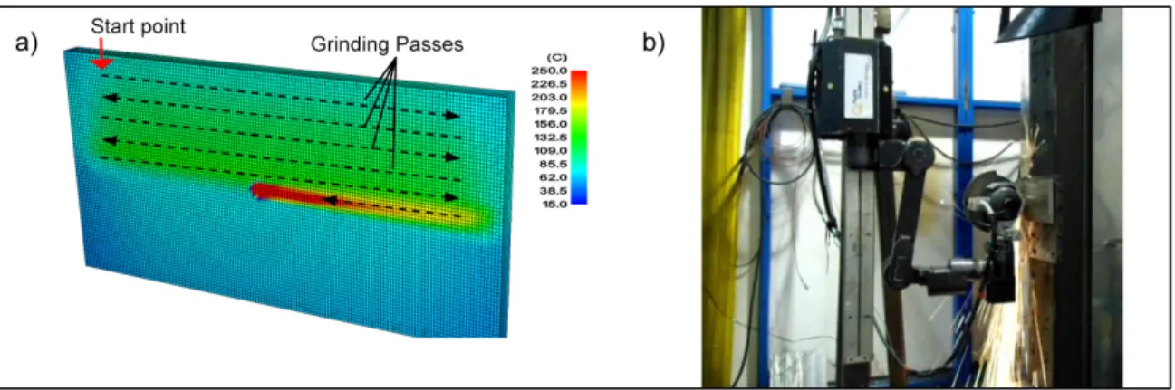
Figure 2-1 a) SCOMPI robot performing grinding operation during on-site blade modification to improve efficiency b) Laboratory setup with high-speed camera and lighting system ...27
Figure 2-2 a) Grinder motor torque constant, N=6000 rpm, α=-0.1535 %/ºC, b) Grinder motor losses ...31
Figure 2-3 Kinematics of cut ...32
Figure 2-4 Heat input model for a) shallow grinding, b) creep-feed grinding, (Anderson et al., 2008a) ...34
Figure 2-5 a) Heat input distribution, b) Uncut chip thickness over the wheel-workpiece interface ...36
XVIII
Figure 2-7 a) SCOMPI robot experimental setup, b) Grinding trajectories
(one layer of material removal) ...40
Figure 2-8 Position of subsurface thermocouples ...40
Figure 2-9 a) Full-size workpiece FE simulation, b) Test rig for determining the energy partition ratio ...42
Figure 2-10 Temperature-matching technique for finding the energy partition ratio, a, b) P = 1,500 W, Vf = 60 mm/s, depth = 5 mm; c, d) P = 1,500 W, Vf = 80 mm/s, depth = 12 mm ...43
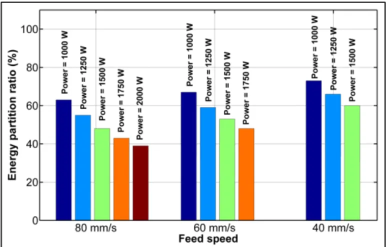
Figure 2-11 Energy partition ratio for different power levels and feed speeds ...44
Figure 2-12 Energy partition fitting model ...47
Figure 2-13 Experimental thermocouple temperature ...48
Figure 2-14 Finite element temperature distribution in the workpiece contact zone a) One step before the impact-cut, b) Impact-cut step (Power = 1,500 W, Feed speed = 40 mm/s) ...49
Figure 2-15 Contact temperature from finite element analyses and tests ...50
Figure 3-1 Laboratory setup of SCOMPI for grinding experiments, (a) disk wheel, (b) cup wheel ...61
Figure 3-2 Samples of the grinding wheel prepared for measurements, (a) disk wheel, (b) cup wheel ...61
Figure 3-3 (a) Confocal microscope with external light source, (b) disk wheel sample and (c) cup wheel ...62
Figure 3-4 (a) Optical image (b) topography of the same region ...63
Figure 3-5 Process for grinding wheel characterization ...64
Figure 3-6 Optical image enhancement through histogram stretching, (a) raw image, (b) after stretching ...65
Figure 3-7 (a) Butterworth filter, (b) original FFT image, (c) filtered FFT image ...66
Figure 3-8 (a) One channel optical image of the wheel surface, (b) zoom of the region in red, (c) after high-frequency noise removal, (d) after mean shift filtering ...67
XIX
Figure 3-9 (a) Optical image of grains, (b) binary mask of grains, (c) 3D topography of wheel as measured with the microscope, (d) 3D topography of grains with overlaid mask to remove the
bonding region ...68
Figure 3-10 Pitch and yaw angle with respect to cutting direction ...70
Figure 3-11 Normal extraction with plane fit method, (a) good result (grain with one face), (b) ambiguous result (grain with two faces) ...71
Figure 3-12 a) Grain surface without normal vectors, b) grain surface with vertex normal vectors ...71
Figure 3-13 a) Height topography image, b) pitch angle for the whole grain (left), only the cutting face (right), c) yaw angle for the whole grain (left), only the cutting face (right) ...72
Figure 3-14 a) Yaw angle distribution for the whole grain, b) for cutting face pixels, c) pitch angle distribution for cutting face pixels ...73
Figure 3-15 Distribution of (a) yaw angles and (b) rake angles at different power levels for disk wheel ...74
Figure 3-16 Distribution of (a) yaw angles and (b) rake angles in different grinding conditions for cup wheel ...75
Figure 3-17 Comparison of grain rake angle probability at different power levels for (a) disk wheel, (b) cup wheel ...76
Figure 3-18 (a) Grain protrusion and (b) grain width probability for disk wheel ...77
Figure 3-19 (a) Grain protrusion and (b) grain width probability for cup wheel ...77
Figure 4-1 Grinding kinematics, (a) traverse grinding, (b) idealized notch ...88
Figure 4-2 Test setup ...92
Figure 4-3 (a) Normal-speed video at 30 fps, (b) high-speed video at 6,000 fps, played at 30 fps (online version) ...93
Figure 4-4 Angular speed and force measurements ...95
Figure 4-5 (a) Normal and (b) lateral force signal, (c) friction coefficient, (d) impact cutting map ...96
XX
Figure 4-6 Impact regime at different power levels, (a) P = 500 W,
(b) P = 1,000 W, (c) P = 1,500 W, (d) P = 2,000 W ...98
Figure 4-7 Probability of number of impacts per turn ...98
Figure 4-8 (a) Scanning the grooves, (b) top view of a groove (image and measured), (c) sample 3D view ...99
Figure 4-9 (a) Analysis of scanned groove, (b) instantaneous MRR, (c) depth of cut ...100
Figure 4-10 Synchronized data for (a) power consumption measured from robot controller, (b) MRR from groove scan data, (c) angular speed from DAQ ...101
Figure 4-11 Error in cost function ...102
Figure 4-12 Predicted and measured grinding power ...104
Figure 4-13 Measured and predicted depth of cut at different power levels ...105
Figure 4-14 Measured and predicted average force at different power levels ...105
Figure A I-1 High speed camera setup used for observation of impact cutting ...123
Figure A I-2 Kinematics of uncut chips at each impact ...124
Figure A I-3 Surface of wheel a) 3D scan, b) Separated sections of wheel scan ...124
Figure A I-4 2D profiles and rake angles ...125
Figure A I-5 Finite element mesh ...126
Figure A I-6 Von-Mises stresses, depth of cut = 20μm a) rake angle = -10 degree, b) rake angle = -50 degree ...129
Figure A I-7 Normal force versus cutting speed ...129
Figure A I-8 Effect of initial temperature on cutting force ...130
Figure A I-9 Temperature contour during the chip formation ...130
Figure A I-10 Normal force versus depth of cut and rake angle ...131
XXI
Figure A I-12 Force ratio versus depth of cut and rake angle ...132
LIST OF SYMBOLS AND UNITS OF MEASUREMENTS
Symbol Units Description
A m2 Instantaneous cross-section area of undeformed chip
B Wb/m2 Flux density in the grinder iron armature
C J/K Specific heat capacity
c - Color value for mean shift algorithm
c - Average color value for mean shift algorithm
cf - Normalized cut-off frequency in Butterworth kernel function
CPower % Cost function for comparison of predicted and measured power
dg m Average grain size
ed J/mm2 Energy intensity function
E m Grinding wheel width
f Hz Rotational frequency N
F N Instantaneous normal grinding force N
F N Average normal grinding force T
F N Instantaneous tangential grinding force T
F N Average tangential grinding force
h m Depth of cut
0
h m Maximum depth of cut
H J/mm2 Heat flux distribution
I A Electrical current consumed by grinder
( , k)
i
K S S - Kernel function for mean shift algorithm
k,K W/(mK) Thermal conductivity
c
k N/m2 Cutting force coefficient e
k N/m Edge force coefficient
khys W/(kgHz) Hysteresis loss coefficient
keddy W/(kgHz) Eddy loss coefficient
KT Nm/A Torque constant of electrical grinder
KT(T) Nm/A Torque constant at a given temperature T
KT(Tref) Nm/A Torque constant at the reference temperature Tref
M - Grit size
n - Butterworth filter power
c
n - Number of impacts per revolution
N Hz Rotational frequency
P W Grinding power
m
P W Measured grinding power
m
XXIV
PM W Evaluated mechanical grinder power
Pfriction W Evaluated mechanical power to overcome friction
Pchip W Evaluated mechanical power to form the chip
PDrag W Power lost in drag and friction in grinder bearings
PFan W Power consumed to drives cooling fan in grinder
PCore W Power lost in the stator iron armature
Q Nm Nominal delivered torque at the grinder spindle
r - Normalized distance from center in Butterworth kernel function
R m Grinding wheel radius
0
R m Maximum grinding wheel radius
S,Schip m2 Surface of the uncut chip
Sk,Sk+1 - Pixel coordinate and color value in mean shift algorithm
t s Time
T K Temperature
T∂ K/m Temperature gradient
Tref K Reference temperature
u J/m3 Grinding specific energy
uch J/m3 Chip formation specific energy
upl J/m3 Plowing specific energy
usl J/m3 Sliding specific energy f
v m/s Feed speed of the robot
V,Vchip m3 Volume of the uncut chip
s
V m/s Peripheral speed of the grinding wheel
w m Width of cut
x m Instantaneous undeformed chip width X m Longitudinal coordinate of the groove
x
Δ m Wheel advance per turn in feed direction w
Z m3/s Material removal rate T
α %/C Negative reversible temperature coefficient
α - Energy partition model coefficient
β - Energy partition model coefficient
γ m Abrasive grit width
ρ Kg/m3 Mass density
ε - Energy partition ratio
δ m Uncut chip thickness
θ rad Cutting angle
μ - Friction coefficient
ω rad/s Rotational speed of grinder spindle
INTRODUCTION
All machining operations involve a material removal process. Although the process varies in different types of machining, understanding this removal mechanism is a key step toward achieving higher efficiency in the process. Grinding, unlike other machining processes, can be defined as fairly shallow removal of material, usually in order to reach high accuracy in the finishing phases of manufacturing or rectifying processes. Grinding is among the most important machining processes because it is performed in the final stages of manufacturing and has a direct effect on product quality. Efforts in modeling and simulating this process can thus yield a significant practical return on investment.
Numerical methods like finite element analysis (FEA) have been applied to a wide range of engineering fields to model and simulate many physical phenomena. Empirical models are also commonly used to predict any complex process for which there is no possible analytical solution. Both methods have thus become strong tools in industry in order to predict and understand process behavior and to reduce trial-and-error practices.
The fact that the material removal process in grinding is composed of innumerable micro-cutting actions by random grains makes grinding a difficult task to model. This difficulty becomes even more challenging when a flexible robot is the manipulator holding the grinder. Dynamic effects and stiffness of the robot structure add to problem complexity. Hence, a comprehensive study of the robotic grinding process is necessary and must consider the flexible holding structure of the grinding robot.
Organization of thesis
This research work is presented as a manuscript-based thesis and divided into four chapters. Chapter 1 gives information about the problem providing the basis for this research, outlines the research and states the objectives defining the scope of study. Background to this
2
research work is also discussed. The methodology followed is described, emphasizing major assumptions and considerations for each model.
Chapter 2 presents the first journal article. A thermal finite element model is developed to obtain the temperature distributions in the workpiece during the robotic grinding process. The effects of different loading conditions and the particular cutting regime occuring with the robot under study are considered under the boundary conditions applied. An energy partition model applicable to the process is introduced and verified through a series of tests. Temperature results from the model showed good agreement with the test results.
Chapter 3 presents the second journal article. In this work, the grain topography of the grinding wheels used in the process is obtained. A new method is developed for distinguishing the grains from the bonding material using image processing techniques in overlaid optical images of the measured surface. Having thus determined the geometry of individual grains, the yaw and rake angles of the grain faces involved in the cutting action are extracted. The distribution and mean value of these angles are evaluated under different operating conditions. The grain geometry data is vital for micro-scale simulation of the cutting action in the grinding process. This is an ongoing area of research in this project.
Chapter 4 presents the third journal article. Enhancements are made in determining the emprical coefficients of an existing force model for the process. Grinding with the robot under study was seen to be interrupted at each revolution of the wheel. The number of impacts per turn is determined at different grinding power levels through tests in which the force signal is measured. Also, using the friction-chip energy ratio of the process obtained in the first article, the empirical coefficients to use are more closely determined. The predicted depth of cut and average normal force showed a very close correlation with the results from test measurements.
CHAPTER 1
RESEARCH OUTLINES AND OBJECTIVES
1.1 Problem definition
Hydro turbines have been widely used for power generation for many years in North America. With about 40% of Canada’s water resources, Québec provides a major portion of the electricity generated by hydropower (Hydro-Québec, 2010). Figure 1-1 shows a view of a typical hydro turbine and its generator.
One typical type of damage to hydro turbines is cavitation on turbine blades, which is a major problem in turbine maintenance. High repair costs for these blades and the long repair time due to their enormous size have long been a major issue. In the late 1970s, Hydro-Québec started designing a robot capable of handling the entire repair procedure for cracks
Figure 1-1 Schematic view of hydro turbine (Top-alternative-energy-sources, 2010)
4
and defects in turbine blades. The robot was developed by IREQ, Hydro-Québec’s research institute. It has the ability to reach otherwise inaccessible areas of the installed blade without requiring their disassembly (see Figure 1-2) (Hydro-Québec, 2004). To achieve such versatility, a light-weight, flexible robot was required to meet the need for on-site maintenance of hydro turbine blades. The robot developed has effectively reduced turbine down time and saved a considerable amount of money during turbine maintenance. The robot is named “SCOMPI”, which stands for “Super COMPact Ireq robot”. With a total weight of about 33 kg, it has 6 degrees of freedom and is capable of performing on-site plasma gouging, welding, grinding and hammer pinning. The grinding process with this robot is designed for parts in difficult-to-reach locations, such as turbine blades, or unmovable parts in special environments, like underwater gates. It is difficult or even impossible to grind such parts with conventional grinding machines due to their surroundings.
Because of its light-weight design, the robot has a low-stiffness structure given the task force compared to conventional grinding machines. Consequently, unwanted vibrations and deformation of the arm are likely to occur during the process. Due to the robot’s characteristics, loss of accuracy and non-uniform material removal may result when grinding.
Figure 1-2 SCOMPI during on-site maintenance (Charles Gagnon, 2010)
5
Since a fine surface finish and accurate dimensions are essential for efficient turbine blades, the grinding process with SCOMPI requires great care. The desired material removal is achieved through a multi-step procedure with dimensions controlled precisely at each step.
1.2 Scope of study and objectives
In order to improve process efficiency, a better understanding of the robotic grinding process discussed above is crucial. The main purpose of this research is to improve the quality and precision of grinding performed by SCOMPI. The goal is thus to develop or improve numerical and empirical models in order to better predict the process.
An important issue in all grinding processes is thermal defects in the workpiece due to excessive heat generated during the process. This may be even more important when grinding is performed by robots due to the more dynamic nature of robotic grinding. Hence, the first part of this work relates to thermal aspect of the process. This includes quantifying heat input to the workpiece using finite element analysis and testing. FE simulations of grinding usually ignore the dynamic effect of the holder’s structure. This assumption is made based on conventional grinding machines with a rigid structure. Boundary conditions related to the parts attached to the machine are thus assumed constant. In robotic grinding and especially with the light, flexible structures in this study, the effects of low manipulator stiffness cannot be ignored in simulations. If the structure of the machine is not rigid, the depth of cut will not stay constant. Plastic work, friction forces and generated heat may also vary over time. Thermal simulations must include heat flux dynamics for appropriate solutions. Therefore as of the first objective, a macro-scale FE model is developed with dynamic boundary conditions representing the robotic grinding process. The aim is to investigate the temperature distribution in the workpiece due to the process. The results are expected to make it possible to predict any thermal defects produced in the workpiece due to the dynamics of robotic grinding.
6
Another step toward acquiring the necessary understanding of the process is to have a micro-scale view of the grinding process. Material removal in grinding is a combination of numerous micro-cuts in the wheel-workpiece contact zone. Microscopic modeling of grinding focuses on the effects and interactions between individual grains and the workpiece surface. It is thus crucial to investigate the geometry of cutting edges, meaning the orientation and protrusion of grains. The second objective of this study is to characterize two wheels commonly used in the SCOMPI grinding process. A non-contact method with a confocal scanning laser microscope is used to obtain the wheel topography. The necessary steps are taken to remove the bonding material from measurements. Grinding wheels are characterized under different operating conditions. A comprehensive view of the wheel topography is achieved, including grain density, grain width and protrusion height, as well as the rake and yaw angles of the attacking faces of grains. The resulting geometry of cutting edges from this study will be used in a future study for micro-scale simulation of the process.
The last part of this study is devoted to an empirical model for force prediction at a specific material removal rate. As mentioned earlier, the main difference between conventional grinding and robotic grinding is tool holder rigidity. Lower rigidity causes non-uniform material removal during robotic grinding. An accurate force model that considers the correct process dynamics will thus help the robot controller to better maintain desired process characteristics like depth of cut. An existing force model is further analyzed with an emphasis on the effect of cutting regime and energy concepts.
In conclusion, a FE macro-scale model is developed to determine temperature distribution in the workpiece during the process. The thermal results are used to predict thermal damage and evaluate material behavior for a FE micro-scale model. In order to properly investigate material removal mechanism by the micro-scale model, having the information of cutting edge in the grinding wheel is necessary. Therefore, wheel topography study is performed and statistical geometries of grains are extracted. Finally, some enhancement on the process force model is performed to improve process quality and precision.
7
1.3 Background
Numerical simulation is more complex to perform for grinding than for other machining processes. The reason is the random size and shape of the grits and their cutting edges. Basically, two approaches are employed to overcome this difficulty. One approach is to investigate the process through macro-scale simulations in which there is no need to know the geometry of cutting edges. Instead, the effect of the cutting process is applied in the model without going into details regarding the material removal process. In the resulting models, the effect of the grinding wheel is usually represented by a heat source moving over the workpiece surface (Jaeger, 1942). The other approach is to investigate the process through micro-scale simulations which focus on interactions between a single grit and the workpiece surface. While macro-scale models are more of a general look at the process, micro-scale models deal with the details of grain-workpiece interaction. (Brinksmeier et al., 2006; Doman et al., 2009b; Mackerle, 2003) have produced thorough reviews of finite element simulations of machining and grinding.
1.3.1 Thermal modeling of grinding
Early measurements of grinding forces and specific energy in the 1950s revealed that grinding has higher specific energy than other machining processes like turning or milling (Stephen Malkin, 2008). This means that for a specific volume of material removed by grinding, much more power is consumed than by any other machining process. Commonly, much more heat is thus generated, and consequently the rise in workpiece temperature is greater. If the temperature exceeds a critical limit, phase transformation occurs in the workpiece. Due to this phase transformation, brittle untempered martensite is formed on the surface. This is referred to as “workpiece burn” and has a bluish color. The thickness of this martensite layer depends on the amount of heat applied and how readily it is conducted through the workpiece (Malkin and Guo, 2007). Other thermal defects in the workpiece due to high temperature are micro-cracks, residual stresses, warping, bending and twisting. That
8
is why thermal damage is of utmost concern in the grinding processes and the subject of considerable study.
Figure 1-3 shows the key inputs to and expected results from a general macro-scale model of robotic grinding. However, only thermal aspects of macro-scale modeling are investigated in this thesis. As explained earlier, an important parameter to consider in quantifying heat flux is the energy partition to the workpiece (Chen and Xu, 2010; Hadad et al., 2012; Kohli et al., 1995). A correlation for the heat flux is derived, usually based on the consumed power or specific energy, and calibrated using test data for the process condition (Guo and Malkin, 1999; Mohamed et al., 2011).
In macro-scale models, the finite element mesh covers the workpiece. The cutting zone is considered to be a very thin area compared to the workpiece. The grinding wheel is then represented by a heat flux moving along the workpiece surface. The heat flux may have different distributions, like uniform or triangular, based on the grinding parameters. The effects of a liquid coolant or natural air cooling are modeled by heat convection on the surface of workpiece (Hoffmeister and Weber, 1999; Li and Li, 2005; Mahdi and Liangchi,
Figure 1-3 Key inputs and outputs in macro-scale modeling of grinding process
9
1995; Mao et al., 2010; Parente et al., 2012). The general model with different heat fluxes is shown in Figure 1-4. Given the impact cutting phenomenon and dynamic force response in robotic grinding, real dynamic power consumption must be considered rather than just the mean value since it affects directly the heat flux entering the workpiece. The applied heat flux is thus not constant over time as it progresses across the workpiece surface.
Any numerical simulation must be validated through tests or analytical solutions. Online temperature measurement during grinding is the most trustworthy test method for validating thermal simulations of the grinding process. In fact, temperature measurement during grinding is not only crucial to validate thermal simulation results but is also needed to investigate and determine the energy partition for heat modeling (Kohli et al., 1995). Grinder power consumption should also be recorded to obtain the specific energy of the process. This is necessary for calculating the energy partition ratio.
The heat generated in the grinding process is highly transient and close to the wheel contact area. A highly sensitive sensor should thus be placed near this area to measure the actual temperature impinging on the workpiece material. Common temperature measurement techniques used for grinding are embedded foil thermocouples and thermal imaging. Thermocouples are frequently used to validate thermal simulations of the grinding process (Dai et al., 2000; Lefebvre et al., 2012; Li and Li, 2005; Wang et al., 2003). They have
Figure 1-4 Macro-scale thermal finite element model (Doman et al., 2009b)
10
proven to be a fast, appropriate measuring tool for such transient thermal conditions. The other common method mentioned, thermal imaging, involves measuring the infrared radiation emitted from the workpiece by means of a thermal camera or any other appropriate CCD sensor (Anderson et al., 2008b; Hwang et al., 2003; Mohamed et al., 2012a). The primary drawback in thermal imaging is the interference of any other body, which blocks radiation from the main object. Depending on the workpiece and process conditions, both methods have been extensively used in earlier studies.
1.3.2 Single-grit chip formation model for grinding
The other approach in grinding simulations is micro-scale FE modeling of the process. The purpose is to develop a finite element model capable of simulating chip formation and finding the appropriate relations among applied force, friction and local plastic deformations in the contact area for individual grains. Micro-scale modeling of grinding involves large deformations in geometry, in addition to material and boundary non-linearity. Figure 1-5 shows the key inputs that should be provided for a micro-scale model of robotic grinding as well as the expected results.
Figure 1-5 Key inputs and outputs in micro-scale modeling of grinding process
11
Three important general aspects to be considered in finite element simulations of all metal cutting processes are material behavior, the friction model and the chip separation criterion. Since very large deformations and high heat generation usually occur simultaneously in the process, selecting the appropriate material model is crucial. Furthermore, friction and the chip separation criterion play major roles in chip formation, cutting forces and generated heat in finite element simulations.
Material behavior in metal cutting is known to be one of the dilemmas in simulating the process. Due to excessive strain, large strain rate and high temperature, the material does not respond by common elastic-plastic behavior. One well-known model of plasticity, the visco-plastic model, has been found to be most appropriate. Numerous constitutive models in the literature have been used by researchers to determine the visco-plastic material flow in machining processes. In most of them, the influences of strain rate and temperature are considered for calculating the effective stresses. (Fang, 2005a) compared 18 engineering materials and concluded that strain rate hardening has less effect on flow stress than the other factors, i.e., strain hardening and thermal softening. A list of common constitutive material models for stress flow can be found in (Grzesik, 2008). The most important and commonly used material models are those of (Zerilli and Armstrong, 1987), (Oxley, 1989) and (Johnson and Cook, 1985b).
In simulating the chip formation phenomenon, as the tool advances into the workpiece, the material ahead of the tool tip must be pushed away so that the chip and new surface can form. This involves separation of the finite element mesh during the solution. Basically, in order to handle material separation in finite element models, three techniques have been used: node separation criteria (geometrical or physical), adaptive re-meshing and element deletion with a damage law. Any one or a combination of these techniques can be implemented to form the chip in metal cutting simulations. Node separation criteria are based on splitting nodes on a predefined path. Separation occurs when a specified law or rule is satisfied. Studies have used various physical parameters for separation thresholds (Carroll and Strenkowski, 1988; Iwata et al., 1984; Lin and Lin, 1992). Adaptive re-meshing is a local
12
(Ozel and Zeren, 2005) or global re-meshing (Yen et al., 2004) of the workpiece with respect to an activation criterion, i.e., a limit for change of angles in elements or a constant time interval. In element deletion, a damage law is applied to control the elements in the distorted zones. Any element that reaches the limit is deleted from the mesh. The most well-known damage law and one frequently used in metal cutting simulations is that of (Johnson and Cook, 1985a). This damage law has been implemented in several metal cutting simulations for chip formation modeling (Guo and Yen, 2004; J. Zouhar, 2008; Pantalé et al., 2004; Zeren, 2004).
The other major aspect in FE simulation of metal cutting processes is the tool-workpiece friction model, which is still a matter of interest in recent studies. According to (Ozel and Altan, 2000), in conventional machining, friction exists in two locations: between the flank face of the tool and finished surface of the workpiece, and between the rake face of the tool and the chip formed. However, in high-speed machining like orthogonal cutting and grinding, flank face friction is much lower than rake face friction. The effective friction in high-speed machining and grinding will thus only be between rake face of the tool and the chip formed. Basically, two distinctive zones in the contact region of the rake face are considered: a sticking region near the tool tip and a sliding region over the remaining contact length. Friction in the sliding region is explained by Coulomb’s law. However, since friction force clearly cannot exceed the shear limit of material, friction is constant and equal to the shear limit in the sticking region. This is one of the basic models. Many other studies deal with this matter (Arrazola et al., 2008; Arrazola and Özel, 2010; Bonnet et al., 2008; Ozel, 2006; Shi et al., 2002).
From a simulation standpoint, the metal cutting process closest to material removal in grinding is orthogonal cutting with a negative rake angle. (Sevier et al., 2007) used finite element analysis to investigate the plastic deformations caused by machining, considering a wide range of rake angles (-50 to +50 degrees) in their simulations. (Ohbuchi and Obikawa, 2003) also tried to simulate the grinding mechanism by introducing a FE model of orthogonal cutting with a large negative angle and an updated Lagrangian formulation. The authors
13
found that the cutting speed and grinding parameters like depth of cut greatly influence the chip formation process. In another study, (Doman et al., 2009a) presented a three-dimensional FE model to investigate the sliding and plowing phases of material removal in grinding. The normal and tangential forces from the FE model were compared to scratch test results to validate the model proposed. (T.T.Opoz, 2010) considered a negative-rake-angle tool in orthogonal cutting to represent single-grit cutting in grinding. An explicit solver is utilized, and the Johnson-Cook (J-C) material model is applied in conjunction with the J-C damage law to perform the chip formation process. 2D and 3D models are simulated by means of the ALE formulation and adaptive re-meshing technique to avoid element distortion. It is confirmed that J-C is a suitable material and damage model for machining processes. Figure 1-6 shows the stress contour in 2D and 3D simulations from this study.
Extensive finite element studies have been conducted on chip formation in other types of machining processes (Altan and Vazquez, 1997; Mackerle, 2003; Mackerle, 1998). Chip formation modeling in grinding remains a complex problem, however, due to the random position and unpredictable geometry of grains. One solution implemented to solve this problem is to modify the finite element model of chip formation in other machining processes in a way that represents the single-grain action in grinding. Study in this field is clearly lacking and most grinding FE simulations focus on macro-scale modeling of the process.
Figure 1-6 a) 2D chip formation model, b) 3D chip formation model (T.T.Opoz, 2010)
14
1.3.3 Grinding wheel topography
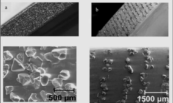
Grinding wheels are composed of innumerable tiny abrasive particles, which remove material from a surface. Although some recent efforts have been directed toward positioning abrasive particles in specific patterns on the surface of grinding wheels (Aurich et al., 2003; Aurich et al., 2008), in most conventional wheels, the particles, named “grains” or “grits”, are positioned randomly in the wheel structure and have different shapes and edge angles (see Figure 1-7). That is why the grinding process remains among the least understood manufacturing processes and is extremely difficult to model. In order to overcome this difficulty, grinding wheel surface characteristics must be determined, a necessary step for any sort of micro-scale simulation of grinding. This means determining the geometry of cutting edges as well as the position and density of grains. There are basically three main
groups of studies that employ different strategies to deal with this random cutting edge problem.
Figure 1-7 Grit positioning in the grinding wheel a) standard wheel, b) defined-grain-pattern wheel (Aurich et al., 2008)
15
The first group of studies assumes that grains are of some basic shape, such as spheres, pyramids, cones or prisms (Badger and Torrance, 2000; Fengfeng and Zhou, 2005; Transchel et al., 2014). The second group of studies develops a mathematical description for the wheel topography based on virtual grinding wheel modeling. The mathematical models are developed for different types of wheel, like diamond wheels (Koshy et al., 1993; 1997), CBN wheels (Li et al., 2013), etc. The grinding wheel topography models developed in this group cover a wide range: from 1D and 2D models to 3D representations of wheel surface (Doman et al., 2006). These models are generally used for kinematic analysis of the grinding process (Liu et al., 2013; Nguyen and Butler, 2005). The third group of studies focuses on obtaining the wheel topography from direct measurements of the wheel’s surface. There are two main measurement methods: contact and non-contact (Darafon, 2013). In both methods, an important initial step is to separate grain topography data from the bonding data. This is achieved either by preparation of wheel to remove the bonding material before measurement (Xie et al., 2011) or by applying detection and filtering techniques after measurement (Darafon et al., 2013). In most contact methods, it is hard to distinguish between the grains and the bonding material. Some studies use a method called “highest point among eight neighbors” to define the grains. This introduces another difficulty, i.e., the need to use an optimum sampling distance. If the sampling distance chosen is smaller than the optimum value, the number of grains may be overestimated by instead detecting the cutting edges (Blunt and Ebdon, 1996). Figure 1-8 illustrates how the sampling distance affects the grain count by the “highest point among eight neighbors” method.
16
In non-contact methods, grain detection can be performed using the intensity of the reflected measuring beam. However, this is applicable only if grains have high reflectivity in order to differentiate them from the bonding material, as in diamond wheels (Cui et al., 2013). Environmental light may also affect the results. Another method is to use a scanning electron microscope (SEM), which makes it possible to distinguish between the grains and bonding material (Kapłonek and Nadolny, 2013). The small chamber for specimens and the high costs of a SEM are disadvantages of this method.
1.3.4 Grinding force model
As explained earlier, the robotic grinding under study is for field repair purposes on hydropower equipment. The process is designed to perform high material removal rate grinding as well as attain high surface finish quality and accuracy. The robot’s flexibility due to its light-weight structure and track-based design leads to material removal through impact cutting. Conventional position control systems thus cannot be employed here to achieve high
Figure 1-8 Effect of sampling distance in detecting the number of grains (Nguyen and Butler, 2008)
17
removal rates and high precision. Instead, a hybrid force-position controlled material removal rate (CMRR) strategy is used to obtain the final profile (Hazel et al., 2012a). The grinding force model is a crucial part of this CMRR strategy. Special care must be taken to ensure that all dynamic effects caused by low robot rigidity are included in the force model. In other words, the desired material removal rate (MRR) is obtained by regulating the grinding power. The force model provides the correlation between the MRR and grinding power.
Figure 1-9 is a block diagram of the controller. First, the task planner calculates the desired MRR for the target depth of cut based on the process kinematics and other related parameters, such as wheel geometry. Second, the calculated MRR is correlated to the target force and grinding power that are used to control the robot. A wheel wear model is also employed to apply the necessary adjustments due to changes in wheel geometry during the process.
(Brinksmeier et al., 2006; Tönshoff et al., 1992) summarized early grinding studies in the literature. Some are based on comparative experiments with no mathematical expression for force (Malkin and Cook, 1971). Others tried to established a mathematical expression to predict the force based on chip thickness (Snoeys et al., 1974), the stochastic distribution of
Figure 1-9 Hybrid force-position controller (Hazel et al., 2012b)
18
cutting edges (Werner, 1973) or chip formation and friction concepts (Lichun et al., 1980). However, these models all lack the effects of grinding time and coolant.
Generally, since random grains participate in the grinding removal action, it is impossible to develop a fully analytical force model for the grinding process. The dynamics of robotic grinding also make force prediction more difficult. Most grinding force models fall into one of three categories: empirical, semi-analytical or grit-based. Empirical models propose a mathematical model for force, composed of major process parameters supplemented by regression exponents and multipliers determined experimentally (Johnson et al., 2008; Liu et al., 2008; Mishra and Salonitis, 2013; Winter et al., 2014). Although empirical force models are widely used for industrial applications, their coefficients must be determined for each specific operating condition. Their main drawback is thus the time and cost of tests needed for each combination of grinding wheel and workpiece material. While empirical models largely depend on test data, semi-analytical models reduce this dependency by incorporating process kinematics into the model. These models are normally supported by an analytical chip thickness model (Agarwal and Venkateswara Rao, 2013). Certain studies in this category construct the force model from chip formation, friction and sometimes plowing components (Patnaik Durgumahanti et al., 2010; Yao et al., 2014). The third category of grinding force models is based on the micro-interaction between wheel and workpiece. Single-grit cutting force models are developed and extended based on a wheel topography model to obtain the overall grinding force (Chang and Wang, 2008; Hecker et al., 2007; Wang et al., 2014).
1.4 Summary
This section explained the initial reasons and drivers for the research project. The scope of this study and areas of research were also outlined. Then background was presented on other work related to this research problem.
19
Two grinding FE modeling approaches, i.e., macro-scale and micro-scale, were introduced. Key inputs and outputs of these approaches to modeling robotic grinding were explained. Though numerous studies have been conducted on the simulation of metal cutting processes and conventional grinding, less attention has been given to dynamic conditions in FE modeling of robotic grinding. After reviewing several studies in this area, the author found no FE model specifically related to the material removal mechanism in robotic grinding.
The importance of studying grinding wheel topography was highlighted. Contact and non-contact methods in the literature used for measuring wheel topography were briefly introduced. Though many methods have been used by researchers to develop the requisite knowledge of cutting edges in grinding process, there is still room for developments, especially regarding techniques for distinguishing grains from the bonding material. Also, no study was found on grinding wheel topography that considered only the attack side of the grains for characterization purposes.
Why the control strategy (CMRR) used for the process requires an accurate force model is clarified. The force models for conventional grinding in the literature include empirical, semi-analytical and grit-based models. Since the conventional force models are not applicable to the robotic grinding process under study, an appropriate force model is essential in order that the process achieves both high surface quality and accuracy. The dynamics of the robot is at the core of this force model. The next three sections of this thesis present developments and the results obtained in this research in the form of three journal articles published or submitted for publication.
CHAPTER 2
EXPERIMENTAL AND FINITE ELEMENT ANALYSIS OF TEMPERATURE AND ENERGY PARTITION TO THE WORKPIECE WHILE GRINDING WITH A
FLEXIBLE ROBOT
Amir Masoud Tahvilian1, Zhaoheng Liu1*, Henri Champliaud1, Bruce Hazel2 (1)Department of Mechanical Engineering, École de technologie supérieure,
Montréal, Québec, H3C 1K3, Canada
(2)Expertise Robotique et civil, IREQ, Hydro-Québec’s research institute
Varennes, Québec, J3X 1S1, Canada
This article is published in “Journal of Materials Processing Technology”, volume 213, issue 12, December 2013, Pages 2292-2303
Highlights
• A new representation of heat source is developed for thermal analysis of a flexible robotic grinding.
• Energy partition ratio is adjusted for a flexible robotic grinding using temperature-matching technique.
• A modified empirical model from the literature and a new formula are proposed to determine the energy partition applicable to this study.
• Dynamic effect of robotic grinding predicted temperatures 15% higher than when average parameters are considered.
2.1 Abstract
Grinding processes performed with flexible robotic tool holders are very unlike conventional types of grinding because of low stiffness of the robot’s structure. A special flexible robotic grinding process is used for in situ maintenance of large hydroelectric equipment for bulk material removal over large areas rather than as a finishing step, as is the case for most
22
conventional grindings. Due to the low structural stiffness of tool holder, cutting is interrupted at each revolution of wheel during the grinding process. In this study, an investigation is carried out to determine the temperatures and energy partition to the workpiece for the above-mentioned flexible robotic grinding process by a three-dimensional finite element thermal model. Experiments were undertaken using embedded thermocouples to obtain the subsurface temperature at several points in the workpiece during the process. Then, energy partition to the workpiece was evaluated using a temperature-matching method between the experimental and numerical results. This ratio is used for predicting the temperature field at the wheel-workpiece interface with a relevant heat source function. Kinematics of cut and the flexible robot’s dynamic behavior are considered in applying the heat input to the model. The energy partition to the workpiece in this specific flexible grinding process is found to be lower than for analogous conventional precision grinding processes. Two models, one from the literature and one from the power model of the process, are modified and proposed for determining the energy partition. The results showed that the energy partition ratio decreases by increasing the process power. Also, this ratio slightly decreases at higher feed speeds. In addition, lower temperatures were seen at higher powers due to the lower intensity of heat input over a larger contact area. Experimental observations show close agreement between simulated contact temperatures and measured results.
Keywords: Robotic grinding; finite element analysis; energy partition; contact temperature
2.2 Introduction
Grinding has much larger specific energy in material removal than other machining processes, leading to a higher temperature at the wheel-workpiece interface. High temperature can cause thermal damage, such as burning and phase transformation, which adversely affect workpiece surface characteristics. High temperature is also an important factor in grinding wheel wear rates and significantly affects the mechanical behavior of workpiece material due to thermal softening effects. Many studies have been conducted to
23
determine the temperature field in the workpiece during conventional grinding processes. They are usually based on a model by Jaeger (1942), who proposed a heat source of constant intensity moving over a semi-infinite workpiece surface. Brinksmeier et al. (2006) presented an overview of all types of models and simulations for grinding process, including analytical and numerical models.
Thermal simulation of the grinding process generally involves measuring the power consumed during the process, determining the ratio of energy transported into the workpiece and defining the heat input function for the particular surface. The most challenging of these three tasks is determining the energy partition into the workpiece for all grinding parameters and conditions. Rowe et al. (1988) were among the first who introduced the concept of heat partitioning in thermal modeling of grinding process. The four main sources of heat dissipation in the grinding process are the grinding wheel, the workpiece, chips and coolant. Specifying the amount of heat entering the workpiece is a key rule for any thermal simulation of grinding processes.
Finite element (FE) methods have proven to be a reliable approach and are used extensively by researchers for thermal simulations of grinding. Several FE models with different heat functions are used to predict the temperature distribution in the workpiece. Doman et al. (2009b) summarized some FE approaches used for grinding modeling and categorized them into macro- and micro-scale models. Early simulations made a number of simplifying assumptions to obtain a two-dimensional (2D) model. However, with computer power increasing in recent years, more complex three-dimensional (3D) models have been developed and solved with fewer assumptions. Mahdi and Liangchi (1995) used FE to predict phase transformation in the workpiece assuming, surface grinding as a 2D process with a triangular heat source profile. In other study, Mamalis et al. (2003a) used a similar model with a rectangular heat flux function to investigate effect of different grinding wheels on maximum surface temperature in the workpiece. Jin and Stephenson (2004) studied transient heat transfer for high efficiency deep grinding with 3D model, evaluating effect of convective cooling on the side walls of workpiece in contact temperature. Mao et al. (2010)
24
performed a 3D thermal simulation proposing a parabolic distribution for heat flux in the contact zone rather than a triangular one. Mohamed et al. (2012b) showed the importance of using the accurate grinding power for calculating the heat flux in a numerical simulation of heat transfer in grinding process. The authors used instantaneous grinding power, average grinding power and calculated power from tangential force and cutting speed to obtain the contact temperature and compared it with experimentally measured temperatures. It is found that in steady-state condition instantaneous power and calculated power give the best match results with experiments where average power underestimates the temperatures. Although many thermal models for conventional grinding exist in the literature, less attention has been paid to grinding processes more recently performed by flexible robots.
2.3 Energy partition background
Energy partition is defined as the ratio of the energy that enters the workpiece to the total energy consumed by the grinding process. The energy partition largely depends on operating parameters, as well as on grinding wheel and workpiece thermal properties. Numerous studies have been conducted to determine the energy partition to the workpiece under various grinding conditions for conventional machines. A number of researchers commonly used a temperature-matching method to investigate this ratio. Using this method, the energy partition is found by matching temperatures measured during the process with the results of a thermal model or experiments. Kohli et al. (1995) found a ratio of 60-85% for conventional aluminum oxide wheels and 20% for resin bond cubic boron nitride (CBN) wheels in regular grinding. In a similar study, Guo and Malkin (1999) obtained same results with the extension that, energy partition ratio is reduced to 5-8% for vitrified CBN wheels. Guo et al. (1999) also verified that only 4.0-8.5% of total energy enters into workpiece for grinding with vitrified CBN wheels. Such a low ratio is attributed to the high thermal conductivity of the CBN grains and the enhanced fluid flow in vitrified wheels. Anderson et al. (2008c) determined the ratio of 70-90% for dry grinding with an aluminum oxide grinding wheels. Chen and Xu (2010) also performed temperature matching technique for high speed grinding and found a range of 30-75% under different grinding conditions with a brazed diamond
25
wheel. (Mohamed et al., 2011) found a relation between surface roughness of the finished workpiece and grain radius of the wheel in the contact zone. The authors used this correlation to update an existing energy partition model which needs estimation of grain radius. (Hadad et al., 2012) also reported a study of energy partition of grinding in dry, minimum quantity lubrication (MQL) and fluid environments for a hardened 100Cr6 steel workpiece. The authors found a 82%, 75% and 36% ratios for grinding with aluminum oxide wheel in dry, MQL and fluid cooling respectively. Whereas these ratios are reduced to 52%, 46% and 14% for CBN wheel due to high thermal conductivity of CBN abrasive.
Some investigations are conducted to relate the energy partition to relevant grinding parameters, such as process specific energy or workpiece and grinding wheel material properties. Material removal in grinding is performed by the action of many grains and can be divided into three stages—sliding, plowing and chip formation—as proposed by Hahn (1962). Consequently, grinding specific energy (u) can be divided into three fractions based on the stages above:
ch pl sl
u = u + u + u (2.1)
Malkin and Anderson (1973) found that in dry shallow conventional grinding about 55% of chip formation energy and almost all sliding and plowing energy enter the workpiece. Therefore, the energy partition can be rewritten in the form of specific energy (Malkin S., 2008,),
0.55 0.45
energy entering the workpiece -total consumed energy
pl sl ch ch
u u u u u
u u
ε = = + + = (2.2)
where u is the specific energy and uch is the chip formation specific energy found to be
3
13.8 /J mm for grinding of steel workpieces (Kohli et al., 1995). This model is applicable to
26
grinding wheel is used. It is because of high thermal conductivity of CBN (500~1300 Wm-1K-1) compared to aluminum oxide (36 Wm-1K-1) which causes significant conduction of heat into the wear flat grain at the wheel-workpiece interface in the former case (Lavine et al., 1989). Therefore, although the assumption of remaining plowing energy in the workpiece still stands, not all the sliding energy is conducted in the workpiece when grinding with CBN wheels.
All studies on the temperature and energy partition were for conventional grinding processes with rigid structures, none for specific flexible robotic grinding process. In this study, a 3D transient thermal FE code is developed to account for heat generation due to a robotic grinding operation. The aim is to study thermal conditions during the discontinuous material removal, called “vibro-impact cutting”, which is the way a flexible robot performs grinding and should be distinguished from chatter in conventional machining. First, the energy partition ratio is obtained, using the proper input heat function, through several full-size workpiece simulations and comparison with test results. The predicted energy partition value is correlated with the power model implemented in the robot controller, which has been verified in several field trials (Hazel et al., 2012a). Then, on a smaller model for the contact zone, the input heat function is adjusted to the dynamic cutting conditions based on the observed impact-cutting behavior of the robot during the grinding process to find the exact contact temperature. Knowledge of the temperature distribution is important not only for studying workpiece burns and other thermal damage, but also for the ongoing study of chip formation to predict how thermal softening affects workpiece material behavior.
2.4 SCOMPI robot
This study concerns thermal aspects of a traverse surface grinding performed by a light flexible robotic tool holder. The robot, named “SCOMPI” (Super COMPact robot Ireq), is developed by IREQ, Hydro-Quebec’s research institute, and has been used mainly for in situ maintenance of hydro turbine runners (Hazel et al., 2012b). SCOMPI is a portable, multi-purpose, track-based 6-degree of freedom robot manipulator weighing 33 kg. The robot is