HAL Id: hal-01292939
https://hal.archives-ouvertes.fr/hal-01292939
Submitted on 24 Mar 2016
HAL is a multi-disciplinary open access
archive for the deposit and dissemination of
sci-entific research documents, whether they are
pub-lished or not. The documents may come from
teaching and research institutions in France or
abroad, or from public or private research centers.
L’archive ouverte pluridisciplinaire HAL, est
destinée au dépôt et à la diffusion de documents
scientifiques de niveau recherche, publiés ou non,
émanant des établissements d’enseignement et de
recherche français ou étrangers, des laboratoires
publics ou privés.
A Seven-degrees-of-freedom Robot-arm Driven by
Pneumatic Artificial Muscles for Humanoid Robots
Bertrand Tondu, Serge Ippolito, Jérémie Guiochet, Alain Daidié
To cite this version:
Bertrand Tondu, Serge Ippolito, Jérémie Guiochet, Alain Daidié. A Seven-degrees-of-freedom
Robot-arm Driven by Pneumatic Artificial Muscles for Humanoid Robots. The International Journal of
Robotics Research, SAGE Publications, 2005, 24 (4), p.257-274. �10.1177/0278364905052437�.
�hal-01292939�
B. Tondu
S. Ippolito
J. Guiochet
Laboratoire d’Etude des Systèmes Informatiques et Automatiques
Institut National de Sciences Appliquées, Campus de Rangueil
31077 Toulouse, France [email protected]
A. Daidie
Laboratoire de Génie Mécanique de Toulouse Institut National de Sciences Appliquées, Campus de Rangueil
31077 Toulouse, France
A
Seven-degrees-of-freedom Robot-arm
Driven by Pneumatic
Artificial Muscles for
Humanoid Robots
Abstract
Braided pneumatic artificial muscles, and in particular the better known type with a double helical braid usually called the McKibben muscle, seem to be at present the best means for motorizing robot-arms with artificial muscles. Their ability to develop high maximum force associated with lightness and a compact cylindrical shape, as well as their analogical behavior with natural skeletal muscle were very well emphasized in the 1980s by the development of the Bridge-stone “soft robot” actuated by “rubbertuators”. Recent publica-tions have presented ways for modeling McKibben artificial muscle as well as controlling its highly non-linear dynamic behavior. How-ever, fewer studies have concentrated on analyzing the integration of artificial muscles with robot-arm architectures since the first Bridge-stone prototypes were designed. In this paper we present the design of a 7R anthropomorphic robot-arm entirely actuated by antagonis-tic McKibben artificial muscle pairs. The validation of the robot-arm architecture was performed in a teleoperation mode.
KEY WORDS—anthropomorphic robot-arm, artificial mus-cle, McKibben muscle
1. Introduction
The recent development of robotic applications in non-industrial fields, such as the current research in so-called hu-manoid robotics, needs to augment the friendly character of
robot arms so that they interact with human subjects in to-tal safety. A promising secure way of developing robot-arms adapted to proximity with humans consists of using artifi-cial muscle actuators for which compliance is identical to that of human joints. If chemo-mechanical artificial muscles are still too far removed from practical applications (Hebert, Kant, and De Gennes 1997; Martin and Anderson 1999; Bar-Cohen 2002; Kaneko, Jian Ping Gong, and Osada 2002), pneumatic artificial muscles, notably braided ones, for which the so-called McKibben artificial muscle is the most interest-ing representative, have proved efficient (Schulte 1961; Mat-sushita 1968; E.P.W. 1984; Inoue 1988; Caldwell, Medrano-Cerda, and Goodwin 1995; Tondu and Lopez 1995, 2000; Chou and Hannaford 1996; Caldwell et al. 1999; Davis et al. 2003). Current industrial pneumatic artificial muscles are es-sentially derived from the McKibben model (Inoue 1968; see Fluidic Muscle MAS, technical document of Festo AG & Co. KG, Esslingen, Germany; see also The SHADOW Air Muscle, Shadow Robot Group, http://www.shadow.org.uk). With its high power-to-weight and power-to-volume ratios, closely imitating the functions of the natural skeletal muscle, the McKibben muscle is the most adapted artificial muscle for motorizing “soft” and husize robot arms. Tire man-ufacturer Bridgestone has shown the possibility of designing and controlling robot-arms entirely actuated by McKibben-type artificial muscles called “rubbertuators” (i.e., rubber actuators) in which revolute joints are driven by two antag-onistic muscles. Bridgestone “soft arms” are generally lim-ited to two degrees of freedom (DoF; Noritsugu, Tanaka, and Yamanaha 1996), four DoF (Bridgestone Corporation 1987; Pack, Christopher, and Kawamura 1997) or five DoF
(Bridge-stone Corporation and Taicubo Engineering 1993). Other robots equipped with McKibben-type artificial muscles are structures limited to a few DoF, such as the ISAC Vander-bilt humanoid robot formed of two 3-DoF arms (Kawamura et al. 1995), the Salford bipedal system composed of two 3-DoF legs and a 2-3-DoF hip (Caldwell, Medrano-Cerda, and Bowler 1997), or limited to a 1-DoF joint robot in the ab-stract (Tuijhof and Herder 2000). Our aim is to study the feasibility of designing a 7-DoF anthropomorphic robot-arm motorized by McKibben muscles, within this dual industrial and academic framework. Very recently, the Salford Univer-sity Robotics team published results concerning the develop-ment of a 7-DoF exoskeleton aimed at the rehabilitation and training of an upper limb, motorized by pneumatic McKibben muscles (Tsagarakis and Caldwell 2003). This exoskeleton, which is lighter than 2 kg, has been successful, but resembles more an orthotic device than a robot-arm. On the other hand, it is strictly speaking a 6-DoF structure due to a joint cou-pling at the shoulder, whereas our 7-DoF anthropomorphic arm ensures true independence between shoulder abduction– adduction and flexion–extension motions. In Section 2 of this paper we define the anthropomorphic architecture, in Sec-tion 3 we introduce the artificial muscle actuator used, in Section 4 we detail the mechanical design of the robot, and in Section 5 we demonstrate the testing of the teleoperated arm using a pair of joysticks.
2. Anthropomorphic 7-DoF Robot Kinematic
Architecture
An industrial robot, the tool of which is to be positioned and oriented in space, is typically a six DoF articulated chain. Considering the robot’s working area and dexterity, one of the most interesting architectures of the six DoF is the purely revolute architecture associating a 3R carrier known as “rev-olute type” (Rosheim 1994) or “anthropomorphic type” with a 3R wrist structure essentially of the roll–pitch–roll type. Industrial RX robots derived from classical PUMA robots follow this model. Their wide joint ranges generate a work-ing area that can be globally as wide as that covered by the two arms of a human operator. However, this universal robot has, as a kinematic fault, position singularities specific to the shoulder and elbow, as well as an orientation singularity spe-cific to the wrist (Hollerbach 1985). These singularities re-duce the robot’s ability when Cartesian trajectories have to be performed. The interest for researchers in robotics of re-dundant structures arises from the possibility of both solving the question of singularity and avoiding obstacles (Kreutz-Delgado, Long, and Seraji 1992). Difficulties for controlling redundant robot-arms lead to preferring 7-DoF revolute struc-tures, which are here called 7R robot-arms. One of the 7R’s most interesting structures is that derived from the anthro-pomorphic 6R structure by adding an elbow roll. The JPL “dexterous arm” (Seraji, Long, and Lee 1993) and the
indus-trial Mitsubishi-PA 10 arm were designed according to this structure. The seven DoF of this structure can be described in roll-and-pitch terms by distinguishing three anthropomorphic joint sets performing the following motions: shoulder roll and pitch, elbow roll and pitch, and wrist roll and pitch associated to the tool plate roll.
Furthermore, this kinematic structure can be interpreted as a simple model of the kinematic structure of the human arm, for which the shoulder roll-and-ball socket is modeled by the first three DoF, and the wrist roll-and-ball socket the last three DoF Within the framework of this paper, we propose to apply the terminology of the joint physiology to this anthropomor-phic 7R structure rather than the roll–pitch–yaw mechanical terminology. Joint physiology specifies the motions of body links in terms of external–internal rotation, flexion–extension, and abduction–adduction. The use of this terminology im-plies the choice for a reference body position, called the zero-anatomical position, which is defined as follows. The person stands in an upright position, arms resting along the body, palms turned to the front. In this position, the spatial rotation motions of a mobile link are defined as follows: external– internal rotation is the rotation of the link along its long axis; flexion–extension is the motion that decreases–increases the angle between jointed links; abduction–adduction moves the link away–towards the body sagittal plane (i.e., dividing the body between its right and its left). Figure 1 illustrates the correspondence which can be established between roll–pitch– yaw notation and joint physiology motion notation.
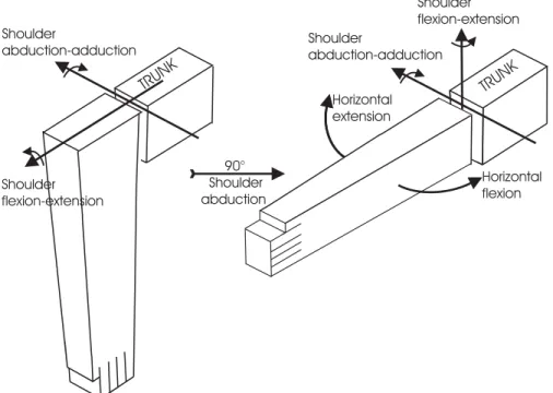
This physiological approach to kinematic robot-arm struc-tures is suggested by the development of humanoid robots in which arms have a first horizontal axis performing flexion–extension or abduction–adduction movements in-stead of the central vertical axis of industrial robot-arms. For example, the arms of the Honda humanoid robots P2, P3 or Asimo have a 7R structure for which the first axis performs a shoulder flexion–extension (Hirai et al. 1998; http://world.honda.com/ASIMO/). The choice for the first axis—whether shoulder flexion–extension or shoulder abduction–adduction—is free. However, in order to be in agreement with the joint physiology definition of the horizon-tal flexion–extension (Kapandji 1982), it was decided to con-sider the shoulder abduction–adduction first. Consequently, if abduction is zero, shoulder flexion–extension is performed on a vertical plane, and on a horizontal plane if abduction is 90◦, as illustrated in Figure 2.
Finally, the following sequence was considered for the shoulder: abduction–adduction, flexion–extension, and external–internal rotation. For reasons of symmetry, first abduction–adduction and secondly flexion–extension were also considered for the wrist. Figure 3 shows this 7R struc-ture, where it can be noted that the wrist corresponds in me-chanical terms to a roll–pitch–yaw wrist type instead of the roll–pitch–roll wrist type of usual 7R anthropomorphic robot-arms. Figure 3(a) specifies the association of the rotation axis
Fig. 1. Correspondence between roll–pitch–yaw mechanical notation and physiological joint motion notation. (a) Classical marine metaphor of roll–pitch–yaw motion of a mobile link seen as a boat sailing along a given reference Z-axis. (b) Physiological joint motions of a mobile link jointed to a given link: external–internal rotation corresponds to a roll motion, flexion–extension to a pitch motion and abduction–adduction to a yaw motion (note that the choice for a positive sense is dependent on link physiology).
TRUNK TRUNK Horizontal flexion Horizontal extension Shoulder flexion-extension Shoulder abduction-adduction 90° Shoulder abduction Shoulder abduction-adduction Shoulder flexion-extension
Fig. 2. Argument for considering shoulder abduction–adduction first in the kinematic chain so as to be in agreement with the physiological definition of the shoulder horizontal flexion–extension, as considered in classical joint physiology treatises (Kapandji 1982).
Shoulder abduction-adduction (SA)
Shoulder
flexion-extension (SF) Arm external-internal rotation (AR)
TRUNK
Elbow flexion-extension (EF) Wrist abduction-adduction (WA) Wrist flexion-extension (WF) Prono-supination (PS)1
2
4
3
6
5
7
180 SA 30TRUNK
180 SF 50 80 AR 110 145 EF 0 45 WA 45 85 PS 85 85 WF 853
2
1
4
5
6
7
(a) (b)Fig. 3. Fundamental 7R anthropomorphic structure defined in the joint physiology terminology: (a) zero-anatomical position; (b) considered zero-robot position (indicated joint ranges correspond to anatomical given by Kapandji 1982).
with the bodily structure considered in the form of the three main segments: arm, forearm, and hand, in the so-called zero-anatomical position where the arm falls along the body with the palm open to the front. The positive sense of every joint axis was chosen to correspond to an “opening” motion of the upper limb, as specified in Table 1. Because the wrist is fully stretched in the zero-anatomical position, a zero-robot posi-tion is considered in which the wrist joints are in a medium configuration, as illustrated in Figure 3(b). The robot hand in use is a simple two-finger grip mimicking the thumb in oppo-sition to the set of other fingers. Before dealing with the me-chanical design of the anthropomorphic robot-arm, the main properties of the McKibben muscle actuators are described, which are to motorize this robot-arm.
3. Naturally Compliant Artificial Muscle
Actuators
3.1. Fundamental Model of Artificial Muscle
Skeletal muscles are characterized by a contraction force de-pending on the length of the muscle. During physiological contraction, muscle tension decreases in the same way as mus-cle length. Consequently, the skeletal musmus-cle behaves like a spring for which the stiffness depends on the nervous control of the muscle. Although the nervous system can vary the mus-cle force in a complex manner, either by recruitment of motor units or modulation of the firing rate of motor neurons (Ghez 1991), the following fundamental linear model of the skeletal
Table 1. Choice of Positive Sense of the Physiological-Type Arm Motions
Rotation
Flexion–extension Abduction–adduction Pronosupination
Positive sense Flexion Abduction External or pronation
Negative sense Extension Adduction Internal or supination
muscle static force can be considered: !
F=ufmax(1−
ε εmax
),0≤ ε ≤ εmaxand 0≤ u ≤ umax
ε= (l0− l)/l0.
(1) Here, u designates the value of the nervous control on a [0, umax] range, ε is the contraction ratio of muscle length l with
regard to the resting muscle length l0in a [0, εmax] range, and
fmaxis the maximum force per control unit. From eq. (1), the
muscle stiffness equation is obtained: Fr = −u
fmax
εmax
δε. (2)
This means that the muscle, deviating from its equilibrium position of a δε, returns to this position due to a restoring force Fr, as illustrated in Figure 4.
This model can be used as a reference model for any type of artificial muscle which is defined as a spring-like device for which the control variable is proportional to its stiffness. A competitive approach defines the notion of artificial mus-cle from the skeletal musmus-cle in Hill’s model, which favors a tension–velocity relationship (Klute, Czerniecki, and Han-naford 1999, 2002). We preferred a tension-length model so as to highlight the “natural compliance” of the artificial mus-cle actuator resulting from the musmus-cle’s spring-like behav-ior. On the other hand, as opposed to a Hill-based model, using a spring-type model more easily distinguishes the stiff-ness component from the viscous-type component, which will be considered later. Any artificial muscle must be naturally damped but, especially in the case of fluid artificial muscles, this natural damping depends on the materials used to build the artificial muscle (inner tube, textile braid) as well as the servo-valve supplying the muscle. In particular, the McK-ibben muscle, as a system where input is the control pressure and output the muscle length, can appear as poorly damped (Klute, Czerniecki, and Hannaford 2002). This means that no damping would occur in response to a physical pressure step. However, in practice, muscle pressure is generated by using a specific pneumatic or hydraulic servo-valve contributing, in conjunction with a judicious choice of textile braid, to natu-rally damping dynamic muscle behavior (see Figure 5(d)).
3.2. McKibben Artificial Muscle
In the fundamental length-tension eq. (1) model, no hypothe-sis is made on the nature of control variable u. The notion of
Fig. 4. Linear model of muscle static force production.
the artificial muscle is consequently very free concerning the physical principle that produces the contraction force. How-ever, in previous studies we have shown how beneficial it is to use air-pressurized inner tubes surrounded by braided shell to design artificial muscles adapted to robot-arms. The so-called McKibben artificial muscle today appears as one of the most promising artificial muscles, as proved by the numerous papers devoted to it. Basically, when the McKibben muscle inner tube is under a pressure P , the double-helix braided shell surrounding it transforms the circumferential stress of the inner tube into an axial contraction force F , which can be expressed in the fundamental generator force model (Tondu and Lopez 2000): ! F (ε, P )= (πr2 0)P[a(1 − kε)2− b], 0 ≤ ε ≤ εmax ε= (l0− l)/l0, a= 3/ tan2(α0), b= 1/ sin2(α0). (3) Instead of contraction ratio ε, an equivalent model consid-ers the current braid angle (i.e., the angle between the muscle axis and one strand of the textile weave) as the muscle char-acteristic contraction variable (Schulte 1961; Chou and Han-naford 1996; Davis et al. 2003). It seems to us preferable to favor contraction ratio ε (or the current muscle length) as an output variable in order to more easily derive the antagonis-tic muscle actuator model. The proposed model characterizes McKibben muscle of current length l by its inner tube, ini-tially cylindrical, of initial length l0 and of initial radius r0,
and by its textile weave of initial braid angle α0, which is
de-rived from the data of our cotton braid supplier.1 Note that
the use of cotton gives a natural softness to the braid, which helps to completely cover the inner tube with the braid at rest state. In these conditions, McKibben artificial muscle is clearly geometrically characterized in its non-stretching rest state by the three parameters l0, r0, and α0. Conversely, the
use of plastic-type fibers, as considered by other researchers, creates a braid stiffness which “opens” the braid and makes it stretchable from its rest state to the state in which the braid completely covers the inner tube. There results a real diffi-culty in equating muscle initial state l0, r0 with initial braid
angle α0as considered here.
However, the purely cylindrical model with three parame-ters is too simple to express the artificial muscle behavior as a force generator in a satisfactory manner. This is why we have introduced a correction parameter k. Factor k is an empirical factor, experimentally derived, expressing both a bound effect (muscle does not maintain its cylindrical shape at end prox-imity when it contracts) and the non-integral transmission of pressure force into the muscle weave. Modeling muscle enve-lope evolution by finite elements, as envisaged by the Wash-ington Biorobotics Laboratory (http://brl.ee.washWash-ington.edu), is a promising way to theoretically model the bound effects, but might not be sufficient to fully explain the high depen-dence between control pressure and real maximum contrac-tion ratio. Faced with this complexity, we preferred to preserve a simple shape of the muscle force generator model by intro-ducing the empirical parameter k, which can be estimated as a constant or as a function dependent on pressure P .
Compared to the general artificial muscle eq. (1) model, the McKibben muscle tension-length model appears not to be as exactly linear as eq. (3) expresses it. It does however at-tain the desired artificial muscle nature by generating stiffness globally proportional to the control pressure. We have devel-oped our own artificial McKibben muscles and tested them on the experimental setup, which are used to record muscle pa-rameters during isometric and isotonic contraction as defined by physiology (Ghez 1991). Figure 5(a) shows an isometric contraction for a muscle of 120 mm initial length, 7 mm ini-tial radius, and a 23◦ initial braid angle, aimed at motorizing
the wrist of our 7-DoF prototype. Figure 5(b) shows isomet-ric contraction for a muscle of 230 mm initial length, 12 mm initial radius, and a 17◦initial braid angle, aimed at
motoriz-ing the robot-arm shoulder. The resultmotoriz-ing experimental static tension-length at constant pressure emphasizes the ability of McKibben muscle to develop high maximum force in relation to its own weight and volume. Under 5 bars, the considered muscle can develop a maximum force greater than 5000 N for
1. The application of textile technology classical formulae indeed gives
tan(α0) = π(Dint − 2d)/p, where Dint is the internal diameter of the
braid, d is the diameter of the thread, and p is the braid pitch that can be determined from p= ns/2nm(in cm), where nsis the number of spindles
and nmis the number of meshes by centimetre.
a weight of about 100 g and a maximum volume of about 500 cm3. Note that the McKibben muscle maximum force can be
dimensioned by imposing the value either of the initial braid angle or of the initial muscle radius. However, as is clearly shown by eq. (3), maximum muscle force is very sensitive to a small variation in the initial braid angle. Consequently, we preferred this parameter to define the set of muscles mo-torizing the robot, thus obtaining a wide range of maximum contractile force. It is important however to emphasize that the smaller the initial braid angle, the more the muscle radius increases during contraction, which thus requires an adequate choice of rubber able to tolerate the corresponding elongation. However, the power of the McKibben muscle is limited by its pneumatic nature and particularly by the dynamic be-havior of the servo-valve feeding it with pressurized air. The contraction of the McKibben muscle does indeed go with air consumption all the more higher as the initial braid angle is low. Considering a purely cylindrical model of the McK-ibben muscle (i.e., r = (r0/sin(α0))
√
1− cos2(α
0)(1− ε)2;
Tondu 1995) the following approached expression of the cur-rent muscle volume V (ε) can be derived
V (ε)= V0(1− ε)(1 − cos2(α0)(1− ε)2)/sin2(α0)
where V0 is the muscle initial volume (πr02l0). The result is
that the ratio between the current muscle volume and its initial volume has a maximum value corresponding to the theoreti-cal maximum contraction ratio2 ε
max = 1 − (1/
√
3 cos(α0))
and equal to (2/3√3 cos(α0)sin2(α0)). The classic formula
of perfect gases P V = (m/M)RT (where P is pressure, V is volume, m is mass, M is molar mass, R is gas con-stant, and T is temperature) can be applied to determine air consumption %m between the zero-contraction state and the maximum contraction state for a %P pressure variation. We obtain %m = (2/3√3 cos α0sin2α0)(V0M/RT )%P. In the
case of the biggest shoulder muscles of our 7R robot (joint 2: l0 = 230 mm, r0 = 12 mm, α0 = 17◦) the muscle volume
initially equal to about 104 cm3 can theoretically increase
until about 470 cm3, which for a %P =5 bar pressure
varia-tion corresponds to an air consumpvaria-tion of 2.85 g, a little less however in practice. In the case of the servo-valves feeding the muscles of our robot-prototype—Samson I/P converters (Samson Corporation, Frankfurt, Electropneumatic Converter I/P 5288), generally considered to be rapid in their 0–5 bar output pressure range—a relatively slow pressure rise results, as shown in the example in Figure 5(c), corresponding to an isotonic contraction of the above-mentioned shoulder muscle picking up a 15 kg mass in response to a 5 bar numerical step. Corresponding muscle length evolution is given in Fig-ure 5(d). During contraction, maximum muscle power can be estimated at 75 W, which appears as a relatively weak value given the maximum muscle force (in comparison, the skeletal
2. This result is consistent with the fact that the McKibben muscle cannot contract without increasing its volume (Tondu and Lopez 1995).
(a) (b)
(c) (d)
Fig. 5. Isometric and isotonic recordings of McKibben muscle responses: (a) isometric force response for a 7R robot wrist muscle; (b) isometric force response for a 7R robot shoulder muscle; (c) and (d) isotonic response in pressure, force, and position x = (l0− l)/l0for the robot shoulder muscle corresponding to (b) isometric response.
muscle develops a maximum power of about 250 W; Bouisset 1987). The increasing of the McKibben muscle power neces-sitates, in consequence, the increasing of the bandwidth of the servo-valves feeding it.3Interesting proposals have been
made with this end in view (Davis et al. 2003). It is important however that the sizes of the valves, just as the sizes of the air pipes, do not become out of proportion to the muscle size.
The low bandwidth of the McKibben muscle corresponds to moderate response times. The McKibben muscle response
3. We have analyzed elsewhere the bandwidth of our I/P converters (Boitier 1996). Its value appears to be independent of the mean working pressure if it is greater than 2 bars but, naturally, depends on output volume; it can be estimated at 5 Hz for a 75 cm3volume, at 1 Hz for a 300 cm3volume, and at 0.5 Hz for an 800 cm3volume. Consequently, the bandwidth of our robot muscles varies as a function of the muscle size between about 1 and 4 Hz.
time depends on multiple factors (e.g., initial muscle volume, controlled pressure variation, and load), but is generally be-tween 0.2 and 1 s (Figure 5(d) gives a typical result for the strongest muscles of our robot which are also the slowest) when the skeletal muscle contracts between 10 and 300 ms (Boff and Lincoln 1988). This relative slowness of the artifi-cial muscle contraction could appear as a real handicap for the development of robot-arms actuated with McKibben artificial muscles. However, it is important to note that artificial muscle robots aim at performing tasks at “human” speed and accu-racy, and today’s dynamic McKibben muscle performances are relatively close to those of their human skeletal equiv-alents. However, researchers have become interested in the abilities of the human arm to perform high-frequency tasks such as drum rolls at a 30 Hz frequency despite the relative
slow response of the neuromuscular system (Hajian, Sanchez, and Howe 1997). By testing their hypothesis on McKibben muscles, they have shown how the modulation of muscle pas-sive impedance can explain this paradox. Such an approach could be applied to the control of McKibben artificial muscle robot actuators.
Furthermore, all researchers who have worked on braided muscles have emphasized the difficulty of obtaining an ac-curate model of muscle contraction (see, for example, Klute 2002). This difficulty is mainly due to the structure itself of the artificial muscle consisting of soft materials whose inter-actions are complex, and also to the necessity of separating the specific muscle dynamics from the servo-valve dynamics. In a general way, McKibben muscle dynamic force can be written as
Fdyn= F − Felast ic− Ff rict ion, (4)
where F is the static force generated by the muscle as ex-pressed in eq. (3), Felast icis an elastic force component
asso-ciated with the inner tube dynamic behavior, and Ff rict ion is
a dry and kinetic complex friction force component associ-ated with the braid dynamic behavior. Friction forces seem to be particularly important in explaining the specific actua-tor hysteresis (Tondu and Lopez 2000). In comparison with classical actuators, the dynamic complexity of the McKibben muscle appears to be the price to be paid for the natural soft-ness conferred to the robot by the artificial muscle. It implies an increased but non-insuperable control difficulty of the ar-tificial muscle antagonistic actuator.
3.3. Antagonistic McKibben Artificial Muscle Actuator
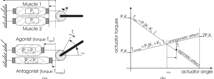
Based on the model of the natural biceps–triceps system, two artificial muscles can be set into antagonism for defining a revolute actuator according to the basic scheme of Figure 6(a). The working principle of the actuator is as follows. The two identical muscles are initially contracted of a ratio ε0= εmax/2
under a pressure of P0 = Pmax/2, where Pmax is generally
chosen equal to 5 or 6 bar and εmax is generally equal to a
value between 0.1 and 0.15, due to a mean practical maximum contraction range of between 20% and 30% (see Figures 5(a) and (b)). From this initial situation, each muscle can contract or lengthen by ε02. If the actuator drive is performed by a
chain wheel of radius R, the motor torque generated by the actuator is given by
T = R[F1(ε1, P1)− F2(ε2, P2)]. (5)
In this expression, F1designates the force produced by muscle
1 (defined as that producing positive actuator rotation motion) inflated at pressure P1 and contracted of a ratio ε1 = ε0−
(Rθ/ l0), and F2designates the force produced by muscle 2,
inflated at pressure P2 and contracted by a ratio ε2 = ε0−
(Rθ/ l0). According to whether pressure P1> P0or P2 > P0,
F1 or F2 is an agonistic-type force, the force produced by
the other muscle is an antagonistic-type force. From the force generator model of eq. (3), with a k constant typically between 1.25 and 1.35, the following expression of the static motor torque can be derived:
T = K1(P1− P2)− K2(P1+ P2)θ , with K1= (πr02)R[a(1 − kε0)2− b] K2 = (πr02)R2a(1− kε0)kR/ l0. (6)
This model is particularly interesting as it shows how the antagonistic McKibben artificial muscle actuator performs the principle of the equilibrium point found in physiology (Bizzi et al. 1992).According to this principle, the static motor torque can be divided into two effects—an agonistic effect Tagoand
an antagonistic effect Tant ago—as follows
T = Tago− Tant ago, with
&
Tago= Pago(K1− K2|θ|)
Tant ago= Pant ago(K1+ K2|θ|) ,
(7) where (Pago, Pant ago)is equal to (P1, P2)if θ ≥ 0 and to (P2,
P1)if θ ≤ 0.
Equilibrium point θequis defined by equality Tago= Tant ago,
which leads to the following expression of θequ:
θequ=
K1(P1− P2)
K2(P1+ P2)
, (8)
as Figure 6(b) illustrates. When the actuator deviates from the equilibrium point of value δθ, it returns to it by means of a restoring torque
Tr = −K2(P1+ P2)δθ, (9)
which expresses the actuator stiffness theoretically estimated by the term K2(P1+P2). Generally speaking, the antagonistic
McKibben muscle actuator is a system with a double input (P1,
P2)and a single output θ, for which the control would need a
multivariable approach. However, it is possible to control the actuator as a single input–single output by defining agonistic and antagonistic muscle controls symmetrically as follows: P1 = P0 + %P , P2 = P0 − %P . Consequently, the static
motor torque expression becomes a linear function of the input variable %P and the output variable θ:
T = k1%P − k2θ, where k1 = 2K1, k2= 2K2P0. (10) It is important, however, to note that the muscle volume does not change linearly with its contraction ratio. As a conse-quence, the air consumption of the two antagonistic muscles is not symmetrical.4The result is a slight delay in the buildup
4. From the cylindrical model of the McKibben muscle, it can indeed be derived in accordance with the equations given in Section 3.2 that the
mus-cle volume increases during contraction according to a slope dV (ε)/dε =
P02 axis equ
P >P
1 0P <P
2 0P
0P
0Muscle 1
Muscle 2
Agonist (
torqueT )
agoAntagonist (
torqueT
antago)
T
ractuator
torques
actuator angle
agonistic effect antagonistic effect equT
rT
=P
(K
-K
)
ago 1 1 2T
=P (K
+K
)
antago 2 1 2P K
1 1P K
2 12P K
2 1 (a) (b)Fig. 6. Antagonistic McKibben muscle actuator: (a) functioning principle; (b) application of the equilibrium point principle to the antagonistic muscle actuator (illustrated in the case of positive θ actuator angle).
of the desired pressure in the two antagonistic muscles, all the higher as the two muscles have different contraction ra-tios, i.e., actuator angle θ is close to its extreme values.
In the equilibrium position, the actuator behaves like a spi-ral spring whose stiffness is now independent of θ and equal to k2. This stiffness is particularly adapted to human contact:
for example, the elbow flexion–extension joint 4 of our 7R robot is motorized by muscles of parameters l0= 195 mm, r0
= 8.5 mm, α0 = 19◦, k = 1.25, with a chain wheel of radius
R = 14.5 mm and P0 = 2.5 bar, ε0 = 0.1, leading to an
esti-mated stiffness of about 15 N.m.rd−1near to values given by
joint physiology (Boff and Lincoln 1988). The term “natural compliance” has been given to this joint compliance, which has the same nature as that of the joints of our skeleton. How-ever, this natural compliance would be of no practical use if the actuator were not naturally damped. As previously em-phasized, this natural damping of the actuator is due to par-ticularly complex elastic and friction phenomena specific to the muscle components as it is to the servo-valve dynamic behavior. Despite this complexity (and apart from hysteresis behavior) the dynamic expression of the motor torque can be satisfactorily approached by a linear expression as follows
Tdyn= a1%P − a2θ− a3˙θ, (11)
leading to a second-order linear model of the actuator that drives a constant inertial load. Defined in this way, the McK-ibben artificial muscle actuator is an open-loop stable system. In consequence, the system is easily identifiable and the cor-responding identified model can be used as a forward action of a linear or non-linear corrector (Tondu and Lopez 2000).
On the one hand, the antagonistic McKibben artificial mus-cle actuator offers static performances in maximum force–
muscle weight and maximum force–muscle volume ratios well adapted to the motorization of human-size robot-arms. It also offers dynamic performances in response time, damping and compliance relatively well adapted to generating human-like motions, and, moreover, improvable. However, the maxi-mal contraction that varies between 15% and 40%, depending on muscle parameters and control pressure, is a major disad-vantage of the McKibben muscle. In comparison, the skeletal muscle contracts only 30% at rest, but in vivo the muscles of vertebrates are stretched by about 10–20% of their length at rest (Boff and Lincoln 1988). In vivo skeletal muscle can then contract by 40–50%. This structural limitation specific to McKibben muscles imposes, for a desired joint range, the obligation to look for an adequate compromise between mus-cle length and pulley radius with the possible help of a speed increaser, as will be seen in Section 5. Unfortunately, nat-ural muscle compliance implies that motor torque is highly dependent on the joint variable. An artificial muscle robot is consequently highly dependent on gravity, unlike classical industrial robots, which are free from any gravity effect due to their speed reducers. The design of our anthropomorphic artificial muscle robot-arm aims at taking advantages of the McKibben muscle actuator properties.
4. Design of the 7R Anthropomorphic
Robot-arm
The classic, and essentially electric, revolute actuators of industrial robotics are characterized as to bulk by a com-pact structure globally symmetrical around the actuator rota-tion axis. In comparison, the antagonistic McKibben muscle
actuator shows very different bulk mechanical characteristics, as follows.
1. First, muscle length is a specific bulk factor because the actuator joint range directly depends on it; this fac-tor is all the more significant as the muscle maximum contraction ratio is limited. Like the human muscular-skeletal system, it is possible however to integrate the artificial muscles along the links of the robotized structure.
2. Secondly, the rotation axis is perpendicular to the actu-ator two-muscle “plane” and located at an edge of the pair of muscles. In consequence, the artificial muscle actuator does not show this axial symmetry peculiar to most revolute actuators.
As a consequence, the design of a robot actuated with ar-tificial muscles must be adapted to the nonclassical character of this revolute actuator, in order to find the right compro-mise between acceptable dimensions of the robot and desired dynamic performances. The goal of our study consisted of designing a robot-arm where the arm and forearm segments would have lengths similar to those given by human biometry, and the joint ranges are defined according to the 7-DoF model of the human arm presented in Section 2, while minimizing the total weight of the robot. This minimization combined with the joint natural compliance is indeed an essential element for the safe functioning of the robot in a human environment.
4.1. Dimensioning of the McKibben Artificial Muscle Actuator
If we consider, as illustrated in Figure 6(a), that each muscle is initially contracted by ε0the actuator joint range is given by
θrange= [−ε0l0/R, + ε0l0/R] (rd). (12)
Furthermore, in the functioning conditions given in Sec-tion 3.3, it appears that the maximum torque in absolute value is generated for a variable control %P equal to P0 and for
an angular variable θ equal in absolute value to|ε0l0/R|.
De-rived from eq. (10), the following expression of the maximum torque results
Tmax= k1P0+ k2(ε0l0/R),
which can be expressed in the following form by using eq. (6)5
Tmax= 2(πr02)R[a(1 − k 2ε2
0)− b]P0. (13)
Comparing eqs. (12) and (13), it appears that, if joint range and maximum torque naturally depend both on muscle pa-rameters and driving pulley radius, the joint range does not
5. This result corrects the incomplete analysis of maximum torque generated by the McKibben muscle actuator we have previously developed (Tondu and Lopez 2000).
depend on α0and r0 Consequently, these latter two
parame-ters can be specifically used for the dimensioning of the max-imum torque. It is also important to note that the joint range directly depends on initial muscle length l0, but a
lengthen-ing of the muscles unfortunately increases the bulkiness of corresponding mechanical parts supporting the muscles. If pulley radius R plays the classic role of increasing or de-creasing joint range and maximum torque in an inverse ratio, initial muscle contraction ε0 plays a specific role this study
would like to emphasize. Its value has a weak influence on the maximum torque and a large influence on the joint range. As previously stated, a typical range for ε0 is 0.1–0.15 but
it can be interesting to adjust this value accurately, either to increase the maximum joint range by choosing ε0 near the
estimated maximum value, or to use ε0as a factor for tuning
the corresponding joint mechanical stop. This approach will be used in our robot prototype.
Furthermore, the current actuator torque appears to depend on the angular variable generated by the actuator, in analogy with human gestures. For the robot actuated with artificial muscles, a load manipulation results fundamentally different from that of industrial robots, which is generally performed at constant torque. The consequence of this joint dependence of the actuator torque will be analyzed in Section 5 when the robot moves against gravity.
4.2. Mechanical Arm Design Based on the Use of CAD Modeling6
Mechanical arm design aims to develop technological solu-tions adapted to the artificial muscle actuator, which combines arm compactness globally equivalent to that of the human arm, with joint ranges approaching those of the human arm, as indicated in Figure 3(b).
In comparison with Bridgestone soft-arms and derived robots, the relatively advanced anthropomorphic character of our robot-arm has led us to develop original solutions for the shoulder and the wrist design in order to achieve specific abduction–adduction and flexion–extension motions. The θ1
and θ2 shoulder joints impose the most difficult muscle
di-mension constraints because the corresponding joint actuators have to develop the highest motor torques for driving the arm against gravity. Making these two joints independent is also a major difficulty, as already emphasized by Tsagarakis and Caldwell (2003) whose McKibben muscle exoskeleton shows a shoulder flexion–extension and abduction–adduction depen-dence. The original solution we have considered to obtain this independence is based on the possibility of contracting the two ends of the McKibben muscle simultaneously. Figure 7 illustrates the joint 1 and joint 2 corresponding mechanical system. The joint 1 muscle pair is fixed to the robot frame. It
6. Details of the mechanical design developed on I-DEA CAD software are not given within the framework of this paper. A more specifically mechanical paper presenting the design of our anthropomorphic arm is being prepared.
(a) (b)
Fig. 7. Mechanical design of the robot shoulder: (a) general diagram illustrating the independence principle for joint 1 and joint 2 motions; (b) photograph of the two muscle pairs driving the robot shoulder joints.
controls a pair of spur gears (ϕ and κ), driven by the actuator pulley λ, which amplifies the actuator angular motion in a 1.5 ratio. In opposition, joint 2 muscles can contract their two ends simultaneously. Joint 2 moves according to a differential principle performed by two bevel gears, functioning in oppo-sition by means of a back pulley mechanism. When joint 2 muscles are controlled, they both act on pulleys µ and ν gen-erating corresponding opposite angular displacements (−θ& 2
and+θ&
2). Consequently, joint 2 can move independently of
joint 1, and when joint 2 does not move, the joint 2 driving system acts as an extensible tie that prevents pulleys µ and ν from rotating. As in the case of joint 1, the joint 2 bevel gear system amplifies the actuator angular motion in a 1.5 ratio. It is however important to note that if the considered mechanical system of joint 2 can generate a torque equivalent to that which would be obtained with a fixed end, the cor-responding joint range is divided by 2 since it corresponds to twice the muscle contraction when one end is fixed. This joint range deficiency could be compensated by doubling the muscle length but would lead to unduly increasing the robot frame length. Consequently, joint 2 muscles are very slightly oversized compared to joint 1 muscles with a corresponding ε0tuned to its maximum value. As mentioned in Table 2, we
can therefore hope to expect a 180◦joint 1 range and a 100◦
joint 2 range with maximum torques greater than 60 N m. Wrist flexion–extension and abduction–adduction are not so severely constrained in torque and joint range perfor-mances. Joint 6 is directly driven by its muscle pair as il-lustrated in Figure 8(a), and joint 7 is independently directly driven by means of a swing-bar of half length L7size which
plays the role of the pulley radius R of other joint actuators, as illustrated in Figures 8(b) and (c). This mechanical solution
gives the wrist a compactness in accordance with the desired human-like robot dimensions.
Table 2 synthesizes the set of muscles and transmission system characteristics. They were selected so as to gener-ate anatomically desired joint ranges with associgener-ated max-imum possible torque, while maintaining robot-arm dimen-sions similar to those of human arms. Note that the given value of “peak force” can be estimated from torque eq. (13) (with a typical k equal to 1.25) divided by the ratio mV. Figure 9
gives the resulting prototype. Its arm, in the anatomical sense, has a 351 mm length between axes, and its forearm a 307 mm length between axes. The lateral frame supporting the shoul-der muscles is 350 mm wide. The hand is a simple two-finger grip actuated by a double-effect pneumatic cylinder. Figure 10 shows the current development of the robot with its muscle ac-tuators. The total weight of the robot’s mobile parts including muscles and chains is about 6 kg and the robot’s total weight with its shoulder (fixed base) is about 10 kg. The weight of the pneumatic interface, which is essentially the weight of the 14 I/P converters supplying the muscles as the I/P con-verter supplying the robot tool-plate, is about 10 kg. These converters have been set in a lateral box attached to the robot frame. The size of used I/P converters is a bulk factor (each I/P converter has a volume more or less equal to 500 cm3)but
commercialized smaller I/P converters could be expected in the future. The supply requirement is essentially pneumatic; the electrical supply requirement is limited to the supply of the I/P converters, sensors and a robot controller. The robot pneumatic supply of the arm is ensured by the University’s air-supply system (6 bar). This supply could be attached to the robot under the form of a high-pressure gas tank, although the energy range of the robot is limited by the high air
consump-(a) (b) (c)
Fig. 8. Mechanical design of the robot wrist: (a) photograph of the robot wrist showing joint 6 direct drive; (b) diagram of joint 7 transmission by swing-bar; (c) photograph of joint 7 transmission.
Table 2. Actuators Characteristics
Pulley-Chain Transmission
Muscle System System Estimated
Characteristics Characteristics Characteristics Estimated Peak
Joint l0 r0 α0 R Joint Range Torque
Number (mm) (mm) (deg) ε0 (mm) Mode mv (deg) (N.m)
1 195 12 17 0.11 20.5 Cylindrical gear 1.5 [0◦–180◦] 61 2 230 12 17 0.15 23 Double bevel gear in opposition 1.5 [0◦–100◦] 67 3 140 8.5 20 0.15 18 Bevel gear 1.5 [–100◦,+100◦] 18 4 195 8.5 19 0.10 14.5 Direct drive 1 [0◦,+150◦] 25 5 120 7 23 0.08 12.5 Bevel gear 2 [–90◦,+90◦] 5 6 120 7 23 0.07 12.5 Direct drive 1 [–35◦,+35] 10 7 120 7 23 0.11 17.5 Direct drive by cross-bar 1 [–45◦,+45◦] 13
tion of McKibben muscles, as mentioned earlier. However, the latter could be reduced by a pre-filling of the artificial muscle (Davis et al. 2003) or by a reprocessing of the pressurized air between the two actuator muscles.
5. Experimental Validation of the Prototype
The robot was tested in a teleoperation mode by means of two three-axis joysticks that control joints 1, 2, 4 and joints 5, 6, 7, and a swing bar controlling joint 3. Joint position can be controlled in open loop since the antagonistic muscle actua-tor is stable in open loop or in closed loop through a simple linear PID controller; the problem of actuator control is not discussed in this paper, as it was dealt with in our extensive paper (Tondu and Lopez 2000) and discussed elsewhere (Hes-selroth et al. 1994; Van der Smagt, Groen, and Schulten 1996;Cai and Yamaura 1997). The teleoperation of the robot has a double goal: testing real joint ranges especially against grav-ity, which is a fundamental character for humanoid robotics, and testing effective robot compliance when tasks involving a contact of the robot with its environment are performed.
5.1. Test of Robot Joint Ranges Against Gravity
It is well known that the joints of a robot-manipulator are in-fluenced by dynamic effects from other joints and from the static effect of gravity. In classical industrial robots, these effects are generally diminished by using high ratio speed re-ducers associated with high-speed rotating actuators. Such a strategy is impossible in the case of our robot because the natural compliance of the artificial muscle will be lost. Direct driving or driving by angle multiplier of moderate ratio are
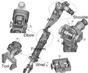
Fig. 9. General diagram of the main parts of the anthropomorphic robot-arm mechanical design.
(a) (b)
(c)
Fig. 10. Photographs of the 7R anthropomorphic arm: (a) lateral view photograph; (b) front view photograph; (c) rear view photograph.
the only adapted driving modes. The first consequence is the dynamic non-linear behavior of the artificial muscle actuator, which must be taken into account by the robot (Tondu and Lopez 2000). It must also be noted, however, that the field of applications to be performed by this kind of soft robot-arm necessitates generally moderate speeds and accelerations. The second consequence that we wish to study here is the static be-havior of robot against gravity. This bebe-havior is submitted to the dependence of the actuator and gravity torques on actuator angle, as Figure 11 illustrates. Using the actuator static model of eq. (10), including a speed increaser of ratio mV, and
no-tations of Figure 11(a), the following equation expressing the total joint torque submitted to the gravity effect is obtained:
Tjoint= (1/mV)k1%P − (1/mV)2k2θjoint− mgl cos θjoint.
(14) A typical simulation of joint eq. (14) in a [–90◦,+90◦] angu-lar range is given in Figure 11(b) assuming a %P constant equal to the maximum value (P0/2). It highlights the fact that
the total torque can take a minimum value for a joint angle between 0◦and 90◦. If this minimum value is negative, due,
for example, to a load at the robot end-effector, the maximum corresponding joint angle will be equal to the joint value corre-sponding to a total torque equal to zero. The flexion–extension and abduction–adduction shoulder joints are particularly sen-sitive to this situation because their actuator could have to face maximum resistive gravity torque when the forearm is in full extension. When a large joint range is desired, associated with the need for high torques, as required by the shoulder joints, it is possible to associate power muscles with a speed increaser of moderate ratio. Figure 11(c) gives the simulation result ob-tained with the joint 1 parameters of the 7R robot moving in full forearm extension. Without any load, it appears clearly that the full 180◦desired joint range is obtained. This is also the case if the robot tool carries a 1 kg load. However, if the end-effector robot load becomes equal to 2 kg, the effective joint range is limited to about 90◦due to the typical joint
re-sponse against gravity. Such simulation illustrates a typical property of robot limbs actuated with artificial muscles: joint ranges are highly gravity-dependent.
Figure 12 shows the variations in movement of the seven joints of the robot controlled at very slow speed to eliminate dynamic effects. Joint 1 and joint 2 motions were recorded at full-arm extension. The theoretical estimated full angular range was checked for every joint and the effect of carrying loads tested. By comparison with anatomical values, all joint ranges can be performed by our anthropomorphic robot-arm except for joint 2, for which current range at full forearm ex-tension is limited to about [0˚, 100◦]. Such a phenomenon
highlights the difficulty of designing compact and powerful shoulders performing both flexion–extension and abduction– adduction. For other mechanical reasons, Honda humanoid P3 is unable to lift its extended arms higher than the horizontal and robot Asimo limits its maximum shoulder “joint
mount-ing” to about 110◦, due to the overlapping of the two shoulder freedoms of movement, as mentioned in the available techni-cal data (http://world.honda.com/ASIMO/). The paradoxitechni-cal difficulty of lifting a 6 kg anthropomorphic robot-arm actuated with artificial shoulder artificial muscles generating a maxi-mum force close to 5000 N highlights a double specificity of human body mobility. First, human body links are relatively light since the upper limb weighs only about 3.6 kg (Winter 1969). Only the use of composite materials would result in our robot-arm prototype being lightened to this anatomical value. Secondly, the control of natural motions is based on muscular synergies. Let us recall that the human shoulder is governed by about 10 main muscles, for which the control sequence depends on the arm elevation angle.
5.2. Soft Task Test
To test its ability to perform soft grasping manipulation tasks, we teleoperated the robot-arm in joint space conditions to grasp a glass and put it back on to a hard surface, as Figure 13 illustrates. When the glass is on the table it is still possible, even in joint space control condition, to make it slide on the table without breaking it. Such an academic task stresses the surprising skills of artificial muscle actuators to imitate the human touch.
The compliance of the robot-tip is not controlled in this experiment but it is important to note that it is possible to define a stiffness matrix in the Cartesian space. If we note q as the vector of the robot joint variables, Trthe vector of joint
restoring torques, x the robot-tip location vector and Fr the
corresponding restoring force–torque vector in the Cartesian space, the application of the virtual works theorem gives
δxT.F
r= δqT.Tr.
By considering the Jacobian matrix of the robot J and its pseudo-inverse J+, we could write
Fr= −Kδx with K= (J+)TK
qJ+
(15) where Kq represents the joint stiffness matrix and K is the
corresponding Cartesian stiffness matrix. Kqis a diagonal
ma-trix, the terms of which have, from eq. (9), the general form K2(P1+ P2)reducing to k2 in case of symmetrical pressure
control, if necessary multiplied by a transmission term such as (1/mV)2. In the framework of our paper, eq. (15) expresses
a simple fact: if we motorize a robot-arm kinematically anal-ogous to the human arm with actuators whose stiffnesses are similar to those of corresponding human joints, the compli-ance at the tip of the robot-arm will be similar to that of our arm. Further experiments will aim to quantify the ability of such 7R anthropomorphic robot-arms actuated with artificial muscles, to reproduce natural human touch in world space.
maximum gravity effect minimum actuator
torque-null gravity effect
+90°
+
-90°
maximum actuator torque-null gravity effect
speed increaser of ratio m
mg
l
joint=0°
joint v (a) (b) (c)Fig. 11. Theoretical analysis of the behavior of the antagonistic artificial muscle actuator behavior against gravity: (a) notations; (b) dependence of the motor torque and the gravity torque on the joint angle; (c) simulation of the joint torque according to the load carried by the robot tool.
6. Conclusion
McKibben artificial muscles offer large possibilities for the actuation of human-friendly artificial limbs. The pneumatic actuator, defined by two identical antagonistic McKibben muscles driving a revolute axis, presents very interesting power-to-weight and power-to-volume ratios in comparison with other fluid or chemical artificial muscles. It also presents a true analogy with a skeletal muscle in generating a natu-rally damped contraction force decreasing with the muscle length. The consequence is a natural joint compliance, which generates the “human touch” of the robot. However, the soft materials (rubber and textile fibers) used in the muscle
de-sign are a complicating factor leading to force–length char-acteristics difficult to model, and presenting a hysteresis phe-nomenon. The maximum contraction ratio is a real disadvan-tage for generating a wide joint range. Our research has aimed to test the validity of designing a robot-arm actuated by pneu-matic artificial muscles, containing a human-like size forearm and arm with joint ranges approaching elementary physio-logical joint motion ranges in abduction–adduction, flexion– extension, and external–internal rotation. Our 7R prototype motorized by antagonistic McKibben artificial muscles has validated this possibility; it fits into the development of soft arms, as produced by Bridgestone, the Japanese tire manu-facturers, leaders in the field in the 1980s and 1990s. The
Fig. 12. Experimental recording of the 7R anthropomorphic joint evolutions (joint zero values correspond to the Figure 3(b) zero-robot position): (a) joint 1–3 motions performed with the arm fully extended; (b) joint 4–7 motions.
Fig. 13. Picking up and placing: the teleoperated task of a fragile object, highlighting both actuator sensitivity and its natural compliance.
“human touch” of our 7R anthropomorphic robot arm has been highlighted by controlling it by teleoperation. However, the natural joint compliance, a direct consequence of the spring-like functioning of artificial muscles, implies a dependence of the actuator torque with joint angle, particularly important for shoulder control. It implies that the robot-arm is sensi-tive to gravity. In particular, the elevation or adduction of the robot-arm shows a particular point at which the joint torque becomes minimal against gravity. A negative value of this particular point limits the joint range, especially when the
robot lifts a load. Although joint 1 and joint 2 muscles of our robot can develop a particularly high maximum force, shoul-der elevation is limited in comparison with human shoulshoul-der possibilities. Better shoulder motion abilities could be ob-tained by further anthropomorphism. It is known that the hu-man arm is controlled by more than 50 muscles in a complex synergy. The use of artificial muscles such as a robot actu-ator of a human-like robot would lead to the development of a true artificial musculature, controlling a model of the shoulder complex as the Washington Biorobotics Laboratory
(http://brl.ee.washington.edu) anthroform project has tried to initiate (Hannaford et al. 1995).
Acknowledgments
We would like to express our sincere thanks to the anonymous reviewers for their very pertinent remarks.
References
Bar-Cohen, Y. 2002. Electroactive polymers as artificial muscles: a review. Journal of Spacecraft and Rockets 39(6):822–827.
Bizzi, E., Hogan, N., Mussa-Ivaldi, F. A., and Giszter, S. F. 1992. Does the nervous system use equilibrium-point con-trol to guide single and multiple joint movements? Beha-vorial and Brain Sciences 15(4):603–613.
Boff, K. R. and Lincoln, J. E. 1988. Engineering Data Compendium: Human Perception and Performance, Harry G. Armstrong Aerospace Medical Research Laboratory, Wright-Patterson A. F. B., OH.
Boitier, V. 1996. Design and control of a two DoF SCARA-type robot actuated with McKibben pneumatic artificial muscles. Ph.D. Thesis, INSA de Toulouse, France. Bouisset, S. 1987. The tension–length and force–velocity
re-lationships of human muscle in situ. BioMechanics of En-gineering Modelling, Simulation, Control, A. Morecki, ed-itor, Springer-Verlag, Berlin, pp. 133–155.
Bridgestone Corporation. 1987. Soft Arm ACFAS Robot Sys-tem. Tokyo, Japan.
Bridgestone Corporation and Taicubo Engineering. 1993. Soft Boy: Advanced Painting System Unit. Tokyo, Japan. Cai, D. and Yamaura, H. 1997. A VSS control method for a
manipulator driven by an artificial muscle actuator. Elec-tronics and Communications in Japan, Part 3 80(3):55–63. Caldwell, D. G., Medrano-Cerda, G. A., and Goodwin, M. 1995. Control of pneumatic muscle actuators. IEEE Con-trol Systems Magazine 15(1):40–48.
Caldwell, D. G., Medrano-Cerda, G. A., and Bowler, C. J. 1997. Investigation of bipedal robot locomotion using pneumatic muscle actuators. Proceedings of the IEEE In-ternational Conference on Robotics and Automation, Al-buquerque, NM, pp. 799–804.
Caldwell, D. G., Tsagarakis, N., Artrit, P., and Medrano-Cerda, G. A. 1999. Bio-mimetic principles in actuator de-sign for a humanoid robot. European Journal of Mechan-ical and Environmental Engineering 44(2):75–80. Chou, C-P. and Hannaford, B. 1996. Measurement and
mod-eling of McKibben pneumatic artificial muscles. IEEE Transactions on Robotics and Automation 12(1):90–102. Davis, S., Tsagarakis, N., Canderle, J., and Caldwell, D. G.
2003. Enhanced modeling and performance in braided pneumatic muscle actuators. International Journal of Robotics Research 22(3–4):213–227.
E.P.W. 1984. Rubber muscles take robotics one step further. Rubber Development 37(4):117–119.
Ghez, C. 1991. Muscles: effectors of the motor system. Princi-ples of Neural Science, E. R. Kandel, J. H. Schwartz, and T. M. Jessekk, editors, Prentice-Hall, Englewood Cliffs, NJ, pp. 548–563.
Hajian, A. Z., Sanchez, D. S., and Howe, R. D. 1997. Drum roll: increasing bandwidth through passive impedance modulation. Proceedings of the IEEE International Con-ference on Robotics and Automation, Albuquerque, NM, pp. 2294–2299.
Hannaford, B., Winters, J. M, Chou, C. P., and Marbot, P. 1995. The anthroform biorobotic arm: a system for the study of spinal circuits. Annals of Biomedical Engineering 23:399–408.
Hebert, M., Kant, R., and De Gennes, P.-G. 1997. Dynamics and thermodynamics of artificial muscles based on nematic gels. Journal de Physique 7(7):909–919.
Hesselroth, T., Sarkar, K., Van der Smagt, P., and Schul-ten, K. 1994. Neural network control of a pneumatic robot arm. IEEE Transactions on Systems, Man and Cybernetics 24(1):28–37.
Hirai, K., Hirose, M., Haikawa, Y., and Takenaka, T. 1998. The development of Honda humanoid robot. Proceedings of the IEEE International Conference on Robotics and Au-tomation, Leuwen, Belgium, pp. 1321–1326.
Hollerbach, J. M. 1985. Optimum kinematic design for a seven degrees of freedom manipulator. Proceedings of the 2nd International Symposium on Robotics Research, H. Hana-fusa and H. Inoue, editors, MIT Press, Cambridge, MA, pp. 215–222.
Inoue, K. 1988. Rubbertuators and applications for robots. Proceedings of the 4th International Symposium on Robotics Research, Cambridge, MA, pp. 57–63.
Kaneko, D., Jian Ping Gong, Y., and Osada, Y. 2002. Poly-mer gels as soft and wet chemomechanical systems—an approach to artificial muscles. Journal of Material Chem-istry 12(8):2169–2177.
Kapandji, I. A. 1982. Physiology of the Joints, Volume 1, Up-per Limb, 5th edition, Churchill Livingstone, Edinburgh. Kawamura, K., Peters, R. A. II, Baghi, S., Iskarous, M., and
Bishay, M. 1995. Intelligent robotic systems in service of the disabled. IEEE Transactions on Rehabilitation Engi-neering 1(3):14–21.
Klute, G. K., Czerniecki, J. M., and Hannaford, B. 1999. McKibben artificial muscles: pneumatic actuators with biomechanical intelligence actuator. Proceedings of the IEEE/ASME International Conference on Advanced Intel-ligent Mechatronics (AIM’99), Atlanta, GA, pp. 19–22. Klute, G. K., Czerniecki, J. M., and Hannaford, B. 2002.
Ar-tificial muscles: actuators for biorobotic systems. Interna-tional Journal of Robotics Research 21(4):295–309. Kreutz-Delgado, K., Long, M., and Seraji, H. 1992. Kinematic
Robotics Research 11(5):469–481.
Matsushita, M. 1968. Synthesis of rubber artificial muscle. Journal of the Society of Instrument and Control Engineers 7(12):110–116 (in Japanese).
Martin, J. E. and Anderson, R. A. 1999. Electrostriction in field-structured composites: basis for a fast artificial mus-cle. Journal of Chemical Physics 111(9):4273–4281. Noritsugu, T., Tanaka, T., andYamanaha, T. 1996. Application
of rubber artificial muscle manipulator as a rehabilitation robot. Proceedings of the IEEE International Workshop on Robot and Human Communication, Tsukuba, Japan, pp. 112–117.
Pack, R. T., Christopher, J. L. Jr., and Kawamura, K. 1997. A rubbertuator-based structure-climbing inspection robot. Proceedings of the IEEE International Conference on Robotics and Automation, Albuquerque, NM, pp. 1869– 1874.
Rosheim, M. E. 1994. Robot Evolution. The Development of Anthrobotics. Wiley, New York.
Schulte, H. F. 1961. The characteristics of the McKibben arti-ficial muscle. The Application of External Power in Pros-thetics and Orthotics, Appendix H, Publication 874, Na-tional Academy of Sciences, Washington, DC, pp. 94–115. Seraji, H., Long, M., and Lee, T. S. 1993. Motion control
of 7-DOF arms: the configuration control approach. IEEE Transactions on Robotics and Automation 9(2):125–139. Tondu, B. and Lopez, P. 1995. Theory of an artificial
pneumatic muscle and application to the modelling of McKibben artificial muscle. C.R.A.S. French National Academy of Sciences, Series IIb, 320, pp. 105–114 (in French with an abridged English version).
Tondu, B. and Lopez, P. 2000. Modeling and control of McK-ibben artificial muscle robot actuators. IEEE Control Sys-tems Magazine 20(2):15–38.
Tuijhof, G. J. M. and Herder, J. L. 2000. Design, actuation and control of an anthropomorphic robot arm. Mechanism and Machine Theory 35:945–962.
Tsagarakis, N. G. and Caldwell, D. G. 2003. Development and control of a “soft-actuated” exoskeleton for use in phys-iotherapy and training. Autonomous Robots 15(1):21–33 (special issue on rehabilitation robotics).
Van der Smagt, P., Groen, F., and Schulten, K. 1996. Analysis and control of a rubbertuator arm. Biological Cybernetics 75:433–440.
Winter, D. A. 1969. Anthropometry (Chapter 3) and Anthro-pometry, Kinematic and Force Plate Data (Appendix A). Biomechanics of Human Movement. Wiley, New Yo