MICROSTRUCTURE AND MECHANICAL
PROPERTIES OF A NANOCOMPOSITE OXIDE
SYSTEM : THE NEXTEL 720 FIBRE.
F. Deléglise, M.H. Berger, A.R. Bunsell.
Ecole des Mines de Paris, Centre des Matériaux, BP 87, Evry Cedex, France
SUMMARY: The two phase microstructure and the mechanical properties of the 3M Nextel
720 fibre annealed at different temperatures were investigated. The as received fibre was found to be composed of pseudo-tetragonal mullite aggregates enclosing elongated or round shaped α-alumina grains. After annealing the fibre at 1400°C the mullite structure became orthorhombic while losing alumina. A small increase of the Young modulus was observed because of the change of relative amounts of alumina and mullite and a diminution of the porosity. Thanks to its original microstructure the fibre was found to have a reduced creep rate when compared to other polycristalline oxide fibres but it was found to be extremely sensitive to external conditions and to suffer from premature failure due to slow crack growth (SCG).
KEYWORDS: Alumina, mullite, fibres, nanocomposites, creep.
INTRODUCTION
The development of ceramic matrix composites capable of operating at high temperatures above 1100°C in air requires fibre reinforcements which are stable under these conditions. Oxide based fibres do offer the possibility of long term use in air above 1400°C. However at temperatures above around 1000°C single phase polycrystalline alumina fibres have been found to suffer from creep and above 1150°C weakening of the grain boundaries results in major strength loss [1]. The Nextel 720 fibre is the latest of a series of fibres produced by 3M of which have been based on alumina or mullite. This study has revealed the original two phase microstructure of this fibre and its influence on the mechanical properties at high temperatures.
I. MATERIAL
The 12 µm diameter Nextel 720 fibre produced by 3M is composed of 85% Al2O3 and 15%
SiO2 in weight. The producers indicate that a sol-gel method is used to produce a fully
crystallised fibre with an approximate composition of 55% mullite and 45% α-alumina. The room temperature single filament strength announced by the manufacturer is 2100 MPa and its Young modulus is 260 GPa. The 3M company claims a reduced creep rate of three
orders of magnitude when compared to that of a single phase polycrystalline alumina fibre such as Nextel 610 and attributes this improvement to the two-phase microstructure consisting of mosaic and elongated grains [2].
II. EXPERIMENTAL PROCEDURE
The mechanical behaviour of the fibre has been studied at room and high temperatures up to 1200°C. Creep and tensile tests at different strain rates have been carried out on as-received and heat-treated fibres (up to 1400°C). Single filaments as well as bundles of fibres were tested on an horizontal tensile machine with a maximum displacement speed of 1.5 mm/s [3]. Before each test the diameter of the fibre was measured using a Watson ocular mounted on an optical microscope. An electrical resistance oven composed of a slotted alumina tube inside a lanthanum chromite heating element allowed the fibres to be tested at high temperatures with extremely rapid heat-up rates. The jaws remained cold and the hottest part of the furnace was 25 mm long. The fibre fracture surfaces were observed using a LEO DSM 982 Gemini FEG SEM. The effects of heat treatment on the microstructure were investigated using a PHILIPS EM 430 TEM-STEM with an acceleration voltage of 300 kV. An X-ray diffractometer Siemens D500 was used to analyse the different phases and the influence of heat treatments on the crystal structures. The radiation corresponds to the Kα1 line of cobalt (λ = 0.1789 nm).
III. RESULTS A. Room temperature characterisation
A-1. Microstructure
The external aspect of the fibre is shown in Fig.1. The fibre is circular in cross section. The average diameter is 12.5 µm with a standard deviation of 0.55µm. The fracture surface shows "grains" of around 0.5 µm the nature of which will be explained by TEM observations. As shown in Fig.2 the whole fibre is composed of large mosaic grains or aggregates of mullite with wavy contours consisting of several grains separated by grain boundaries of low disorientation. When tilting an area of the sample over a large range of orientations it became appearent that each part of this area shows an
aggregate for a given angle of incidence. The aggregates are isotropic with an average size of 500 nm which is larger than the thickness of the thin foil (less than 100 nm) so that only one aggregate is present on the thickness of the foil. We can then conclude that the whole fibre is composed of these mosaic grains. As shown in Fig.2 these mosaic grains enclose some round or elongated α-alumina grains identified by an energy dispersive X ray analysis system coupled with the T.E.M. and by HRTEM. The average size of the rounded α-alumina grains is between 50 and 100 nm and the elongated ones have lengths of 50 of 100 nm with aspect ratios of up to 6.
5 µm
Fig 2 a, b, c and d: Same area of an as-received fibre for different angles of tilt.
XRD revealed that the fibre was composed of α-alumina. The comparison of the remaining peaks with those of the orthorhombic mullite shows that the 401 peak of the orthorhombic mullite was not present in the Nextel 720 fibre and that the peak 041 was shifted (Fig.4). It was also observed that peaks 120 and 250 were missing.
0 500 1000 1500 2000 2500 66 67 68 69 70 71 2 theta (degree) Intensity orthorhombic mullite (401) (041) 0 500 1000 1500 2000 2500 3000 29 30 31 32 33 2 theta (degree) Intensit y As-received 1200°C, 5 hours 1400°C, 24 hours (012) α-Al2O3 (210) mullite
Fig.3: Part of the XRD acquisition Fig.4: Part of the XRD acquisition for for the as received fibre the as received and heat treated fibres.
A-2. Influence of a heat treatment on the microstructure
XRD acquisition after heat treatments have shown, after annealing for 4 hours at 1400°C, the splitting of the mullite peaks 210/120 (Fig.4), 520/250, 420/240, 410/140 as well as the increase of the α-alumina 012 (Fig.4), 018, 116, 211, 214 peaks.
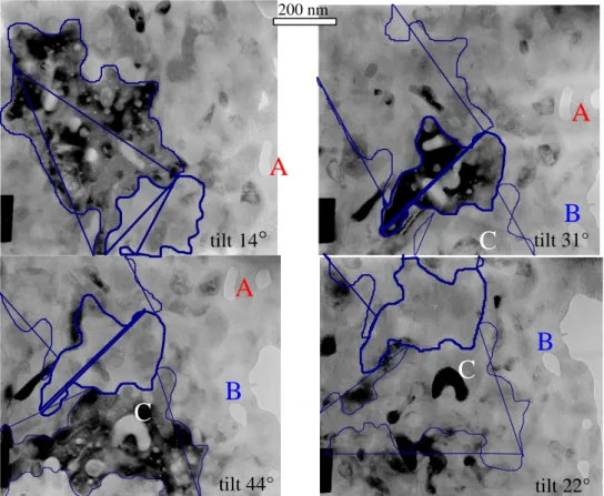
200 nm
A
B
C
A
B
C
A
B
C
tilt 14°
tilt 31° tilt 44° tilt 22°Fig.5: Microstructure after a heat Fig.6: Grain growth after a treatment treatment of 4 hours at 1400°C of 4 hours at 1400°C.
After 5 hours at 1200°C the microstructure had the same appearance as that of the as received fibre: the sizes and shapes of the aggregates had not changed. The microstructure begun to grow from 1300°C. After 4 hours at 1400°C, the shape of the mullite aggregates had changed and they appeared to be more faceted as seen on Fig.6. The size of alumina grains had increased and their interfaces were much more angular than those of the as-received fibre (Fig.5 and 6). The average length of these grains was 200 to 300 nm.
A-3. Mechanical properties
Considerable variation in fibre diameter was observed so that the diameter of each fibre was measured prior to tensile testing. Ceramic fibres show considerable scatter in their mechanical properties: failure strength depends on the gauge length and is controlled by the presence of defects and their distributions. In order to determine the room temperature properties 30 tests were conducted at each gauge length.
y = -9.95E-02x + 8.48E-01 0.2 0.3 0.4 0.5 0.6 0.7 1 2 3 4 5 6 ln gauge length
ln median tensile strength
Fig.7: Median tensile strength as a function of the gauge length.
Gauge length (mm) 250 100 50 25 10 5
failure strain (%) 0.52 0.62 0.67 0.66 0.81 0.95
Young modulus (GPa) 249 250 255 256 256 243
Median tensile strength (GPa) 1.29 1.52 1.60 1.74 1.9 1.9
Table 1. Room temperature properties for different gauge lengths. 200 nm
Failure strains were small and never exceeded 1%. However they were superior to those of the FP pure α-alumina fibre. There was no influence on the stress rate on the mechanical properties at room temperature.
A-4. Fracture analysis at room temperature
The fibres showed linear elastic behaviour with brittle failure. The fracture surfaces of all fibres broken at room temperature had the same appearance and were planar. Crack propagation was intragranular. Fig.1 shows a failure surface of an as-received N720 broken at room temperature with a failure strength of 1.30 GPa.
B. High temperature characterisation B-1. Tensile tests
Up to 1000°C the fibres showed perfectly linear elastic behaviour. At higher temperatures (1100°C to 1200°C) fibres broke very quickly at loads less than 2g. No plasticity was observed during high temperature tensile testing and the fibres still exhibited brittle failure surfaces. 0 0.5 1 1.5 2 0 400 800 1200 Temperature (°C)
Tensile strength (GPa)
10 100 1000 10000
0.1 1 10 100 1000 10000
Stress rate (MPa/s)
Tensile strength (MPa)
1100°C, as received 1100°C, after 1200°C, 3h 1200°C, as received
Fig.8: Tensile strength at a constant strain Fig.9: Failure strengths at 1100°C and rate of 6.10-5/s as a function of temperature 1200°C of as-received and heat treated
fibres as a function of stress rate. For each temperature 35 fibres were tested. Around 1000°C the strength suddenly dropped as shown in Fig.8. At 1200°C the failure strength was 0.24 GPa at a strain rate of 6.10-5/s which is only 14% of the room temperature failure strength. The dependance of the fracture strengths on the strain rates as shown in Fig.9 indicating subcritical crack growth.
B-2. Fracture analysis
Fig.10: Fracture surface at 1200°C Fig.11: microstructure after a heat treatment in the presence of lanthanum chromite.
Up to 1000°C, the fibre fracture surfaces had the same appearance as those at room temperature however from 1100°C the fracture surfaces were drastically modified. Failure was seen to be always initiated at a large defect (up to 1.5µm) consisting of α-alumina platelets. As can be seen in Fig.10 the fracture surfaces present an area which fans out symmetrically from these platelets and consists of two zones. The fracture surface is at first rough due to intergranular failure and then smoother due to intragranular failure.
C. Influence of a heat treatment on the mechanical properties
Temperature of heat treatment 1100°C 1200°C 1300°C 1400°C
Young modulus (GPa) 282 284 291 290
STD 16 % 18 % 17 % 9 %
Table 2: E modulus at room temperature after heat treatment of 5 hours.
The room temperature tensile strength dropped by approximatively 10 % after a four hour heat treatment at 1200°C at a strain rate of 6.10-5/s. An increase in Young's modulus with heat treatment can be seen to have occured. SEM observations show that fracture surfaces have the same appearence than that of as received fibres.
D. Influence of impurities combined with a heat treatment
The sudden fall in strength around 1100°C coupled with the presence of large grain growth at the fracture surfaces, which was not seen after heat treatment, suggested that the fibres were being weakened by the combined effects of the applied load as well as external effects possibly amplified by impurities in the fibres. Lanthamum chromite was first investigated as it was the composition of the furnace heating element. Fibres, heat treated without load in contact with lanthanum chromite, showed a drop of 35% of their room temperature properties. Furthermore, Fig.11 shows the growth of small α-alumina platelets on a fibre heat treated at 1200°C for 24 hours in the vicinity of a lanthanum chromite tube. EDX SEM analysis of the fibre surface showed no impurities of a concentration > 0.2 %. However these platelets were smaller than the one observed on high temperature tensile fracture surfaces.
E. Creep properties -0.35% -0.15% 0.05% 0.25% 0 20000 40000 60000 time (s) Strain 1100°C, 300 MPa 1050°C, 300 MPa 900°C, 300 MPa 1100°C, 230 MPa ε = 7.10−8/S ε = 2.10-8 / s 0% 1% 2% 3% 4% 0 400000 800000 time (s) Strain 120 MPa 150 MPa 100 MPa ε = 3.5.10-9 / s ε = 3.3.10-8 / s
Fig.12: Creep curves of monofilaments Fig.13: Creep curves of bundles of fibres. Many creep tests were conducted on monofilaments at different stresses and temperatures. It was very difficult to observe steady state creep as the fibres rapidly broke because of
subcritical crack growth. At high temperature or stress (above 0.2 GPa at 1100°C) catastrophic failure during primary creep occurred in less than 3 hours. Only one fibre was found to creep and survive after 12 hours. For this test at 1100°C and 0.23 GPa a steady state creep rate of 7.10-8/s was measured (Fig.12). Shrinkage was observed from 800°C to 1000°C in Fig.12. As monofilaments broke because of SCG some creep tests were performed on bundles of 400 fibres. The applied stress indicated in Fig.13 are the minimum stresses applied as it is assumed that all the fibres in the bundle support the load. This is unlikely to have been the case. In these tests the fibres were found to survive for several days at 1200°C whereas a monofilament never survived more than five minutes at 1200°C whatever stress was imposed.
IV. DISCUSSION
A. Microstructure
As schematised on Fig.14 the Nextel 720 fibre is composed of aggregates of mullite composed of grains separating by low angle disorientations and enclosing round or elongated
α-alumina grains. The elongated alumina grains have got aspect ratios of up to 6 and they are mainly orientated in the fibre axis direction.
B. Cell parameters of the mullite
Mullite is the only stable crystalline compound in the Al2O3-SiO2 system under normal
atmospheric pressure. It is commonly described as having a composition ranging from 3Al2O3:2SiO2 (60 mol % Al2O3) to 2Al2O3:SiO2 (66 mol % Al2O3) and crystallising in the
orthorhombic system. However it has been shown [4,5] that solid solution mullite can occur over a larger range of compositions from 58 to more than 75 mol % alumina when crystallised from a melt. Furthermore, Ossaka and Schneider [6,7] showed the occurrence of a new mullite-like phase. In the diffraction diagram of this new phase the pairs of 120/210, 420/240, 041/401, 250/520 reflections of ordinary mullite were found to merge into each other forming a single peak. The lack of splitting of these reflections means that the length of the a and b constants became equal and that the symmetry was tetragonal instead of orthorhombic. This phase was described as pseudo-tetragonal [6] because its tetragonal character is thought to be due to twinning and/or domain formation of orthorhombic structural units in an elementary cell scale. This mullite is usually formed from highly reactive metal organic compounds. The phase is metastable and transforms gradually to orthorhombic mullite at temperatures above 1000°C. The lack of the 401, 120, 250 peaks of the Nextel 720 mullite in the as received conditions indicates that this phase is the pseudo-tetragonal phase described by Ossaka and Schneider. The cell parameters of the as-received fibre were calculated from the positions of the mullite peaks 331, 421 and 002. a = 7.60 Å, b = 7.65 Å and c = 2.89 Å and they were very close to that found by Ossaka. The lattice parameters of the fibre heat treated for 5 hours at 1200°C were calculated from the same peaks than for the as received fibre. a = 7.58 Å, b = 7.67 Å, c = 2.88 Å. After a heat treatment of 24 hours at 1400°C the values are a = 7.54 Å,
α-alumina grains Fig.14: Schematisation of the microstructure.
b = 7.68Å, c= 2.88 Å. After the heat treatment at 1400°C the splitting of the peaks 210/120
520/250, 420/240, 410/140 indicated clearly a change of the mullite structure which became orthorhombic.
C. Nextel 720 composition
Cameron [8] and later Ban [9] expressed numerically the linear increase of the alumina content in mol % of the mullite with the augmentation of the lattice parameter a. From Ban's expression and from the value of the parameter a calculated before, the mullite of the Nextel 720 fibre was calculated to contain 68 mol % alumina. As the fibre is composed of 15% weight silica and 85% alumina, we can calculate its composition which is 69% alumina. From the densities of alumina and mullite, the volume composition of the Nextel 720 fibre was calculated to be 74 % mullite and 26 % α-alumina. Finally the as received Nextel 720 fibre is composed of aggregates of a metastable pseudo-tetragonal mullite phase enclosing α-alumina grains. The volume of the mullite phase is 3 times that of the alumina.
The alumina content in the heat treated orthorhombic mullite was calculated to be 59.6 mol % using the same relationship. The mullite lost alumina while recristallising in the orthorhombic system and that is the explanation for the increase of the α-alumina peaks. The volume composition of the fibre after a heat treatment of 24 hours at 1400°C was 52.6 % mullite and 47.4 % α-alumina. The lost of alumina occured gradually during heat treatment as indicated by the value of a calculated after the heat treatment at 1200°C.
D. Rule of mixtures for physical properties of a two-phase material
Young modulus of a two phase material is not dependant exclusively on the amounts of its constituents so there is no exact expression for the elastic modulus as a function of constituent fraction and morphology. However, Paul [10] has proposed a semi-empirical expression that gives a good approximation of the modulus for uniforme distributed microstructures.
220 270 320 370 420 0 0.2 0.4 0.6 0.8 1 mullite % (volume)
Young modulus (GPa)
Fig.15: Expression of E as a function of the mullite content.
Fig.15 shows the Paul expression of E plotted for the mullite-alumina system. The Young's modulus given by the Paul relation for the as received Nextel 720 fibre, would be 270 GPa without any porosity. The actual value is around 251 GPa. From these values and the Mackenzie [11] relationship we can calculate the porosity of the as received fibre which gives a value around 4%. After a heat treatment at 1400°C, the proportion of the two phases was found to have changed and the E modulus given by Paul's relationship was 304 GPa. The
measured value was 288 GPa (see Table 2) suggesting a porosity after heat treatment of less than 3%. That explains the shrinkage observed during creep tests.
E. Subcritical crack growth and occurrence of alumina platelets
Failure of ceramics at elevated temperatures usually occurs by either slow crack growth (SCG) or creep rupture depending on the stress level and temperature conditions. Failure due to SCG takes place at high stresses within a relatively short time, and generally involves the extension of a single dominant processing flaw to the critical size. Wiederhorn and Hockey [12] observed the nucleation and growth of cracks in vitreous bonded aluminium oxide at elevated temperatures for strains of 0.08% to 0.12% and suggested that the crack distribution was a consequence of heterogeneous deformation within the material. Once nucleated crack propagation occured along grain boundaries as long as the stress for crack propagation was maintained until failure occured. Dey and al [13] assumed that in ceramic polycristals with viscous grain boundary, since both creep deformation and SCG may be governed by the same mechanism, eg. cavitation in the grain boundary phase, they are interrelated so that failure strain may simultaneously be controlled by the creep strain rate and the SCG rate. It was shown in Fig. 9 that failure strengths of the Nextel 720 fibres were dependent on the stress rate. This suggests that failure occurs by SCG. Furthermore alumina platelets (Fig.10) were present in each tensile test as soon as the temperature reached 1200°C independently of the stressing rate and even for tests lasting for only one second in the furnace with a heating element of lanthanum chromite. These platelets did not appear after a heat treatment of 24 hours at 1400°C without any stress in an alumina tube. However Fig.11 shows the growth of small platelets after a 1200°C heat treatment with no applied stress in a lanthanum chromite tube. It seems that platelets formation requires external contaminants and is greatly enhanced by stress. This hypothesis was confirmed by the creep tests performed on bundles of fibres. These bundles were found to survive as, presumably, the inner fibres were protected from the external contaminants by the outer fibres. As the growth of platelets is an extremely rapid and local phenomena the driving mechanism must be diffusion through a liquid phase due to the presence of local heterogeneities in the fibre microstructure. This has been studied by Change and Page [12] who have shown that creep crack growth in ceramics can occur by a direct mass transport process dictated by surface and grain boundary diffusion through a liquid phase. This may be the phenomena involved in the growth of the platelets in the Nextel 720 fibre. Indeed the presence of few ppm of cations can drasticaly reduce the cristallisation temperature of silica so that external contamination could be responsible for the formation of a silica liquid phase at grain boundaries.
F. Creep behaviour
The most common creep mechanism of polycrystalline oxide fibres is grain boundary sliding accommodated by diffusional flaw and interfaces dislocation mobility. The particular microstructure of the Nextel 720 fibre reduces the grain boundary surface because of the aggregates which act as single big entities. Therefore the density of interfaces and so the grain boundary diffusion paths are reduced. Furthermore the complex cell structure of mullite as well as the wavy boundaries of the aggregates are two important parameters in the reduction of the strain rate of this fibre. As a consequence the creep resistance of Nextel 720 is better than that of other polycrystalline oxide fibres. Indeed the creep rate at 1100°C under 0.23 GPa is seven times smaller than that of FP fibres (pure alumina) with the same conditions (5.10-6/s) [1]. However SCG occurs from 1000°C during creep tests on monofilaments and causes premature failure of the fibre before reaching the secondary creep stage. Much longer test
were possible with fibre bundles than with single fibres and led to lower rates suggesting that single fibres were not completely in secondary creep.
CONCLUSION
The two phase microstructure of the as-received Nextel 720 fibre was found to be composed of pseudo tetragonal mullite aggregates enclosing elongated or round shaped α-alumina grains. After annealing the fibre at 1400°C the mullite structure became orthorhombic while losing alumina. A small increase of the Young's modulus was observed because of the change of relative amounts of alumina and mullite and a diminution of the porosity.
Thanks to its original microstructure the fibre was found to have a reduced creep rate when compared to other polycristalline oxide fibres but was found to be extremely sensitive to external contaminants and to suffer from premature failure due to SCG. Even though the Nextel 720 fibre has a good creep resistance creep the effects of different environements on its SCG behaviour should be more accurately investigated because it will be the most limitating parameter for its use in high temperature composites.
REFERENCES
[1] V.Lavaste, M.H. Berger and A. R. Bunsell, “microstructure and mechanical characterics of alpha-alumina-based fibres”, Journal of Materials Science, Vol. 30, 1995, p. 4215-4225.
[2] D.M.Wilson, S.L. Lieder and D.C. Luenburg, “microstructure and high temperature properties of nextel 720 fibers”, Ceramic engineering and Science Proceedings, Vol. 16, N° 5, 1995, p. 1005-1014.
[3] A.R. Bunsell, J.W.S. Hearle, “an apparatus for fatigue-testing of fibres”, J. Phys. E Sci.
Instrum. 4 (1971) 868.
[4] W. E. Cameron, “Mullite:a substituted alumina”, American Mineralogist, Vol. 62, (1977), pp 747-755.
[5], W.M. Kriven, J.A. Pask, “Solid Solution Range and Microstructures of Melt-Grown Mullite”, J. Am. Ceram. Soc, Vol 66 N° 9, (1983), pp. 649-954.
[6] J. Ossaka, “Tetragonal millite like phase from Co-precipitated Gels”, Nature, Vol 191 (1961), pp. 1000-1001.
[7] H. Schneider, T. Rymon-Lipinski, “Occurrence of Pseudotetragonal Mullite”, J. Am.
Ceram. Soc., 71 [3] C162-C164 (1988).
[8] W.E. Cameron “Composition and Cell Dimensions of Mullite”, Ceramic Bulletin, Vol. 56,No 11 (1977).
[9] T. Ban and K. Okada, “Structure Refinement of Mullite...”, J. Am. Ceram. Soc., Vol 75, N° 1 (1992), pp. 227-230.
[10] B. Paul, “Prediction of elastic constants of multiphase materials”, Trans. Met. Soc. AIME, New York (1976).
[11] J. K. Mackenzie, Proc. Phys. Soc. London, 63B (1950) pp.2-11.
[12] S.M. Wiederhorn and B.J. Hockey “Nucleation and Growth of Cracks in Vitreous-Bonded Aluminium Oxide at Elevated Temperatures”, J. Am. Ceram. Soc., Vol 69, N° 10 (1986), pp. 725-731.
[13] N. Dey, D.F. Socie and K.J. Hsia, “Tensile Creep Behaviour of a Vitreous-Bonded Aluminium Oxide under Static and Cyclic Loading”, J. Am. Ceram. Soc., Vol 79, N° 9 (1996), pp. 2353-2363.
[14] K.S. Chan and R. A. Page, “Creep Damage Development in Structural Ceramics”, J.