HAL Id: hal-01448784
https://hal.univ-brest.fr/hal-01448784
Submitted on 29 Jan 2017
HAL is a multi-disciplinary open access
archive for the deposit and dissemination of
sci-entific research documents, whether they are
pub-lished or not. The documents may come from
teaching and research institutions in France or
abroad, or from public or private research centers.
L’archive ouverte pluridisciplinaire HAL, est
destinée au dépôt et à la diffusion de documents
scientifiques de niveau recherche, publiés ou non,
émanant des établissements d’enseignement et de
recherche français ou étrangers, des laboratoires
publics ou privés.
Dynamic Round-Trip Engineering in the context of
FOMDD
Glenn Cavarlé, Alain Plantec, Steven Costiou, Vincent Ribaud
To cite this version:
Glenn Cavarlé, Alain Plantec, Steven Costiou, Vincent Ribaud. Dynamic Round-Trip Engineering in
the context of FOMDD. 11th International Workshop on Smalltalk Technologies, Aug 2016, Prague,
Czech Republic. pp.1 - 7, �10.1145/2991041.2991056�. �hal-01448784�
Dynamic Round-Trip Engineering in the context of FOMDD
Glenn Cavarlé
Alain Plantec
Steven Costiou
Vincent Ribaud
Univ. Bretagne-Occidentale, UMR CNRS 6285, Lab-STICC, F-29200 Brest, France{glenn.cavarle, alain.plantec, steven.costiou, vincent.ribaud}@univ-brest.fr
Abstract
In the context of Feature-Oriented Model-Driven Develop-ment, round-trip engineering remains challenging because of the one-to-many relationship that exists between a source model and its implementation parts. In this paper, we present CrossFabrik, an approach that allows round-trip engineer-ing with dynamic assessment of generated implementations. Such an approach relies on the reflective capability of the de-velopment environment. An implementation of our approach within Pharo is also presented.
Keywords feature-oriented development, round-trip engi-neering, model driven engiengi-neering, smalltalk
1.
Introduction
Model-Driven Development (MDD) promotes models as first-class entities in software design. Feature-Oriented De-velopment (FOD) is a paradigm used in Software Prod-uct Line (SPL) that operates through features composi-tion to produce software variants. Such a paradigm im-poses a one-to-many relationship between a model and the executable artefacts which are produced from it. Feature-Oriented Model-Driven Development (FOMDD) [1, 2] is a blend of FOD and MDD that exploits features composition to create models and that use model transformations to pro-duce software variants.
Basically, MDD, FOD and FOMDD share the same protocol to assess a software during development. The source arte-facts cannot be directly executed. Instead, transformations have to be performed to produce an executable artefact from the source artefacts. Hence, from the editing of source arte-facts to the execution of the generated ones, a typical devel-opment cycle can be described as follows. First, the source code has to be generated from the source artefacts, then the source code has to be compiled and the resulting executable artefact has to be deployed before it can be actually run. In case of an issue occurring during the execution, the faulty running context has to be observed to discover the defec-tive source artefact. We characterize this step as the feedback process. After the developer has fixed the source artefact, the assessment protocol has to be achieved again.
The consequence of such a process is a break between the editing of the source artefact and the execution of the
gener-ated artefact. After the developer has fixed the source arte-fact, it may be tedious to come back to the original execution context and to continue a validation process. Moreover, the developer faces a traceability issue between a malfunction that is observed during execution and the source artefact that should be fixed [3].
Round-Trip Engineering can be used to allow the editing of generated artefacts while keeping source artefacts synchro-nized. The goal of round-trip engineering is keeping a num-ber of artefacts, such as models and code, consistent by prop-agating changes among the artefacts. Round-trip engineer-ing is a special case of synchronization that can propagate changes in multiple directions, such as from models to code and vice versa. Round-trip engineering is hard to achieve in a general setting due to the complexity of the non-isomorphic mappings between the artefacts [4], especially in the context of FOMDD.
This paper presents a dynamic Round-Trip Engineering in the context of FOMDD. This solution is part of CrossFabrik, our engineering environment for cross-platform software de-sign. The goal is to reduce the development cost by maxi-mizing the use of the development environment before the platform specific artefacts are generated. With CrossFabrik the model editing as well as the simulation of the software variants are performed closely within the development envi-ronment.
The three contributions of this paper are:
•We present the CrossFabrik language, our specific lan-guage dedicated to model specification in the context of FOMDD.
•We describe our dynamic Round-Trip Engineering which preserves the one-to-many relationship between a source model and the executable artefacts.
The remainder of this paper is organized as follows: the next section recalls the main concepts regarding feature mod-elling. Section 3 introduces the CrossFabrik language that is used to specify source models. Section 4 presents a moti-vating example that illustrates a typical situation that arises in FOMDD and that highlights specific issues in software as-sessment. In Section 5, we describe our approach regarding software assessment in the context of FOMDD. A focus on the Pharo reflective model is given in Section 6. Section 7
explains how the dynamic Round-Trip Engineering is im-plemented using the Pharo reflective capabilities. Then, we present in Section 8 the dedicated tools to edit models and how we reuse the Pharo infrastructure to manipulate and de-bug executable artefacts. Finally, in Section 9, related work is presented before concluding in Section 10.
2.
Background: Feature Modelling Overview
The concept of feature modelling comes from Software Product Line [5].A feature has been defined as "a logical unit of behaviour specified by a set of functional and non-functional require-ments"[8] and usually referred as a user-visible aspect of a software.
A Feature Model [6, 7] is a logical representation of a ware family. A software family consists in a set of soft-ware which share mandatory and optional features. A Fea-ture Model is specified as a tree of named nodes.
From a Feature Model, multiple software variants can be de-fined. A software variant is itself defined by a configuration. A configuration is a feature selection among the nodes of the Feature Model.
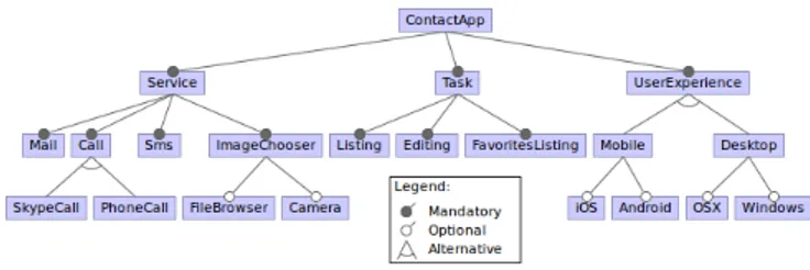
Figure 1. An example of a Feature Model.
Figure 1 shows the Feature Model of the ContactApp soft-ware family. Each node specifies a feature. In this example, a particular configuration could be made of the following fea-tures: Mail, PhoneCall, Camera, Task and Android. Another configuration could be define to use the iOS feature instead of the Android one.
Implementing features is under the responsibility of the de-velopment environment. Each environment provides its own approach to implement software artefacts according to spec-ified features.
The following section presents the meta-model that is used in CrossFabrik to specify the software artefacts.
3.
Implementing Features With CrossFabrik
The CrossFabrik language consists in a meta-model that in-tegrates the concept of feature. It allows the implementation of a Feature Model. The goal is to specify the mapping be-tween features and supporting software artefacts.The main elements of the meta-model are depicted in Fig-ure 2. Regarding the structural aspects, the CrossFabrik lan-guage is EMOF-inspired [9]. The FabrikElement is the root abstraction for elements such as a class, an attribute and a method description. These elements are represented in CrossFabrik by, respectively FabrikClass, FabrikAttribute and FabrikMethod.
Figure 2. CrossFabrik meta-model fundamentals
The FabrikAttribute element describes an instance variable. Such an element can be associated with data validators and with data filters to specify the way an attribute value can be accessed.
The business behaviour is described through the Fabrik-Methodelement. A FabrikAstWrapper is associated with a FabrikMethod element through its body property to repre-sent the source code.
A FabrikFeature entity is a reference to a feature which is expressed in a Feature Model. Any element can be associ-ated with multiple features and any feature can be associassoci-ated with multiple elements.
A particular configuration namely an instance of FabrikCon-figurationis made of a set of FabrikFeature instances. Thus, the production of a software variant consists in three main steps. First, features are specified by a Feature Model. The configurations are defined by selecting relevant features. Then, features can be implemented using elements of the CrossFabrik meta-model. Finally, each software variant can be generated from a CrossFabrik model associated with a particular configuration.
4.
A Motivating Example
This section presents an example based on a User entity. For all software variants of the software family, a User is made of an email attribute. But, in our example, the developer needs to implement two different variants. The first with a Locationfeature and the second without it.
Figure 3 depicts a Feature Model for this example. The root feature is named Root. Location is an optional feature which adds the possibility for a user to be geolocalized. In this case, two additional properties are required for the management
of a User, namely the location field and the updateLocation method.
Figure 3. The User model and the associated features. Given that from Root, there are two possible configurations, as a consequence, there are two possible implementations for one User model. It is depicted by the implementation-of relationship in Figure 4.
Figure 4. The User model and its two implementations. These two implementations are automatically generated from the source model together with the specification of the configuration (e.g the actual selection of features).
In currently available Feature-Oriented development en-vironments, after code generation, the generated classes User_Impl1 and User_Impl2 are self-contained and are no longer linked with the related User model.
Typically, this situation implies the following difficulties:
•During the assessment of a particular implementation, each time an issue occurs, the current execution has to be stopped. Then, the User model has to be fixed according to the relevant feature and finally the source code have to be regenerated. This clearly breaks the development flow.
•While debugging the Location feature, a developer may need to dynamically manipulate the User model. But be-cause of the code generation process, this may be impos-sible.
•A developer may choose to investigate a particular solu-tion at implementasolu-tion side. As an example, the devel-oper may want to tune the Location feature implemen-tation. But in this case, after the investigation is over,
the User model has to be manually synchronized with the new implementation. Moreover, changing the imple-mentation of the base User model (without the Location feature) imposes the validation of all the dependent con-figurations. If the developer decides to directly change its implementation, then he has to manually maintain the User model and to regenerate the other configurations.
The CrossFabrik approach supports dynamic Model-Driven RTE. It consists in using the same environment at design time as well as at running time. The CrossFabrik approach is presented in the next section.
5.
The CrossFabrik RTE Approach
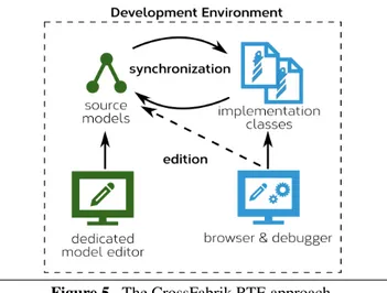
With CrossFabrik, the modelling and the execution take place within a unique environment at design time as well as at running time. As depicted by Figure 5, the dynamic RTE consists in an incremental and continuous synchronisation between a source model and intermediate implementation classes used for simulation purpose.
A source model is specified using the CrossFabrik language and implementation classes are generated automatically for each configuration.
In CrossFabrik, information duplication is avoided to allow the dynamic synchronization. A generated implementation class is associated with the model element that describes it. At runtime, this association allows the dynamic synchroniza-tion of the source model from any instance of the generated class. As an example, a generated class method does not con-tain any source code. The method source code is only de-scribed in the source model and it is dynamically used dur-ing the assessment of the generated class.
Figure 5. The CrossFabrik RTE approach.
The development cycle can be decomposed in two phases. First, the developer starts to model a software family by using dedicated editors. Depending on the current synchro-nization strategy in use, the implementation classes can be
either generated on demand or automatically during the edit-ing. Then, the developer can instantiate the generated imple-mentation classes to assess a software variant.
The CrossFabrik approach deeply relies on reflective capa-bilities of the development environment especially for the dynamic RTE and for the debugging. For the validation of our approach we use the Pharo Environment.
6.
A Focus On The Pharo Reflectivity
In Pharo [10], a class, an instance variable, a class variable and a method namely Class, Slot, ClassVariable and Com-piledMethod, are first-class objects. Using the reflective ca-pabilities of Pharo, it is possible to dynamically change the structural aspects of a Class. Such a change affects imme-diately the running system (e.g. all instances of the updated class).
In the scope of a class, Slot and ClassVariable instances [11] define the reading and the writing behaviour of instance variables and of class variables. Slot and ClassVariable can be subclassed to provide a specific behaviour.
Any object can play the role of a CompiledMethod as long as it is able to responds to the specific message run:with:in:. An object that responds to run:with:in: is called a method wrapper or a method proxy [12].
To maintain the dynamic synchronization between Cross-Fabrik elements and generated implementation classes, the CrossFabrik implementation of RTE relies on slots and method proxies. This RTE implementation is presented in the next section.
7.
The RTE Implementation
A model may have several implementation variants accord-ing to the features set. Then, for one model, the round-trip implementation has to keep multiple implementation classes synchronized. Any RTE implementation automatically man-ages forward and reverse engineering:
•First, the forward engineering capability. Any change in a model have to be automatically applied to related Pharo classes.
•Second, the reverse engineering capability. Any change in a Pharo class have to be automatically reflected in the source model.
Because of the one-to-many relationship, implementing the reverse engineering can be tedious. A change in a Pharo class can also impact implementation classes generated from other configurations. Moreover, reverse changes have to be controlled and validated before being applied to models. Any ambiguity must be resolved and improper changes must be rejected in order to preserve the model integrity.
The forward and the reverse engineering are implemented by a mediator class named ChangeManager. The implemented mechanisms are depicted in Figure 6:
•Forward engineering involves generating Pharo classes from a source model. This mechanism is event-based. Events are emitted each time a source model is updated. Then, the ChangeManager reacts by propagating changes in the related Pharo classes. The ChangeManager takes care of the one-to-many relationship between the source model and the implementation classes.
•Reverse Engineering is change-based. It relies on the re-definition of the default update behaviour of the gener-ated classes at class definition level as well as at method definition level. In case of a structural change of a class or in case of a method definition change, the default behaviour is prevented, instead, the ChangeManager is asked to update the related source model.
Figure 6. The ChangeManager acts as a mediator object.
7.1 The Forward Engineering
The forward engineering takes place each time a source model is updated. When an CorssFabrik element is changed, an event is emitted by the element. The ChangeManager reacts to these events by updating the generated classes. In order to implement the RTE, CrossFabrik has to manage the way a class is installed in the system and has to change the default behaviour. For that purpose, CrossFabrik imple-ments its own meta-entities to be used in place of Slot, Class-Variable and CompiledMethod to redefine the reading and the writing the behaviour of slots and the way a method is executed.
The use of these CrossFabrik meta-entities for our User ex-ample is depicted by Figure 7. Instead of using a Slot, the mail attribute is implemented through an instance of Fab-rikAttributeSlot. Instead of using a CompiledMethod, the up-dateLocation method is implemented though an instance of FabrikMethodProxy. Instead of using a ClassVariable, the User source model is referenced by a FabrikClassVariable instance. FabrikAttributeSlot, FabrikClassVariable and Fab-rikMethodProxy hold a reference to the CrossFabrik ele-ments.
Figure 7. User model instance (left) with related meta-entities (right).
The running of a software variant relies on a proxy mech-anism from the generated class to the source model. Fig-ure 8 depicts the implementation of the run:with:in: method of the FabrikMethodProxy. It shows that the execution relies only on the source code specified in the source model. First, the method proxy retrieves the AST method node from its model. Then, the AST method node is converted to a Com-piledMethod before being executed.
FabrikMethodProxy>>run: aSelector with: args in: aReceiver ^ (selfmodel astMethodNodeUsing:selfmethodClass)
compiledMethod
valueWithReceiver: aReceiver arguments: args
Figure 8. Implementation of the run:with:in: method of the FabrikMethodProxy.
7.2 The Reverse Engineering
To perform the reverse engineering, the ChangeManager has to be aware of changes applied in implementation classes. In Pharo, object update is the responsibility of the objects themselves. Thus, we can implement a new update strategy directly in implementation classes.
Two kind of changes have to be intercepted and propagated at model side:
•The structural changes: the addition/deletion of instance variables or of methods of an object.
•The behavioural changes: the modification of a method’s body.
In Pharo, all structural changes are delegated to the Pharo-ClassInstaller. In CrossFabrik, the PharoClassInstaller is not directly used by generated classes. Instead, the ChangeMan-ager act as a mediator between the generated classes and the PharoClassInstaller.
When an instance variable is added, the ChangeManager is asked to update the related source model. It first check the validity of the change, then it applies the change on the related source model and finally the forward engineering takes place.
In Pharo, the methods management is under the responsi-bility of the class itself. When a method is compiled, the
class method named addAndClassifySelector:withMethod: is invoked to perform the actual changes. In CrossFabrik, this method is redefined to delegate method changes to the ChangeManager. Figure 9 depicts how the class method ad-dAndClassifySelector:withMethod:is redefined. In case of the update of an existing method, the ast of the source model is directly updated. In case of a new method or of a method removing, the request is forwarded to the ChangeManager in order to perform relevant changes on source model.
Userclass>>addAndClassifySelector: s withMethod: newCm [...]
selfmethodDict at: s ifPresent: [ :oldProxy |
oldProxy class isCompiledMethod ifFalse: [ ^ oldProxy model updateFromImpl: newCm ] ]. ifAbsent:[
ChangeManagercurrent
createMethodFromImpl: newCm inModel: _model]. [...]
Figure 9. The redefinition of the addAndClassifySelec-tor:withMethod:method.
8.
Tools Support
The Pharo infrastructure is fully usable with CrossFabrik. However, to ease the edition of source models and the debug-ging of generated classes, a set a tools has been specifically implemented. These tools are presented in this section.
8.1 Editing Models
Dedicated tools including editors and a specific declarative language were implemented to manipulate models. Cross-Fabrik provides an Integrated Development Environment (IDE) for that purpose.
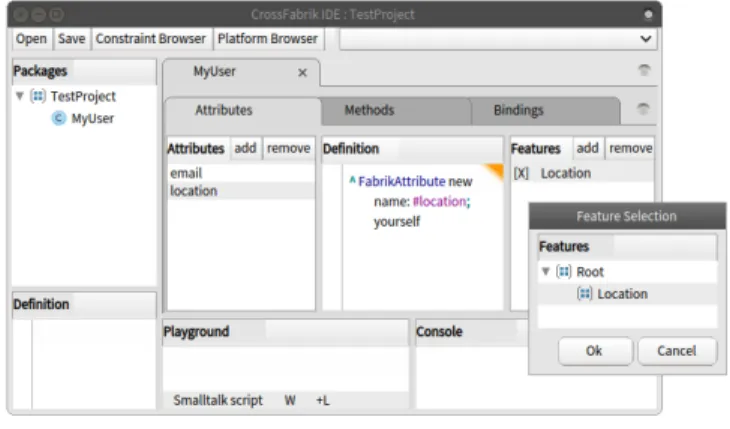
Figure 10. The CrossFabrik IDE.
Figure 10 shows the CrossFabrik IDE for models editing. It is mainly composed at left by a package browser from which models can be opened. Tabulations are presented at the center. They show the content of the models. Attributes and methods can be edited and can be associated with fea-tures. The popup window at bottom right shows a view of the Feature Model currently in use.
From this package browser, the developer can also open a model in a textual mode. Instead of the default model editor, a text editor is opened that contains the textual representation of the selected model.
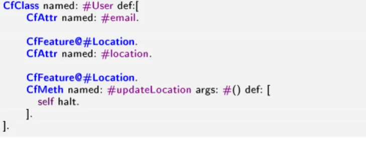
As an example, the Figure 11 shows the declarative syntax used to describe the User model.
CfClassnamed:#Userdef:[
CfAttrnamed:#email.
CfFeature@#Location.
CfAttrnamed:#location.
CfFeature@#Location.
CfMethnamed:#updateLocationargs:#() def: [
selfhalt. ]. ].
Figure 11. The declarative syntax use to describe the User model.
This declarative syntax can be directly executed within any Pharo editor.
8.2 Extending The Pharo Debugger
Pharo provides the GTDebugger [13] that offers a way for developers to adapt visualization to new domains and sce-narios. It is object-centric and retrieves the relevant visual-izations directly from the inspected object. Thus, the debug-ger is dynamically adapted when a particular inspected ob-ject contains methods that describe new visualization to use. As an example, Figure 12 shows the debugging of one User implementation.
Figure 12. The debugging of one User implementation. The CrossFabrik debugging visualization is composed of two columns. The first column lists the attributes and the methods of the current inspected object. When an item is selected in the list, its source model is displayed below the list using the CrossFabrik textual representation. This representation can be edited within the browser. The second column displays the structure of the source model. As any
other inspected object, the source model can be manipulated and edited.
9.
Related Work
In this Section we discuss related work on round-trip engi-neering. As far as we know, CrossFabrik is the only environ-ment that provide dynamic debugging and RTE support in the context of FOMDD.
In [19], a Change-Oriented Advanced Round-Trip Engineer-ing (COARTE) is envisioned. In COARTE, changes are con-sidered as first-class objects and the entire set of changes objects represents the complete history of a software sys-tem. As in COARTE, CrossFabrik uses a change-oriented RTE. Our implementation relies on an event model and on the change mechanism provided by Pharo. But we do not maintains the history of changes made. Changes cannot be stored and replayed.
COARTE also provides multiple views on a software system with the distinction between static and runtime views and be-tween design and implementation views. In CrossFabrik this distinction is also made. The CrossFabrik IDE depicts how a software is designed whereas the Pharo code browser and the debugger depict respectively how a software is statically implemented and how implementation instances live in the system.
But COARTE does not address the issue of the synchroniza-tion of multiple implementasynchroniza-tions from the same model. In CrossFabrik, the first requirement regarding the RTE is to maintain this one-to-many relationship. As far as we know, COARTE does not allow such a kind of synchronization. SelfSync [18] is an approach and tools for providing dy-namic support for RTE in the context of Entity-Relationship diagrams. SelfSync is implemented in Self, a prototype-based dynamic object-oriented programming language, en-vironment, and virtual machine. In SelfSync, the modelling and the execution take place within a unique environment. A source model and the corresponding implementation ob-ject are one and the same. Both share the same structure and the same behaviour namely its prototype and its traits, respectively. In CrossFabrik the modelling and the execu-tion also take place within a unique environment at design as well as at running time. As SelfSync, CrossFabrik con-sists in a dynamic support for RTE, synchronizing a model and its implementation parts even at runtime. In CrossFab-rik, the behaviour is also shared between source models and implementation classes. It is made of AST nodes that can be produced at design time and executed during the assessment of implementation classes.
Our solution differ from SelfSync in the management of the relationship between model and implementation parts. In CrossFabrik, because a source model may have several im-plementations, the same object cannot be used,
implementa-tion classes have to be generated and a one-to-many relaimplementa-tion- relation-ship have to be maintained. Such a synchronization cannot be achieved with SelfSync. Moreover, SelfSync do not sup-port a runtime RTE in the reverse direction [21]. In Cross-Fabrik, we provide such a reverse support especially during the debugging process. From an instance of an implementa-tion class, the source model can be inspected and updated. Such updates affect automatically the source model, its im-plementation classes and their instances currently in use.
10.
Conclusion And Future Works
This paper addresses the issue of software assessment dur-ing development in the context of Feature-Oriented Model-Driven Development. Typically, assessing a software in the context of FOMDD involves generating the final software from models and executing it separately from models. In this paper, we presented CrossFabrik, an environment that allows debugging as well as round-trip engineering for Feature-Oriented Model-Driven Development. The Cross-Fabrik RTE manages a one-to-many relationship between the source models and the implementation parts, even at run-time.
We implemented our approach using the Pharo environment that provides us an image-based virtual machine in which our modelling tools and the simulation process take place. Regarding our RTE implementation, changes propagation is fully supported in the forward direction as well as the reverse direction and includes structural and behavioural changes. Such changes can be achieved statically or dynamically dur-ing assessment. Regarddur-ing the reuse of the Pharo infras-tructure, we presented how existing development tools are reused and extended to allow custom visualization and dy-namic debugging of source models during execution of im-plementation parts.
CrossFabrik is still under development. The inheritance change and the renaming of an implementation class are not supported by the reverse engineering. The future works con-sists in implementing these features.
References
[1] S. Trujillo, D. Batory, and O. Diaz, “Feature Oriented Model Driven Development: A Case Study for Portlets,” Software Engineering, 2007. ICSE 2007. 29th International Conference on, pp. 44–53, 2007.
[2] S. Apel and C. Kästner, “An overview of feature-oriented software development,” Journal of Object Technology, vol. 8, no. 5, pp. 49–84, 2009.
[3] M. Eisenstadt, “My Hairiest Bug War Stories,” Commun. ACM, vol. 40, no. 4, pp. 30–37, 1997.
[4] M. Antkiewicz and K. Czarnecki, “Framework-specific mod-eling languages with round-trip engineering,” Model Driven Engineering Languages and Systems, pp. 692–706, 2006.
[5] K. Pohl, G. Böckle, and F. Van Der Linden, Software prod-uct line engineering: Foundations, principles, and techniques, vol. 49. 2005.
[6] K. C. Kang, S. G. Cohen, J. a. Hess, W. E. Novak, and a. S. Peterson, “Feature-Oriented Domain Analysis (FODA) Fea-sibility Study,” Distribution, vol. 17, no. November, p. 161, 1990.
[7] K. Czarnecki and U. W. Eisenecker, Generative Program-ming: Methods, Tools, and Applications. Addison-Wesley, 2000.
[8] J. Bosch, Design and Use of Software Architectures: Adopting and Evolving a Product-line Approach. New York, NY, USA: ACM Press/Addison-Wesley Publishing Co., 2000.
[9] Object Management Group, “OMG Meta Object Facility (MOF) Core Specification Version 2.4.1,” 2006.
[10] A. Black, S. Ducasse, O. Nierstrasz, D. Pollet, D. Cassou, and M. Denker, Pharo by Example. Square Bracket Associates, 2009.
[11] T. Verwaest, “Flexible Object Layouts Enabling Lightweight Language Extensions by Intercepting Slot Access,” in OOP-SLA, pp. 1–14, 2011.
[12] M. M. Peck, N. Bouraqadi, S. Ducasse, L. Fabresse, and M. Denker, “Ghost: A Uniform and General-Purpose Proxy Implementation,” 2013.
[13] A. Chi¸s, O. Nierstrasz, and T. Gîrba, “Towards a moldable de-bugger,” Proceedings of the 7th Workshop on Dynamic Lan-guages and Applications - DYLA ’13, pp. 1–6, 2013. [14] D. Steinberg, F. Budinsky, E. Merks, and M. Paternostro,
EMF: eclipse modeling framework. Addison-Wesley Profes-sional, 2nd ed., 2008.
[15] M. L. Crane and J. Dingel, “Towards a UML Virtual Machine: Implementing an Interpreter for UML 2 Actions and Activi-ties,” in Proceedings of the 2008 conference of the center for advanced studies on collaborative research meeting of minds - CASCON ’08, p. 96, 2008.
[16] T. Mayerhofer, P. Langer, and G. Kappel, “A runtime model for fUML,” in Mrt@Runtime, pp. 53–58, 2012.
[17] Object Management Group, “Action Language for Founda-tional UML (ALF), Version 1.0.1,” no. October, 2013. [18] E. Van Paesschen, W. De Meuter, and M. D’Hondt, “SelfSync:
A Dynamic Round-Trip Engineering Environment,” Model Driven Engineering Languages and Systems, vol. 3713, pp. 633–647, 2005.
[19] P. Ebraert and E. V. Paesschen, “Change-Oriented Round-Trip Engineering,” no. Mdd, pp. 1–6.
[20] P. Ebraert, Q. Soetens, and D. Janssens, “Change-based FODA diagrams: bridging the gap between feature-oriented design and implementation,” . . . of the 2011 ACM Symposium on . . ., 2011.
[21] E. Van Paesschen and M. D’Hondt, “SelfSync: A dynamic round-trip engineering environment,” Satellite Events at the Models 2005 Conference, vol. 3844, pp. 347–352, 2006. [22] M. Volter, “From Programming to Modeling-and Back