HAL Id: hal-00506732
https://hal.archives-ouvertes.fr/hal-00506732
Submitted on 18 Apr 2014
HAL is a multi-disciplinary open access
archive for the deposit and dissemination of
sci-entific research documents, whether they are
pub-lished or not. The documents may come from
teaching and research institutions in France or
abroad, or from public or private research centers.
L’archive ouverte pluridisciplinaire HAL, est
destinée au dépôt et à la diffusion de documents
scientifiques de niveau recherche, publiés ou non,
émanant des établissements d’enseignement et de
recherche français ou étrangers, des laboratoires
publics ou privés.
Julien Sarrazin, Yann Mahé, Stéphane Avrillon, Serge Toutain
To cite this version:
Julien Sarrazin, Yann Mahé, Stéphane Avrillon, Serge Toutain. Collocated Microstrip Antennas for
MIMO Systems with a Low Mutual Coupling Using Mode Confinement. IEEE Transactions on
An-tennas and Propagation, Institute of Electrical and Electronics Engineers, 2010, 58 (2), pp.589-592.
�10.1109/TAP.2009.2037690�. �hal-00506732�
Abstract-In this paper, collocated antennas for MIMO
systems are presented. The structure is composed of a dual-polarized microstrip square patch combined to a dual-polarized microstrip square ring. Consequently, four different radiation patterns are available simultaneously. With a length of about one guided wavelength, the proposed structure is well suited to reduce the MIMO terminal size. The structure operates in the 5.25 GHz band and exhibits a mutual coupling between the four input ports less than -23.5 dB in simulation and -20 dB in measurement. MIMO channel capacity measurements have been performed and demonstrate that the proposed antenna system can replace a classical system based on space diversity.
Index Terms-collocated antennas, radiation pattern
diversity, MIMO system, channel capacity measurements
I. INTRODUCTION
ULTIPLE Input Multiple Output (MIMO) systems can drastically improve wireless communication capacity and robustness by exploiting multipath effects. Performances of these multiple antenna systems largely depend on the correlation between received signals. To maximize the capacity, the correlation must be as low as possible. Spatial diversity is commonly used to decrease this correlation. However, this requires a space between antennas of about less than 0.5λ up to several λ (depending on which kind of environment is considered). This is not always compatible with the limited volume available on a wireless terminal. That is why other kinds of diversity are also investigated in order to co-localize antennas still keeping the decorrelation capabilities [1].
Thus, the antenna system presented in this paper is composed of two collocated dual-polarized antennas: a microstrip square patch and a microstrip square ring. This system is able to produce four uncorrelated signals by using
J Sarrazin, .Y. Mahé and S. Toutain are with the IREENA laboratory, University of Nantes, France (e-mail: [email protected]).
S. Avrillon is with the IETR laboratory, University of Rennes I, France (e-mail: [email protected]).
radiation pattern diversity [2]. Furthermore, the structure is planar and contains a ground plane which is well-suited to be integrated in a wireless terminal. Metal filled via holes have been introduced in the design in order to confine patch and ring resonance modes under their respective structures. Consequently, the mutual coupling between the four input ports has been decreased.
The paper has been organized as follows. The study of the proposed antenna system is presented in section II. The fabrication and measurement results are detailed in section III. Finally, MIMO channel measurements have been conducted and capacity results are given in section IV in order to compare performances of the proposed system with classical antennas based on space diversity. Concluding remarks are given in section V.
II. ANTENNADESIGN
AAntenna overview
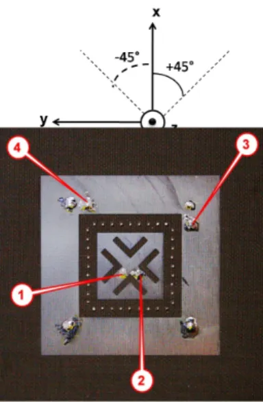
The antenna system, shown in Fig. 1, is composed of a dual-polarized microstrip square patch and a dual-polarized microstrip square ring. L-slots have been etched on the patch to reduce its dimensions [3]. Consequently, the patch can be located in the ring's center in order to obtain a compact structure. Because of slot locations, linear polarizations of the patch antenna are at +/-45°.
Labels F1 to F4 indicate the coaxial feeding points. F1 and
F2 feed respectively the TM10 and TM01 modes of the patch
and F3 and F4 feed respectively the TM21 and TM12 modes
of the ring. Thanks to the dual-polarization behavior of the structures and since the ring radiates differently from the patch, four different radiation patterns are available simultaneously. So pattern diversity is achieved between the four feeding ports. The whole structure acts as four independent antennas. Use these collocated antennas instead of a system based on classical space diversity enables to reduce MIMO terminal size.
However, a drawback of such a structure is the strong coupling between patch and ring modes, especially between F2 and F3 (S32) and between F1 and F4 (S41). On a
transmitter, the energy coupled between input ports is not radiated and so the radiation efficiency decreases. That is why metallic vias have been inserted between the ring and the patch. By enclosing resonant modes inside their
Collocated microstrip antennas for MIMO
systems with a low mutual coupling using
mode confinement
J. Sarrazin, Student Member, IEEE, Y. Mahé, Member, IEEE, S. Avrillon, Member, IEEE, and S.
Toutain
Four other metallic vias take place on the square-ring to set short-circuit locations (according to TM12 and TM21
modes) in order to help finding the 50Ω feeding points.
Fig. 1 - Microstrip antenna configuration
B. Simulation
The structure has been simulated with Ansoft HFSS. The dimensions are given in Table I (according to the Fig. 1) for a substrate with a relative permittivity εr = 2.55 and a
thickness h = 1.58 mm. The distance between each via is lvia = 2 mm which corresponds approximately to λg/18 (with
λg, the guided wavelength). Their influence is studied by
comparing the performances of the structure with and without vias. By enclosing patch and ring modes respectively, vias decrease the coupling between them. Their effects on the ring return loss can be neglected whereas they shift slightly the patch resonance frequency. This effect is compensated by a small variations of the slot length in order to keep the patch resonance frequency identical in both cases (lm = 5.22 mm for the structure with
vias and lm = 5.38 mm for the structure without via).
TABLEI
PARAMETER VALUES OF THE ANTENNA STRUCTURE
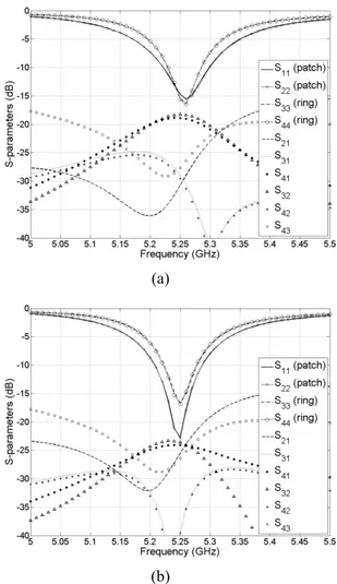
Simulated results are represented in Fig. 2. S-parameters are given for the structure without decoupling via (Fig. 2a) and with decoupling vias (Fig. 2b). In both cases, return loss results show that the two patch modes and the two ring modes resonate around 5.25 GHz with a -10 dB bandwidth of respectively Δf = 1.6% and Δf = 1%.
Without via, strongest couplings occur between input ports F2 and F3 (S32) and F1 and F4 (S41) with levels about -18 dB.
In Fig. 2b, metallic vias have been inserted in order to
5.5 dB improvement has been obtained thanks to vias.
(a)
(b)
Fig. 2 - Simulated S-parameters (a) without decoupling via and (b) with decoupling vias
III. FABRICATIONANDMEASUREMENTS
To prove the concept, the collocated antenna system has been built on a Teflon substrate (εr = 2.55) with the same
dimensions as in simulation (see Table I). The prototype includes the decoupling vias and a picture is shown in Fig. 3.
Parameter Value Parameter Value
εr 2.55 lvia 2 mm h 1.58 mm d1 4.42 mm W1 39.5 mm d2 2.7 mm W2 22.6 mm S 2.5 mm W3 14.5 mm wm 1 mm W4 26.44 mm l
m 5.38 mm (wo. vias)5.22 mm (w. vias)
Fig. 3 - Picture of the prototype with the four input ports
Measured S-parameters are shown in Fig. 4. Ring modes resonate at 5.22 GHz (S33 and S44) and patch modes
at 5.2 GHz (S11 and S22). The coupling is a little bit higher
than the simulation results but still lower than -20 dB.
Fig. 4 - Measured S-parameters of the built antenna with decoupling vias
Measured radiation patterns for the four modes are given in Fig. 5 and Fig. 6. Co-polarization and cross-polarization planes are given according to the +/- 45° polarization of the square patch. Patch modes are nearly orthogonal between them as well as ring modes. Furthermore, patch and ring radiation patterns have different shapes which means that pattern diversity is achieved. In order to quantify the pattern diversity capability, channel capacity measurements have been conducted as it is described in the following section.
TM10 mode (input port F1) TM01 mode (input port F2)
Fig. 5 – Measured radiation patterns of patch modes TM21 mode (input port F3) TM12 mode (input port F4)
Fig. 6 - Measured radiation patterns of ring modes
IV. MIMOCHANNELCAPACITYRESULTS
To determine the channel capacity with the proposed collocated antennas, we performed an experimental 4x4 MIMO channel measurement as it is described in [5]. By using a vector network analyzer, channel responses have been measured between the multiple transmission antennas and the multiple reception antennas. Since the analyzer has only two input ports, two switches 4-ways (one for TX and one for RX) have been used to feed successively each antenna. Non fed antennas are terminated by matched loads to not disturb the behavior of the system. Measurements have been performed in our laboratory which is a rich scattering environment. To ensure the channel is stationary, data were obtained while nobody was in the room. The measurement bandwidth represents a typical WiFi channel: 22 MHz around 5.22 GHz (with 101 frequency sample points).
For all the results, the MIMO channel is averaged over 20 snapshots in order to reduce the measurement noise. The channel is then normalized with the Frobenius norm and the capacity is determined with the following expression:
( )
⎟⎟ ⎠ ⎞ ⎜ ⎜ ⎝ ⎛ ⎥ ⎦ ⎤ ⎢ ⎣ ⎡ + = H t r N N H H I C log2 det rρ
with ρr the signal-to-noise ratio at the reception, Nt the
number of transmission antennas, H the MIMO channel matrix ((.)H denotes the Hermitian transposition) and I
Nr the
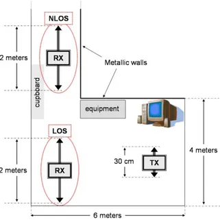
identity matrix. Measurements have been conducted for 10 locations of the receiver and 2 of the transmitter for a LOS and a NLOS environment, as shown in Fig. 7. The distance between TX and RX is about 3.5 meters for the LOS case and 4.5 meters for the NLOS case. Capacity results are determined from an average of these 20 relative TX/RX
Results for LOS and NLOS conditions are given in Fig. 8a and Fig. 8b, respectively. For both environments, the transmitter is constituted of four monopoles spaced by a wavelength. The receiver is successively constituted of four monopoles spaced by a half-wavelength, four monopoles spaced by a wavelength and the proposed collocated antenna system. Capacity results of these three receivers are compared. Furthermore, simulated capacities of independent and identically distributed (i.i.d.) SISO, MIMO 3x3 and MIMO 4x4 channels are also given.
Fig. 7 - Room of measurements
For the LOS environment (Fig. 8a), we note that the capacity of the four monopoles spaced by a wavelength slightly lead to a higher capacity than those spaced by a half-wavelength. Approximately the same difference can be observed between the half-wavelength spaced monopoles and the collocated system. However, capacities provided by the three tested antenna systems are quite equivalent and are between the i.i.d. MIMO 3x3 and 4x4 channel results. In the NLOS environment (Fig. 8b), results are quite similar. Capacities of the three tested antenna systems are also very close together.
For both cases, the collocated antenna system provides performances which are close to those available with monopoles. Furthermore, the proposed system is smaller than four spaced monopoles and is more suitable for integration on a terminal. Consequently, we can conclude that proposed collocated antennas are well-suited in order to reduce MIMO communication system sizes without decreasing their performances.
(a)
(b)
Fig. 8 - Measured capacities at 5.22 GHz for (a) LOS environment and (b) NLOS environment
V. CONCLUSION
A collocated antenna system has been proposed in order to reduce sizes of MIMO devices. By combining microstrip square-ring and square-patch antennas on their both polarizations, radiation diversity is achieved. This allows obtaining a compact structure which is able to transmit or receive four uncorrelated signals. MIMO channel measurements have demonstrated the potential of such a system to be used instead of classical space diversity antennas.
VI. REFERENCES
[1] A.S. Konanur et Al., “Increasing wireless channel capacity through MIMO systems employing co-located antennas”, IEEE Trans. on Microwave Theory
and Techniques, vol. 53, no. 6, pp. 1837-1844, June
2005
[2] J. Sarrazin, Y. Mahé, S. Avrillon and S. Toutain, “Four co-located antennas for MIMO systems with a low mutual coupling using mode confinement”, IEEE
Antennas and Propagation Symposium, July 2008
[3] G.S. Row, S.H. Yeh and K.L. Wong, “Compact dual-polarized microstrip antennas”, Microwave Opt.
Technol. Lett., vol. 27, pp. 284-287, Nov. 2000
[4] J.-M. Kim and J. Yook, “A parallel-plate-mode suppressed meander slot antenna with
plated-through-holes”, IEEE Antennas and Wireless Propagation
Letters, vol. 4, pp. 118-120, 2005
[5] H. Nishimoto, Y. Ogawa, T. Nishimura and T. Ohgane, “Measurement-based performance evaluation of MIMO spatial multiplexing in a Multipath-rich indoor environment”, IEEE Trans. on Antennas and