HAL Id: hal-02114819
https://hal.archives-ouvertes.fr/hal-02114819
Submitted on 3 May 2019
HAL is a multi-disciplinary open access
archive for the deposit and dissemination of
sci-entific research documents, whether they are
pub-lished or not. The documents may come from
teaching and research institutions in France or
abroad, or from public or private research centers.
L’archive ouverte pluridisciplinaire HAL, est
destinée au dépôt et à la diffusion de documents
scientifiques de niveau recherche, publiés ou non,
émanant des établissements d’enseignement et de
recherche français ou étrangers, des laboratoires
publics ou privés.
for Medical Information Security
William Puech, Gouenou Coatrieux
To cite this version:
William Puech, Gouenou Coatrieux. Hybrid Coding: Encryption-Watermarking-Compression for
Medical Information Security. Amine Naït-Ali; Christine Cavaro-Ménard. Compression of Biomedical
Images and Signals, ISTE, pp.247-276, 2008, 9781848210288. �10.1002/9780470611159.ch10�.
�hal-02114819�
Hybrid Coding:
Encryption-watermarking-compression
for Medical Information Security
10.1. Introduction
Nowadays, more and more digital images are being sent over computer networks. The works presented in this chapter show how encryption and watermarking algorithms provide security to medical imagery. In order to do this, the images can be encrypted in their source codes in order to apply this functionality at application level. In this way, the encryption and watermarking of images occurs at software level. We can therefore guarantee the protection of a medical image during transmission, and also once this digital data is archived. The subsequent challenge is to ensure that such coding withstands severe treatment such as compression. The quantity of information (entropy) to be sent greatly increases from the original image to the encrypted image. In the case of certain types of medical imagery, large homogenous zones appear. These zones affect the effectiveness of the coding algorithms. Nevertheless, these homogenous zones, useless for any diagnosis, can be safely used for the watermarking of medical images.
When a physician receives a visit from a patient, he often requires a specialist opinion before giving a diagnosis. One possible solution is to send images of the patient, along with a specialist report, over a computer network. Nevertheless, computer networks are complex and espionage is a potential risk. We are therefore
faced with a real security problem when sending data. For ethical reasons, medical imagery cannot be sent when such a risk is present, and has to be better protected. Encryption is the best form of protection in cases such as this. Many different techniques for the encryption of text already exist. Since ancient times, humanity has attempted to encode secret messages in order to elude wandering, indiscreet eyes and ears. The most basic forays into this field relied upon algorithms which allowed coding and decoding. Over time, the notion of a key arose. Today, encryption systems rely upon algorithms which are available to the world at large, and it is the key, a code which remains confidential, which allows for the encryption and decryption of the message [KER 83].
In section 10.2 we will show how essential it is to ensure the security of medical imagery and data. Then in section 10.3 we will present the standard encryption algorithms and will show, in section 10.4, how these can be suited to medical imagery. Finally, in section 10.5, we will show how it is possible to hide data in these images, while retaining a high level of image quality.
10.2. Protection of medical imagery and data
Developments in techniques for the treatment, sharing and communication of medical imagery, and medical information in general, go hand in hand with an increased risk for information in a digital format. Medical information in general is chiefly made up of the results of analyses, clinical and para-clinical examinations, and personal information [DUS 97]. Possibilities for distant access and the sending of information have increased the chances of leaks, losses and alterations of the information which are also greater due to, or even assisted by, the availability of network surveillance tools and advanced editing tools such as imagery software.
However, it is the consequences brought about by the occurrence of these risks which create the need for the protection of medical information. These consequences, which are not negligible, concern an individual and his health, and the privacy of these. This is why many countries attribute legal and ethical weight to this question; acknowledging patient rights and thereby obliging medical professionals and health centers to ensure the protection of the data in their possession.
10.2.1. Legislation and patient rights
Legislation and the medical ethics code accompany the technical evolution and, through a number of important legal texts, recognize patient rights. The first, and best-known, refers specifically to the patient-doctor relationship and concerns
medical confidentiality. The guaranteed confidentiality of any information which a patient may exchange with anyone in the healthcare system allows a relationship based on trust to be established. This relationship also enables the healthcare professional to judge the patient’s situation as effectively as possible.
The computerization of the health system and the possibilities this offers both in terms of the mechanization of treatments and the sharing of information, has resulted in the widening of the legal coverage of the field, and new laws must be taken into account by healthcare professionals; in particular in France law no. 78-17
of 6th January 1978 – known as the “information technology and freedom law”,
complemented by the law of 1st January 1994, the “law pertaining to the treatment of
data, with regard to health sector research”. In France, the CNIL (National Commission on IT and Liberty) has the task of ensuring that these laws are respected (articles 6 to 13). These laws, aside from the collection of information, give every citizen – and therefore every patient – the right to control the use of information which concerns them personally [DUC 96]. In particular, the patient has a right to security, and article 29 states that it is the responsibility of the healthcare professional to take “every possible measure to ensure the security of the information, and particularly to ensure that it is not altered, damaged or allowed to reach unauthorized third parties”. If this law is not respected, legal measures can be taken (article 226-17 of the penal code). From a practical and technical point of view, working groups such as that put in place by the European Standards Committee TC/251 Medical Information (Working Group III), show that in order for this criteria to be met, the following must be achieved [ALL 94]:
- the confidentiality of the data, by restricting access to the rightful owners (the patient and the healthcare professionals dealing with his case, considering the collaborative nature of medical practice and derogations allowed by the law);
- the integrity of the information, ensuring that the information has not been modified by anyone but a qualified person in agreed conditions;
- the availability, which guarantees access to the data within standard procedure.
10.2.2. A wide range of protection measures
Whatever the nature of the information, we can distinguish three types of protection measure for data stored, treated and sent using an information system: the legislation, security policies and protection mechanisms. These measures should be considered together in order to meet the AIC (Availability, Integrity and Confidentiality) requirements for the data. Nevertheless, these measures vary amongst themselves according to the target information system and its context. We can draw a difference between the systems installed at a single practitioner’s
practice from those of a health center – whether fitted or not with communication applications such as telemedicine applications.
The first type of legal measure aims to discourage those who would infringe either deliberately or accidentally the confidentiality, integrity and availability of data and information systems (e.g. in France, the Godfrain Law no. 88-19 of 05/01/1998). However, such measures are only effective if it is possible to detect the intrusion of a third party into an information system. A healthcare establishment’s security policy aims to set the strategy for the implementation and upkeep of the highest security level. This policy decides upon, among other things, various protocols for the usage of information and systems, taking into consideration the risks to the AIC of the data and the specific roles of the various parties present in the hospital framework. Most notably, it is up to the security policy to decide and regulate the use of protection tools and mechanisms. These physical or logical mechanisms are numerous and entail more or less complex procedures to be carried out. The first group deals with the physical protection of the material (restricted access to the rooms concerned, steps to avoid damage from the elements, to prevent theft, etc.), and the second group is integrated into the information systems. The tools which we will study in this chapter fall into this second category; cryptographic tools (encoding and digital signatures) and the watermarking of images. Among the other logic protection mechanisms we can include [COA 03]:
– access control which includes a policy determining those with a right to the information or access to the workings of a system, and technical solutions for the identification of users, such as chip-card systems, or biometric screening;
– firewalls whose primary task is to control access to the system both at the entry and exit stages, as soon as the system is connected to a network;
– antivirus systems;
– auditing which allows us to keep a record of the access made to the information by users or computer programs.
It is important to highlight the fact that these mechanisms are complementary, and are therefore to be used alongside one another. Additionally, some of these mechanisms, such as access restriction, rely upon cryptographic systems. The watermarking of images has come into use more recently, and has found its place among the range of tools on offer. Before discussing these techniques, let us return to medical imagery. These images are often produced, stored and communicated with the DICOM standard described in Chapter 4. This standard is more than a simple storage format, and includes very specific “profiles” or procedures, with the aim of guaranteeing the AIC requirements for storage and exchange between DICOM-compatible systems. These profiles are based on cryptographic mechanisms.
10.3. Basics of encryption algorithms 10.3.1. Encryption algorithm classification
There are four key objectives for the encryption of digital data:
- confidentiality or masking of the data – the most widely-used characteristic – which aims to render the cryptogram unintelligible to anyone without the key;
- authentication allows the sender to sign his message, thereby leaving the recipient in no doubt as to who sent the message;
- integrity serves to assure the recipient that the message content has not been altered or manipulated since its creation;
- non-repudiation is the guarantee that neither of the parties involved will be able to deny having sent or received the message;
The most important objective for medical imagery is, naturally, the first: confidentiality. However, the notion of integrity described in section 10.2., as well as the two others, is also important in the protection of medical imagery.
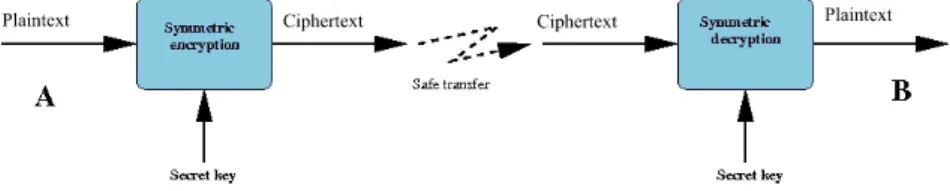
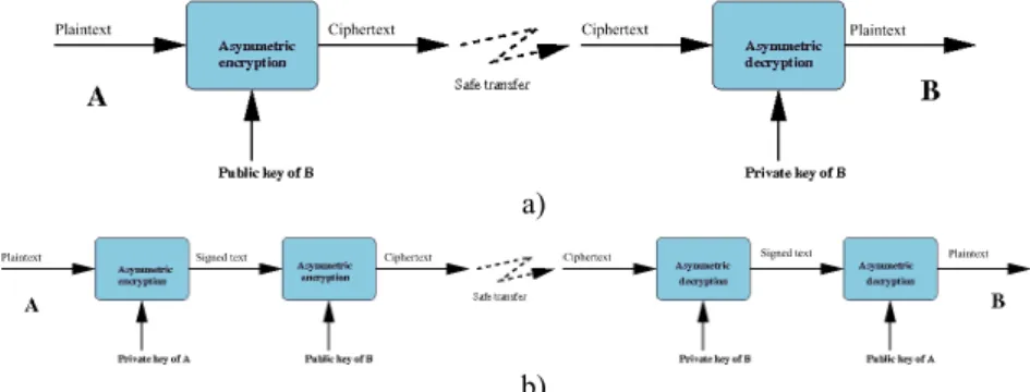
Encryption algorithms can be separated out according to various characteristics: the systems with a secret key (symmetric systems), illustrated in Figure 10.1, and those with public and private keys (asymmetric systems), shown in Figure 10.2 [DIF 76], [STI 96]. The secret key systems are those which allow encryption and decryption with the same key. It goes without saying that the sender and the recipient must beforehand have exchanged the secret of this key, via a secure method of communication. The systems using a public or asymmetric key can overcome this step by using one key to encrypt the data, and another to decrypt it. Each person should possess a pair of keys, one of which is confidential (the private key) and the other known by the world at large (the public key). In order to write to B, all that needs to happen is for the message to be encoded with the public key of B, which is known. Upon reception, only B will be able to decrypt the message with his private key. In this section, we present several data encryption systems; symmetric block systems, with a secret key (DES and AES), an asymmetric block system, with a public key (RSA); and a stream cipher system.
a)
b)
Figure 10.2. a) Basis of asymmetric encryption; b) double asymmetric encryption, guaranteeing confidentiality and authenticity
10.3.2. The DES encryption algorithm
The DES (Data Encryption Standard) algorithm is one of the standard systems for block encryption (Figure 10.1). Its security relies entirely upon the secrecy of the key, as the algorithm is public. In 1974, the DES algorithm became the first standard of modern cryptography [SCH 95]. The DES algorithm is based on 16 rounds, (a collection of stages repeated 16 times) during which a data block of 64 bits is mixed with the key K, which is also encoded on 64 bits. At each of these rounds, a sub-key
ki is calculated from the initial key K (this sub-key will serve to mix up the block’s
bits). Once the 16 sub-keys have been generated from the secret key, it is possible to cipher (or decipher) a 64-bit block of data. The process begins with an initial permutation (IP) which changes the order of the bits in the initial block, before
splitting the result into two blocks of 32 bits, L0 and R0 . Once the 16 rounds have
been passed, and before giving the result, a final permutation must be applied to the block. This permutation is no more than the inversion of the IP. For the decryption, the process is the same, apart from the fact that the sub-keys are used in the opposite order.
Today, even if the algorithm is still respected, it suffers somewhat from the fact that the length of its key is limited to 64 bits. The current performance-levels of machines, in terms of computational time, make the DES breakable. The so-called
brutal attack involves trying all of the 264 potential keys, and is nowadays feasible
for big calculators. A solution has been produced to increase the security level: it is called the triple-DES. The triple DES involves the encryption of the entry block three times with three different keys: K1, K2 and K3. There are several variations, but
in general the first and third operations are encryption operations, whereas the
second is a decryption operation. Often, we choose that K1 = K3, which does not
allow the whole key to go beyond 128 bits.
Comment [RE1]: Should this
10.3.3. The AES encryption algorithm
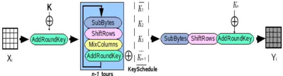
The AES (Advanced Encryption Standard) algorithm is the standard system for block encryption and aims to replace the DES which has become vulnerable. The number of rounds in the AES algorithm depends upon the size of the key and the size of the data blocks. For example, the number of rounds is 9 if the blocks and the key have a length of 128 bits. To encrypt a block of data with AES (Figure 10.3), we must first of all complete a stage called “AddRoundKey”, which involves applying an “exclusive OR” (XOR) between a sub-key and the block. After this, we enter into the operation of a round. Each regular round operation involves four steps. The first step is called “SubByte”, where each byte of the block is replaced by another value created by an S-box. The second step is called “ShiftRow”, where the rows are cyclically moved with different offsets. In the third step, called “MixColumn”, each
column is treated as a polynomial which is multiplied with a matrix in the GF(28)
(Galois Field). The final step of a round is again called “AddRoundKey”, which is a simple XOR between the given data and the sub-key of the given round. The AES algorithm carries out a final additional stage made up of the “SubByte”, “ShiftRow”, and “AddRoundKey” stages before producing the final encryption. The process applied to the “plaintext” (original data) is independent of that applied to the secret key, with the latter being called “KeySchedule”. This is made-up of two
components: the “KeyExpansion” and the “RoundKeySelection” [DAE 02],
[AES 01].
Figure 10.3. General AES scheme
The AES algorithm can support the following encryption modes: ECB, CBC, OFB, CFB, CTR, etc. The ECB (Electronic CodeBook) mode is that of the standard AES algorithm as described in document 197 of the FIPS (Federal Information Processing Standards). From a binary sequence X1, X2,..., Xn of plaintext blocks, each
Xi is encrypted with the same secret key k in order to produce the coded blocks Y1,
Y2,.., Yn. The CBC (Cipher Block Chaining) mode adds a step before the encryption.
Each encrypted block Yi is added by an XOR to the new current block Xi+1 before
being encrypted with the key k. An initialization vector (IV) is used for the first iteration. In fact, all the modes apart from ECB need an IV. In the CFB (Cipher
FeedBack) mode, IV = Y0 . The dynamic key (or key stream) Zi is generated by Zi =
Ek(Yi−1), i > 1, and the encrypted block is produced by Yi = Xi⊕Zi. In the OFB
(Output FeedBack) mode, as in the CFB, Yi = Xi⊕Zi but VI = Z0 and Zi = Ek(Zi−1), i >
1. The input data is encrypted after an XOR with the output Zi . The CTR (counter)
mode has characteristics very similar to those of OFB, but it also allows for a random access for the decryption. It generates the following dynamic key by encryption of the successive value provided by a counter. This counter can be a simple function which produces a pseudo-random sequence. In this mode, the output of the counter is the entry of the AES algorithm.
Even if AES is a block encryption algorithm, the OFB, CFB, and CTR modes operate like stream ciphers. These modes require no particular measure concerning the length of messages. Each mode has its own advantages and disadvantages. In the
ECB and OFB modes, for example, any change in the plaintext Xi results in a
modification in the corresponding encrypted block Yi, but the other encrypted blocks
are not affected. On the other hand, if a plaintext Xi is changed in the CBC and CFB
modes, then Yi and the new encrypted blocks will be affected. These properties mean
that the CBC and CFB modes are useful for authentication, and the ECB and OFB modes treat each block separately. As a result, we can note that the OFB mode does not propagate noise, whereas the CFB mode does.
10.3.4. Asymmetric block system: RSA
The RSA algorithm is the most widely-used asymmetric system. Its security relies upon the slowness of current computers for factorizing very large numbers into products of prime numbers [SCH 95], [SHA 78]. Let p and q be two very large distinct prime numbers, and n a very large number which is the product of p and q. We write as φ(n) the Euler function in n in order to have numbers smaller than n and first with n, with φ(n) = (p-1)(q-1).
The public key/private key pair will reside in two numbers, d and e associated with n. e is first calculated randomly between 2 and φ(n) and must be prime with
φ(n). The (n,e) pair is the public key. Then d is calculated such as d = e−1mod(n).
The extended Euclidian algorithm allows the calculation of this inversion, even in the case of very large numbers. The (n,d) pair is the private key. The use of keys for the encryption and the decryption is as follows. If m is the original message (lower than n, otherwise it is cut), we encrypt it with the public key (n,e) raising it to the
power e, modulo n. We obtain the encrypted message m’ = memod(n). For the
decryption, we need the private key second key (n,d). By raising the encrypted message to the power d modulo n and as d and e are inverted modulo n, we obtain:
m n m n n m n
m')d mod( )=( emod( ))d mod( )= edmod( )=
( [10.1]
For example, if Bob wishes to send a message to Alice, he converts his message into numbers, and cuts the message into blocks of a size smaller than n. For each
block mi, using Alice’s public key, Bob calculates and codes the block as follows:
), mod(n
m
ci = ie [10.2]
with i, the position of the block in the text, i ∈ [1,N], if N is the number of blocks. Alice, with her private key, can then decrypt the message by doing:
) mod(n
c
mi = id [10.3]
Thus, the RSA method differs from the symmetric encryption systems in that it uses two different keys for encryption and decryption (Figure 10.2). One of these two keys, the public key is meant to be known to everyone, and the other, the private key, is known to only one individual. The RSA algorithm can allow either encryption with a public key, in which case only the recipient will be able to decrypt the message with his private key, or encryption with one’s own private key (signature). In this case, everyone can read the message thanks to the public key, but the sender was able to sign the message, since he is potentially the only person who could have encrypted it with his private key. A double encryption, using public key/private key therefore allows combining a signature with confidentiality (Figure 10.2b).
Unfortunately, RSA is a very slow algorithm; much slower than any symmetric system, and even more so because the numbers used are very large. Moreover, it is
easily breakable today, even for 512 bits3 numbers. It is currently advisable to use
keys 1,024 bits long. It is therefore preferable to use it to send a secret key in a secure way, which will allow the message to be decrypted, with AES faster than RSA.
10.3.5. Algorithms for stream ciphering
Algorithms for stream ciphering can be defined as algorithms for encryption by block, where each block has a unitary dimension (1 bit or 1 byte) or is relatively small. Their main advantages are their very high speed and their ability to change each symbol of the plaintext. With a stream cipher algorithm, it is possible to encrypt each character of the plaintext separately, using an encryption function
which varies each time (these algorithms therefore need memories). In general, algorithms for stream cipher are made up of two stages: the generation of a dynamic key (key stream) and the encryption output function using the dynamic key.
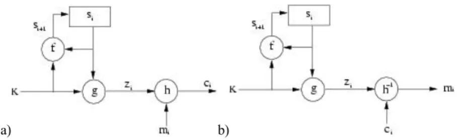
When the dynamic key is created independently of the plaintext and the ciphertext, the stream cipher algorithm is synchronous. With a stream cipher algorithm, the sender and receiver have to synchronize using the same key at the same position. Synchronous stream ciphers are used in environments where error is common, because they have the advantage of not propagating errors [GUI 02]. Concerning active attacks, such as the insertion, deletion or copying of digits of the ciphertext by an active adversary, these attacks immediately result in a loss of synchronization. The encryption process of a synchronous stream cipher is described in Figure 10.4, where f() is the function which determines the following state, g() is the function generating the dynamic key, and h() is the encryption output function:
⎪ ⎩ ⎪ ⎨ ⎧ = = = + ) , ( ) , ( ) , ( 1 i i i i i i i m z h c s K g z s K f s , [10.4] where K is the key, si, mi, ci and zi are respectively the ith state, plaintext, ciphertext
and dynamic key. The decryption process is shown in Figure 10.4.
a) b)
Figure 10.4. Synchronous stream cipher: a) encryption, b) decryption on the right
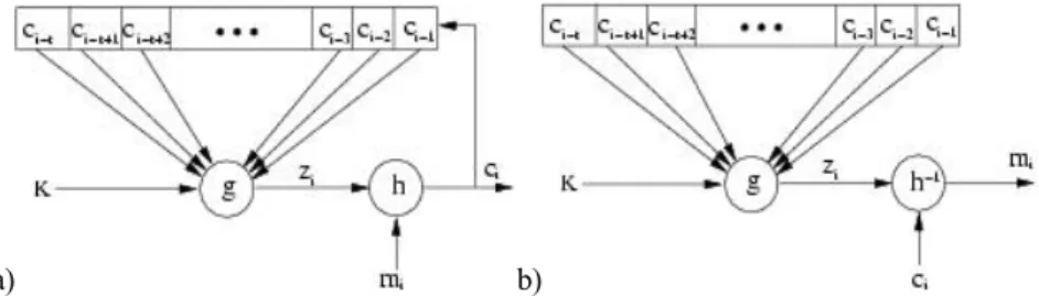
When the dynamic key is generated from the key and a certain number of previous ciphertext, the stream cipher algorithm is called asynchronous, also known as a self-synchronous stream cipher. The propagation of errors is limited to the size of the memory. If digits of the ciphertext are erased or added to, the receiver is able to resynchronize himself with the sender, by using the memory. As for active attacks, if an active adversary modifies any part of the digits of the ciphertext, the receiver will be able to detect this attack. The encryption process of an asynchronous stream cipher is described in Figure 10.5, where g() is the function which generates the dynamic key, and h() the encryption output function:
⎩ ⎨ ⎧ = = − −+ − − ) , ( ) , ,..., , , ( 1 2 1 i i i i i t i t i i m z h c c c c c K g z , [10.5] where K is the key, mi, ci and zi are respectively the ith plaintext, the ciphertext, and
the dynamic key. We can observe in equations [10.5] that the dynamic key depends upon the previous t digits of the ciphertext. In order to resist statistical attacks, function g(), which generates the dynamic key, must produce a wide period sequence, with good statistical properties which can be called pseudo-random binary sequences. The decryption process is illustrated Figure 10.5.
a) b)
Figure 10.5. Asynchronous stream cipher: a) encryption, b) decryption on the right
10.4. Medical image encryption
In this section, we will demonstrate how it is possible to apply the above algorithms to medical images in the grey level. In the case of 1D medical signal, the standard coding algorithms can be applied directly. However, because of the bidimensional characteristic of images, and their size, these standard algorithms must be modified in order to be used effectively on medical images. The aim of image encryption is to obtain an image in the same format and without increasing the size above that of the original image. The encryption of images is considered as a source coding to process this functionality at the application level. Due to this, if a user does not possess the key, he does at least have access to an image in a known format. By carrying the encryption step up to the application level, it is possible to proceed, for example, towards a region of interest of the image. In the case of large images, it therefore becomes unnecessary to decrypt the whole image if we only want to view one particular area. The compression stage should also be taken into account during the image encryption stage.
10.4.1. Image block encryption
In the case of block encryption, the length of the blocks is fixed, and varies from 64 bits (8 pixels) to 192 bits (24 pixels). From the bidimensional information of an image, several pixel grouping solutions are possible. With the aim of withstanding a downstream compression as well as possible, or compressing at the same time as coding, it is useful to group the pixels with their nearest neighbours (in rows, columns, or blocks). Each block of pixels is encrypted separately. The encrypted block obtained will then come to replace the original block in the image. In this chapter, the route taken for scanning the blocks is carried out only in a linear manner (scan line). Manniccam and Bourbakis show that it is often more useful to use other types of scanning (spirals, zigzags etc.) in order to combine encryption with lossless compression [MAN 01], [MAN 04].
10.4.2. Coding images by asynchronous stream cipher
In this section, we present an asynchronous stream cipher algorithm which is applied to images. Let K be a key of length k bits bi, K = b1b2...bk. The unit of
encryption is the pixel (1 byte). The method lies in the fact that for each pixel of the image, the encryption depends upon the original pixel, the value of the key K, and the k/2pixels previously encrypted. To use equations [10.5], we have t = k/2. For
each pixel pi of the original image, we calculate the value of the pixel p’i of the
encrypted image using the following equation:
⎪ ⎩ ⎪ ⎨ ⎧ + = ⎟ ⎟ ⎠ ⎞ ⎜ ⎜ ⎝ ⎛ =
∑
= − ) 256 mod( ) ( ' ) 256 mod( ' 2 1 i i i k j j i j i p z p p z α [10.6]with i ∈ [0,…,N−1] where N is the number of pixels in the image, k is the length of
the key with k ∈ [1,N], and αj is a sequence of k/2 coefficients generated from the
secret key K [PUE 01a].
The encryption principle is the same as that shown in Figure 10.5. Equations [10.6] have a recurrence of the order k/2, corresponding to half of the length of the
key [PUE 01b]. Coefficients αj are integer values included between -2 and +2 such
as:
{ }
⎩ ⎨ ⎧ = ± = ∈ − = 3 si 2 2 , 1 , 0 si 1 j j j j j β α β β α [10.7]with βj = 2b2j-1+b2j, where b2j-1 and b2j are two consecutive bits of the secret key K.
In addition, the probability density of the αj must be uniform in order to reduce the
transmission errors during the decryption stage. The sign in front of the coefficients equal to 2 depends on coefficients αj in order to obtain:
0 2 1 2 1 ≈
∑
= k j j k α [10.8] Considering that the encryption of a pixel is based on the k/2 pixels previouslyencrypted, we cannot encrypt the k/2 first pixels of the image. It is necessary to associate the αi coefficients with a sequence of k/2 virtual encrypted pixels p’-i, for i
∈ [1,…,k/2]. This pixel sequence corresponds to an initialization vector (IV). In consequence, an IV is coded in the key: k/2 values of virtual pixels which allow us to encrypt the k/2 first pixels of the image as though they had predecessors. The length k of the key K must be big enough to guarantee maximum security. Equation [10.9] presents the decryption procedure. In the decryption procedure, we must apply the process in reverse. We can note that the function which generates the dynamic key is the same as equation [10.6]:
⎪ ⎩ ⎪ ⎨ ⎧ − = ⎟ ⎟ ⎠ ⎞ ⎜ ⎜ ⎝ ⎛ =
∑
= − ) 256 mod( ) ' ( ) 256 mod( ' 2 1 i i i k j j i j i z p p p z α [10.9]10.4.3. Applying encryption to medical images
Starting out with the image in Figure 10.6a, we have applied the DES algorithm by blocks of 8 pixels in a row, with a 64-bit key to obtain the image in Figure 10.6c. We can observe the appearance of textures (Figures 10.6c-e). The reason for this phenomenon lies in the appearance of large homogenous zones (black in this case) on the medical images. At the level of the histograms (Figures 10.6d-f), we observe the strong presence of grey levels corresponding to the encryption of the grey levels of the homogenous zones. The encryption is therefore very poor for two reasons: firstly because it is easy to guess the nature of the medical image (an ultrasound), but mainly because the availability of the value of the plaintext block (the pixels were all black), and after encryption (the grey levels dominating in the encrypted image) is a precious clue for cryptanalysts. Block encryption algorithms therefore present us with serious problems when images contain homogenous zones.
a) c) e)
b) d) f)
Figure 10.6. a) Medical ultrasound image (442KB), with large homogenous zones, encrypted image; c) encrypted by DES algorithm (block of 8 pixels with a 64-bit key);
e) by AES algorithm (block of 8 pixels with a 128-bit key); b), d) and f) histograms
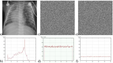
From the original image, Figure 10.7a (396x400 pixels), we have applied a stream cipher algorithm with a 128-bit key. Figure 10.7c illustrates the values
obtained for the dynamic key zi generated by equation [10.6]. We can note that
(Figure 10.7d) the probability of the appearance of each value is practically equal. Consequently the function generating the dynamic key g() produces a sequence with a large period and good statistical properties. From equations [10.6], we obtain an encrypted image (Figure 10.7e), and we can see that the initial image is no longer visible at all. By comparing the histogram of the initial image (Figure 10.7b), with the histogram of the encrypted image (Figure 10.7f), we can see that the density of probability of the grey levels is more or less identical. As a result, the entropies of the encrypted images are very high (around 8 bits/pixel).
a) c) e)
b) d) f)
Figure 10.7. a) Original image, b) histogram of original image, c) image of the dynamic key zi, d) histogram of the values of the dynamic key zi,
e) final encrypted image with the coding algorithm by asynchronous stream cipher, with a 128-bit key, f) histogram of the encrypted image
The stream cipher method has one major advantage over other encryption systems used in medical imagery. As the result of the encryption of the previous pixels is taken into account for each pixel to be encrypted, the problem of homogenous zones is solved. We are no longer dealing with block encryption systems, where two identical original blocks give the same encrypted block. We can observe that whatever the type of image with or without homogenous zones, no texture appears in the encrypted images. In conclusion, in the case of stream cipher algorithms, the homogenous zones are no longer visible either in the image or the histogram. The stream cipher method also carries another advantage: as the calculations which make it up are small in number, it proves to be very quick; even more so than AES. For example, a 7 MB image is encrypted (or decrypted) in 5 s with a standard PC, rather than the 15 s required for algorithms using a block encryption.
10.4.4. Selective encryption of medical images
Another way to ensure confidentiality is to adapt the protection level according to the application and the time available. It is in this second approach that we find selective encryption where users can apply a security level which can vary according to requirements [NOR 03]. Many applications can be protected with only selective
encryption; the images are therefore partially visible, without revealing all the information. Selective encryption can be useful in the case of medical images taken with a medical device and needing to be sent over a network in order to be diagnosed remotely. Furthermore, the device used for capturing medical images may be located in an ambulance or some other mobile vehicle, and in this case the transmission is carried out via the intermediary of a wireless network. Due to the vital nature of these images, they must be sent quickly and safely, and in this case a selective encryption seems to be the best solution (in terms of the time/security ratio).
In this section we present a selective encryption method for medical images compressed with JPEG [PUE 06]. This method is based on the AES algorithm, using the OFB (Output Feedback Block) mode in the Huffman coding stage of the JPEG algorithm. The combination of selective encryption and compression allows us to save time in the calculation and to retain the JPEG format and initial compression rate. In terms of security, selective encryption guarantees a certain level of confidentiality. Many different selective encryption methods have been developed for images coded by DCT. Tang [TAN 96] proposes a technique called zigzag permutation, which can be applied to videos or images. Although his method offers a good level of confidentiality, it does decrease the compression rate. [DRO 02] describes a technique which encrypts a selected number of AC coefficients; the DC coefficients are not encrypted as they carry important visible information and are highly predictable. For this method, the compression rate is constant (compared to compression only) and retains the binary flow format. However, the compression and the encryption are carried out separately, so the method is slower than a simple compression. [FIS 04] presents a method where the data is organized in a binary flow form which can be regulated. Recently, Said has shown the strength of partial encryption methods by testing attacks which use the non-encrypted information of an image alongside a small image [SAI 05].
Let EK(Xi) be the encryption of a block Xi of n bits using the secret key K with the
AES algorithm in OFB mode. In the description of the method, we will suppose that n = 128 and Xi is a non-empty plaintext. Let us suppose that DK(Yi) is the decryption
of a ciphertext Yi using the secret key K. The encryption is applied at the same time
as the entropic coding procedure during the creation of the Huffman vector. The method works in three steps illustrated in Figure 10.8: the construction of the plaintext Xi, the encryption of Xi to create Yi and the substitution of the original
Huffman vector with the encrypted information [ROD 06]. It should be mentioned that these operations are carried out separately for each DCT block quantified.
Figure 10.8. Global overview of the proposed method
To construct the plaintext Xi, we take the non-null AC coefficients of the current
block i accessing the Huffman vector from its end towards its beginning in order to create {HEAD, AMPLITUDE} pairs. From each HEAD we obtain the size of
AMPLITUDE in bits. Only the AMPLITUDES (An, An-1,..., A1) are taken into
account to build vector Xi. The final length of the plaintext LXi depends both on the
homogenity ρ of the block and a given constraint C, with C ∈ {128, 64, 32, 16, 8}
bits. This means that a block with a large ρ will produce a small LXi . The Huffman
vector is processed as long as LXi≤ C and the DC coefficient is not reached. Next,
the padding function is applied, p(j) = 0, where j ∈ { LXi,…, 128}, in order to fill in
the Xi vector with zeros, if necessary.
At the stage where X i is encoded with AES in OFB mode, the dynamic key Zi-1 is
used as a parameter by the AES encryption in order to obtain a new dynamic key Zi.
For the first iteration, the IV is created from the secret key K with the following strategy: the secret key K is used as a seed for a Pseudo Random Number Generator (PRNG). This K is divided into 16 sections of 8 bits each. The PRNG produces 16
random numbers which define the formation order of the IV. Next, each Zi is added
by an XOR with the plaintext Xi to generate the encrypted block Yi.
The final step is the substitution of the initial information with the encrypted information in the Huffman vector. As in the first step (the construction of the
plaintext Xi), the Huffman vector is read backwards, but the coded vector Yi is read
starting from the beginning and moving to the end. Knowing the length, in bits, of
each AMPLITUDE (An, An-1,..., A1), these sections are cut in Yi to replace the
AMPLITUDE in the Huffman vector. The total quantity of bits must be LXi. This
procedure is carried out for each block. Any homogenous blocks are only slightly coded, or not at all. The use of the OFB method for coding allows for the generation
added by an XOR to the ciphertext Yi in order to regenerate the plaintext Xi. The
vector resulting from the plaintext Xi is cut into sections from the end to the
beginning in order to replace the AMPLITUDES in the Huffman code to generate the Huffman vector. This method is applied to dozens of medical images in the grey level (see example in Figure 10.9).
a) b) c)
Figure 10.9. From left to right: original medical image of a colon cancer, 320x496 pixels; encrypted image for C = 128; encrypted image for C=8
The JPEG algorithm has been used with the online sequential coding system for a quality factor (QF) of 100%. Five values were applied for constraint C (128, 64, 32, 16, and 8). For the encryption, the AES algorithm was used with the stream cipher mode OFB with a key of 128 bits in length. The original medical image of 320x496 pixels (Figure 10.9), compressed so that all the encrypted images are of the same size: 43.4 KB. The encrypted coefficients are distributed in the 2480 8x8 blocks in the image. This means that there are no totally homogenous blocks. For C = 128, maximum of 128 bits encrypted per block, 26,289 AC coefficients have been encrypted, which is an average of 33 encrypted bits per block. The percentage of encrypted bits in the image as a whole is 22.99%. That means, in the spatial domain, 136,038 modified pixels, which means 85.71% of the coded pixels. The PSNR is of 23.39 dB for C = 128. For C = 8, the quantities of AC coefficients and bits encrypted are respectively 6,111 and 16,765. The percentage of encrypted bits in terms of the whole image is 4.7%. This constraint gives a number of modified pixels rising to 76.1% of all the pixels in the image. The PSNR is then 30.90 dB. As the images show, selective encryption of the JPEG image produces block artefacts. These artefacts are at the borders between blocks, which often interfere with the HVS. Since the frequential transformation and the quantification of the pixel-blocks are processed separately, any continuity between the values of pixels in neighbouring
blocks is broken during the coding. One of the advantages of this method is that it is possible to decrypt the 8x8 pixel blocks of the image individually (using the OFB mode for AES encryption). In order to form a remote diagnosis, the doctor needs to view regions of interest at a high resolution, where the background can be partially encrypted. We should note that confidentiality is linked with the ability to guess the values of the encrypted data (cryptanalysis). In terms of security, it is therefore preferable to encrypt the bits which seem the most random [PUE 05].
10.5. Medical image watermarking and encryption 10.5.1. Image watermarking and health uses
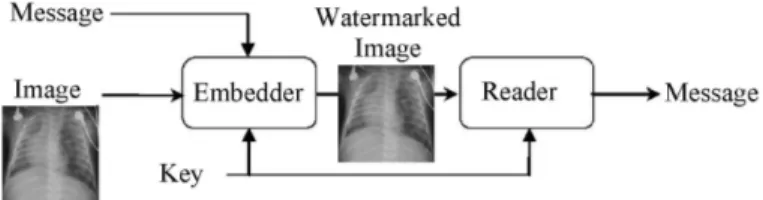
The watermarking of images comes under the more general heading of information hiding: a message is embedded into a document, a host which may be text, sound, video or images. For images, the difference signal between the original image and its watermarked version corresponds to the watermark signal associated with the embedded message. Care must be taken to ensure that the watermarked host document has the same value as the original host document. Figure 10.10 gives an example of a watermarking chain.
Figure 10.10. A watermarking chain
With the link established between the message and its host, we see steganography, watermarking and fingerprinting. Steganography is a form of secret communication where the host, who serves as the hidden communication channel, is of little interest to the message’s recipient. Watermarking and fingerprinting have come to the fore since 1995, to meet the needs of managing DRM (Digital Rights Management). Watermarking involves the insertion of a code identifying the owner, and fingerprinting involves the insertion of a trace linked to the buyer. Since then, other applications have been proposed for information security, such as copy control, restriction of access and integrity control. For more details on watermarking
applications and methods, please refer to digital watermarking [COX 02].
Henceforth, the terms “watermarking” and “data hiding” will be used interchangeably.
For medical imagery, several cases making use of watermarking can be identified [COA 00]:
– the authenticity of images with the insertion of data confirming the origin and the fact that a certain image refers to a particular patient;
– controlling the integrity of images, by putting control information, such as a digital signature, within the image (section 10.3);
– the addition of meta-data (data hiding), allowing the content of images to be enriched by attaching a semantic description of the content [COA 05].
Another, more detailed, scenario combines authenticity with the integrity control of the images, and aims to establish a solid link between these images and the
corresponding test results [COA 06]. In information protection [COA 03],
watermarking is complementary to the mechanisms discussed above, as it merges the protection information and the image to be protected into one entity: a watermarked image.
10.5.2. Watermarking techniques and medical imagery
10.5.2.1. Characteristics
The data-hiding techniques proposed for use with images are numerous and vary in their approach. They do nevertheless have some common characteristics which, depending on the application, should be kept in mind when choosing the appropriate technique:
- robustness: a method is classed as robust if after modification of the watermarked image (a “washing” attack or simple image processing) the hidden information can still be accessed and understood. This property is essential for identifying images which undergo treatment or lossy compression;
- capacity: this measurement expresses the embedding rate as the number of bits buried per pixel of the image (bpp, for “bit per pixel”) and therefore gives an indication of the message size which can be embedded in an image. Data-hiding techniques aim to optimize this parameter and then add useful information to the images;
- security: in some cases access to the watermark and its contents must be restricted; as for cryptography, there are symmetric and asymmetric watermarking methods;
- complexity: this is an indication of the calculation time needed for embedding and extraction; the complexity plays an important role when treating large image volumes;
- invisibility: this is important for medical images, since a watermark must not interfere with the interpretation of an image, in order to avoid affecting the diagnosis. With this in mind, certain watermarking methods have been proposed specifically for medical imagery;
– the need for the original image for decoding is also one of these characteristics; we say that a method is “blind” if the original image is not required in order to extract the watermark; integrity control applications are not possible with non-blind watermarking methods, the question of knowing whether the original image has been modified has no meaning in such cases.
One method can meet certain applications independently, but not simultaneously. A compromise must be reached between capacity, robustness and invisibility. A stronger watermark will better resist alterations to the signal introduced by the compression, or hacking attempts; but its presence will be more obvious to the user and its capacity will be reduced.
10.5.2.2. The methods
In their principles, watermarking methods proposed for medical imagery are only very slightly different from other methods which we can refer to as “classic” methods. They make use of particular adaptation strategies specifically for medical imagery.
In the habitual schemes, two types of algorithm can generally be identified. The first involves additive methods. Starting from a message (a sequence of bits), they generate a signal which is added to the image or a transformation of the image
(DCT, DWT, etc). A technique involving spread spectrum links each bit bj of the
message with the value dj = 1-2bj thus multiplies this quantity by a pseudo-random
sequence Wj low in energy which is then added to the image I to produce the
watermarked image: Iw = I + αdjWj. α is a parameter of insertion or incrustation
strength (robustness parameter). The embedding of a message of N bits adds to the
image the watermark
∑
= = N
j djWj
W
1α . The presence of this watermark is checked by
correlation techniques, which implies the orthogonal nature of the pseudo-random
sequences Wj. The sign of each correlation product gives the value of the embedded
bit. The embedding of a large message can lead to a partially visible watermark W. In order to ensure the invisibility of the watermark, psychovisual criteria are used to adapt the insertion strength to the image locally.
The second group covers substitution methods which, in order to embed a bit of the message, replace a piece of information from the image (its grey levels or a transformation thereof) with a symbol from a dictionary. Detection therefore takes place with a simple re-reading. The method of Least Significant Bit (LSB) substitution is the simplest. This method simply replaces the LSB of an image’s grey
levels with those of the message to be watermarked. For a grey level pixel p(n,m), this means associating the binary value 1 with the odd values of p(n,m), and the value 0 with the even values. This method is far from robust (it is therefore fragile) but does offer a capacity of 1 bpp. More elaborate versions of this approach have since appeared, following the Costa schema [COS 03]. These methods known as informed [COX 02] are based upon structured dictionaries which contain the values that the blocks of pixels will take to carry information.
For medical imagery, three strategies have been established with the key aim of preserving the image interpretation. These are the methods above, methods involving region of non interest watermarking and reversible watermarking methods.
The first methods produce watermarks which replace part of the information in an image. Using them requires careful attention to ensure that the watermark does not interfere with the diagnostic information. The first solutions proposed were techniques secretly modifying the LSB of certain pixels or coefficients of the transform of an image. These are methods with a large capacity, introducing only a slight damage to the original signal but very fragile nevertheless. More recently, robust techniques have been tested with, during the experiments, the involvement of a practitioner giving a threshold of insertion force which should not be crossed [PIV 05]. More generally speaking, the problem with the automatic evaluation of the maximum authorized distortion level is a pertinent question. This problem is far from helped by the wide diversity of signals in the healthcare sector (see Chapter 3) and the availability for practitioners of tools which allow, for example, the isolation of a certain part of the dynamic of an image. These ranges of grey levels vary according to the user, and some may find that the watermark is visible.
One strategy, suggested to optimize the performance of the above methods in terms of robustness and capacity without further damage to the image, is based on the existence in the image of regions with little or no interest for in the image interpretation. These techniques, known as region of non interest watermarking, more often than not place the watermark in the black background of the image [COA 01]. Robustness can be achieved, with the watermark not masking any important information, although a strong watermark can be a hindrance for the physician during his image analysis. The embedding strength must be regulated.
The final approach concerns reversible watermarking methods. The idea is to be able to remove the watermark from the image, thereby restoring the exact same grey levels as in the original image. These techniques make it possible to update the contents of a watermark. This is not the case for the previous methods, where one watermark would have to be added to another. The drawback is that the watermarked image is no longer protected once the watermark has been removed.
Such techniques have benefited from progress in recent years; [COA 05], [COA 06], [CAV 04], [COL 07]. The techniques developed have variable performances depending on the host type to be watermarked and with performances lower than any non-reversible methods. Otherwise, these techniques are very rarely robust, and the desire to maximize the capacity often leads to highly visible watermarks: the watermark must be removed before the image can be used.
Watermarking medical imagery is in its early stages at the moment, with the key difficulty encountered being the level of distortion which it introduces. We can however remain hopeful that the work carried out on improving the quality of image compression (Chapter 5) will lead to solutions allowing the full benefits of watermarking to be appreciated.
10.5.3. Confidentiality and integrity of medical images by data encryption and
data hiding
The applications of watermarking medical imaging are numerous. In this section, we aim to illustrate the combination of cryptography and watermarking in secure image exchange. We saw in section 10.3 that the encryption process could be either symmetric or asymmetric, by block or by stream. Whereas asymmetric algorithms are not appropriate for image encryption due to their calculation time, block algorithms present security problems (due to homogenous zones) and problems with the data integrity. Figures 10.11 demonstrate this problem. The AES block algorithm [AES 01] with a 128-bit key has been applied to the original image (Figure 10.11a) in order to obtain the encrypted image (Figure 10.11b). If the encrypted image is modified during the transfer, it is not necessarily possible to detect this alteration. For example, in Figure 10.11c a small region of the encrypted image has been copied and pasted onto another zone of the image. After decryption, it is possible to view the images, but their integrity cannot be guaranteed as shown in Figure 10.11d.
a) b) c) d)
Figure 10.11. a) Original Lena image, b) image encrypted by AES by 128-bit block, c) copy of a region of the encrypted image, pasted onto another zone, d) decryption of (c)
In order to solve the integrity problem, it is possible to combine a stream cipher algorithm with a secret key for the image and an asymmetric algorithm to encrypt the secret key. A substitutive watermarking method (section 10.5) then allows for the embedding of the encrypted key into the encrypted image [PUE 04], [PUE 07]. If person A sends an image over a network to person B, sender A will use a stream cipher algorithm with the secret key K to encrypt the image. To send key K, A can encrypt it using an algorithm with a public key such as RSA. Let pub(e,n) be the
public key and priv(d,n) the private key for RSA with e = d-1mod(n), so A has his
public and private keys puba(ea,na) and priva(da,na), and B has his public and private
keys pubb(eb,nb) and privb(db,nb). As a result, A generates a secret key K for this
session and encrypts the image with the stream cipher algorithm. Next, A ciphers the
key with the RSA algorithm using his private key priva in order to achieve a key K’:
) mod(
' Kd na
K = a
[10.10]
This key K’ is encrypted a second time with RSA using the public key pubb of
the recipient B to generate K’’: ) mod( ' " Ke nb K = b [10.11] The size of the message to be embedded into the image depends upon the size of
the recipient’s public key and is known to sender A and recipient B. We can therefore calculate the embedding factor and calculate the number of blocks required for the embedding. This key K’’ is embedded into the ciphered image. Finally, A sends the image to B as shown in Figure 10.12. This procedure of K encryption with
priva and pubb ensures the authenticity, and only B can decrypt the image. The
embedding of the key into the image makes the method autonomous and guarantees its integrity. If, during transfer, the image is attacked, then it is no longer possible to extract the right key on reception, and so the image cannot be decrypted.
Figure 10.12. Combination of secret key encryption, public key encryption and a watermarking method
Person B receives the encrypted and watermarked image, and can then extract the encrypted key K’’. He can then identify the sender, A, and decrypt the key K’’ using the private key privb and the public key puba belonging to A:
) mod( )) mod( " (K d nb e na K = b a [10.12] With the acquired key K, B can decipher the image and thus view it. Starting
from the original ultrasound image (512x512 pixels), Figure 10.13a, we have applied a stream cipher algorithm with a key K of 128 bits, in order to obtain the encrypted image Figure 10.13b. If this image is decrypted, we can note that there is no difference between it and the original image. The 128-bit key K was encrypted twice with the RSA algorithm in order to obtain K’’. Due to the length of B’s public key, the length of K’’ is in the region of 1,024 bits. Next, using a watermarking technique in the spatial domain based on the LSB substitution, key K’’ is embedded into the encrypted image (Figure 10.13c). The embedding capacity is of 1 bit for every 256 pixels. The difference between the watermarked, encrypted image and the original is shown in Figure 10.13d. The pixels used for the embedding are visible, the PSNR=75.14 dB. After the decryption of the watermarked, encrypted image, in Figure 10.13c, we reach the final image shown in Figure 10.13e. The difference between the original image and the final one is shown in Figure 10.13f. This figure shows that the differences between the two images (PSNR = 55.28 dB) are spread throughout the image. Nevertheless, because the average value of the α(i) coefficients is equal to zero, the error due to the watermarking is not increased during the decryption stage.
a) b) c)
d) e) f)
Figure 10.13. a) Original image, b) encrypted image with a stream cipher algorithm with 128-bit key, c) image (b) watermarked with the secret encrypted key,
d) the difference between images (b) and (c), e) decryption of image (c), f) the difference between original image (a) and (e)
In order to compare the results of this hybrid method, the watermarking method was applied to the encrypted medical image using the AES algorithm with the ECB and OFB modes (stream cipher mode). After decryption, the image watermarked and encrypted by AES in ECB mode shows a great deal of variation compared to the original image (PSNR=14.81 dB). After decryption, the image watermarked and encrypted by AES in OFB mode presents variations which were not diffused by this mode. The final image quality is good (PSNR=52.81 dB) but an overflow problem remains with the OFB AES mode. The black pixels become white, and vice versa. In conclusion, the combination of encryption and watermarking allows for an autonomous transmission system, and guarantees the integrity of the data transmission.
10.6. Conclusion
In this chapter, we have shown that there are many solutions for ensuring security when sending and storing medical images. In current practice, those solutions offered to secure medical data are based on very traditional protection techniques. These old approaches require either the introduction of certain specific mechanisms, or a longer execution time. These traditional approaches are not suitable for real-time applications or for access from a doctor’s surgery. Some of the solutions proposed in this chapter can be integrated into systems for sending medical images, if they can be proven robust. The main advantage of all these hybrid
approaches is the ability to link several types of coding in one algorithm. In years to come, the appearance of standards in the encryption and watermarking of images will be of great benefit to the safe transmission of medical data.
10.7. Bibliography
[AES 01] AES, Announcing the Advanced Encryption Standard, Federal Information Processing Standards Publication, 2001.
[ALL 94] ALLAËERT F.A, DUSSERRE L., “Security of health system in France. What we do
will no longer be different from what we tell”, International Journal of BioMedical
Computing, vol. 1, p. 201-204, 1994.
[CAV 04] CAVARO-MÉNARD C.,AMIARD S.,“Reversible data embedding for integrity control and authentication of medical images”, in ISIVC’04, Proceedings of 2nd International
Symposium on Image/Video Communications, Brest, July 2004.
[COA 00] COATRIEUX G.,MAÎTRE H.,SANKUR B.,ROLLAND Y.,COLLOREC. R. “Relevance of
Watermarking in medical imaging”, in ITAB'00, Proceedings of ITAB, Washington, USA, November 2000.
[COA 01] COATRIEUX G.,SANKUR B., MAÎTRE H., “Strict integrity control of biomedical
images”, in SPIE, Proc. Electronic Imaging, Security and Watermarking of Multimedia
Contents, p. 229-240, San Jose, USA, November 2001.
[COA 03] COATRIEUX G.,H.MAÎTRE, “Images médicales, sécurité et tatouage”, Annales des
Télécommunications, Numéro Spécial Santé, vol. 58, p. 782-800, 2003.
[COA 05] COATRIEUX G., LAMARD M., DACCACHE, PUENTES W.J., ROUX. C., “A low distortion and reversible watermark: Application to angiographic images of the retina”, in
EMBC'05, Proceedings of Int. Conf. of the IEEE-EMBS, p. 2224-2227, Shanghai, China,
November 2005.
[COA 06] COATRIEUX G.,PUENTES J.,LECORNU L.,CHEZE LE REST C.,ROUX. C., “Compliant secured specialized electronic patient record platform”, In D2H2'00, Proceedings of
D2H2, Washington, USA, November 2006.
[COL 07] COLTUC D., “Improved Capacity Reversible Watermarking”, IEEE International
Conference on Image Processing, ICIP’2007, San Antonio, Texas, USA, September 2007
[COS 03] COSTA M.H.M., “Writing on dirty paper”, IEEE Trans. on Information Theory, vol.
58, p. 782-800, 2003.
[COX 02] COX I.J., MILLER M.L.,BLOOM J.A.., Digital Watermarking, Morgan Kauffman Publishers, San Francisco, CA, 2002.
[DAE 02] DAEMEN J.,RIJMEN.V.,AES, Proposal: The Rijndael Block Cipher, Technical report, Proton World Int.l, Katholieke Universiteit Leuven, ESAT-COSIC, Belgium, 2002.
[DIF 76] DIFFIE W.,HELLMAN M.E., “New directions in cryptography”, IEEE Transactions
[DRO 02] VAN DROOGENBROECK M.,BENEDETT R.,“Techniques for a selective encryption of uncompressed and compressed images”, in Proceedings of Advanced Concepts for
Intelligent Vision Systems (ACIVS) 2002, Ghent, Belgium, September 2002.
[DUC 96] DUCROT H., “Le dosssier médical informatisé face à la Loi Française”,
Informatique et Santé : Aspects Déontologiques, Juridiques et de Santé Publique, vol. 8,
p. 87-96, 1996.
[DUS 97] DUSSERE L., Recommandations déontologiques pour le choix de logiciels destinés
aux cabinets médicaux. Ordre national des médecins, Conseil National de l'Ordre, Ethique et Déontologie, 1997.
[FIS 04] FISCH M.M.,STGNER H.,UHL A., “Layered encryption techniques for DCT-coded visual data”, in European Signal Processing Conference (EUSIPCO) 2004, Vienna, Austria, September 2004.
[GUI 02] GUILLEM-LESSARD S., http://www.uqtr.ca/~delisle/Crypto, visited in 2002.
[KER 83] KERCKHOFFS A., “La cryptographie militaire”, Journal des sciences militaires, vol. 9, p. 5-38, 1883.
[MAN 01] MANICCAM S.S.,BOURBAKIS N.G., “Lossless image compression and encryption using SCAN”, Pattern Recognition, vol. 34, p. 1229-1245, 2001.
[MAN 04] MANICCAM S.S.,BOURBAKIS N.G., “Lossless compression and information hiding
in images”, Pattern Recognition, vol. 37, p. 475-486, 2004.
[NOR 03] NORCEN R.,PODESSER M.,POMMER A., SCHMIDT H.P., UHL A., “Confidential
storage and transmission of medical image data”, Computers in Biology and Medicine, vol. 33, p. 277-292, 2003.
[PIV 05] PIVA A., BARNI M.,BARTOLINI F., DE ROSA A., “Data Hiding Technologies for Digital Radiography”, IEEE Vision, Image and Signal Processing, vol. 152, no. 5, p. 604-610, 2005.
[PUE 01a] PUECH W.,DUMAS M.,BORIE J.C.,PUECH M., “Tatouage d'images cryptées pour
l'aide au Télédiagnostic”, in Proc. 18th. Colloque Traitement du Signal et des Images,
GRETSI'01, Toulouse, France, September 2001.
[PUE 01b] PUECH W.,PUECH M.,DUMAS M., “Accés sécurisé distance d'images médicales haute résolution”, in Proc. 11th. Forum des Jeunes Chercheurs en Génie Biologique et
Médical, Compiègne, France, p. 72-73, June 2001.
[PUE 04] PUECH W.,RODRIGUES J.M., “A new crypto-watermarking method for medical
images safe transfer”, in EUSIPCO'04, Vienna, Austria, 2004.
[PUE 05] PUECH W.,.RODRIGUES J.M., “Crypto-Compression of medical images by selective encryption of DCT”, in EUSIPCO'05, Antalya, Turkey, September 2005.
[PUE 06] PUECH W.,RODRIGUES J.M.,DEVELAY-MORICE J.E., “Transfert sécurisé d'images médicales par codage conjoint : cryptage sélectif par AES en mode par flot et compression JPEG”, Traitement du signal (TS), numéro spécial Traitement du signal
[PUE 07] PUECH W.,RODRIGUES J.M., “Method for Secure Transmission of Data”, Licence WO 2007/045746, April 2007.
[ROD 06] RODRIGUES J.M.,PUECH W.,BORS A.G., “A selective encryption for heterogenous
color JPEG images based on VLC and AES stream cipher”, in CGIV'06, Leeds, UK, 2006.
[SAI 05] SAID A., “Measuring the strength of partial encryption scheme”, in ICIP 2005, IEEE
International Conference in Image Processing, Genova, Italy, vol. 2, p. 1126-1129, 2005.
[SHA 78] SHAMIR A.,RIVEST R.L.,ADLEMAN L., “A method for obtaining digital signatures and public-key cryptosystems”, Communications of the ACM, vol. 21, no. 2, p. 120-126, 1978.
[SCH 97] SCHNEIER B., “Applied cryptography”. Wiley, New York, USA, 1995.
[STI 96] STINSON D., Cryptographie – Théorie et pratique, Thompson Publishing, 1996. [TAN 96] TANG L., “Methods for encrypting and decrypting MPEG video data efficiently”, in