Robot control based on human motion analysis with
IMU measurements
Robin Pellois, Laura Joris and Olivier Br¨
uls
Multibody and Mechatronic Systems LaboratoryUniversity of Li`ege Li`ege, Belgium
Email: {robin.pellois, ljoris, o.bruls}@ulg.ac.be
Abstract—The measurement of the operator motions can lead to innovation in the field of human-robot collaboration. Motion capture data can be used for robot programming by demon-stration as well as controlling and adapting robot trajectories. To measure motion, IMUs represent an interesting alternative compared to other sensing technologies such as vision. In order to illustrate this strategy, a demonstrator has been created to command a robot by human motion. Two IMU sensor modules are set on the human arm and forearm. The orientation of the module with respect to the inertial frame is computed by the fusion of accelerometer, magnetometer and gyroscope data. This information coupled with a simple human arm kinematic model is used to compute the wrist trajectory. The accuracy of this measurement has to be quantified. For that purpose, the estimated trajectory based on the IMU measurement is compared to the trajectory measured using a reference 3D optoelectronic motion analysis system (Codamotion, Charnwood Dynamics Ltd) available in the Laboratory of Human Motion Analysis of the University of Li`ege.
I. INTRODUCTION
Human-robot cooperation is an emerging paradigm which aims at combining the complementary skills of a human operator and an industrial robot in order to achieve complex tasks. The human operator has superior ability to analyse a situation, make a decision, plan the action and coordinate the motion in complex and unstructured environments. On the other hand, an industrial robot can be extremely performant in terms of motion accuracy, reproductibility, reactivity and load carrying capacity. Improvements in this field yield to many new situations. Human and robot can now share the same work space, the robot can see the human, the human can manipulate the robot and other kind of interaction are possible. This new field of robotic also bring new programming methods. In their survey [1], Biggs and MacDonald put forward manual programming against automatic programming. The first one, already implemented on commercalized robots, involves direct modifications of the robot program by the human. The second one, still at the developpment step, consists of using infor-mation from the operator and/or the environnement in order to make the robot modify his program by itself. In that way programming robot becomes easier, faster, more intuitive and no technical skills are necessary.
Inside the category of the automated robot programming, one of the most common field is Programming by Demonstration (PbD). The source of inspiration of this field takes place in the
human-human interaction. When someone explains something to someone else, it could use different ways of communication, by verbal explanations, by showing, by touching, by using appropriate voice intonation... The same ways of communica-tion can be found in the PbD field. The ”touching” interaccommunica-tion already exists, the robot is moved by the operator, motions or positions are recorded and reproduced. An example is the robot Sawyer (Rethink Robotics) wich can be handled by the human, positions are recorded, making programming very intuitive. The robot Pepper (Aldebaran) also master the game ”bal-in-the-cup” after a machine learning process initiated by a demonstration where the human guided the robot hand. The human can speak to the robot either to give instructions or to correct a movement where the robot tries to interprete cues in the human speech. Some research has been done in this field as the work of Lauria et al. [2]. They manage to control a mobile robot by natural speech. It is also possible to ”show” to the robot what to do. The robot acquires data from the human who is executing the task. After a processing step, the robot is able to reproduce the task.
In the problem of showing to the robot, the first question to ask is how to acquire information about human motion. Several technical solutions has been developped. It is possible to distinguish 3 types of solutions based on the acquisition system. One solution category includes all systems based on exoskeletons. Those devices measure directly the joint angle on human limbs. The work of Ijspeert et al. [3] can be mentionned as an exemple. A lot of work is also based on data gloves which measure the motion of the fingers. A second and common technical solution uses optoelectronic devices composed of one or several cameras, lasers, active or passive markers and/or infrared devices. Finally, a third option can be considered : Inertial Measure Unit (IMU). This technology takes already place in the robotic field as in the work of Prayudi et al. [4] or Liu et al. [5] to analyse the human motion in order to improve robot behaviour. Those sensors have some advantages compared to the others systems. They are wireless, easy to use and do not require any special environnement like the opto-electronic systems. They also are lighter, less invasive, smaller than exoskeletons. This work tries to demonstrate that IMUs can be used to measure the human motion in order to command and control an industrial robot arm.
Fig. 1. Diagram of the demonstrator
In a first time the setup and each component are presented. Secondly this article presents the method used to measure the human motion explaining how data are exploited. Finally results are given and first considerations about the accuracy are discussed.
II. THE SET UP
The objective for the robot is to follow in real time the motion of the wrist of the operator. In order to simplify the problem for the first step, the orientation of the wrist is not taken in account and the shoulder of the operator is assumed to be fixed. Thus, the end-effector should follow the relative motion of the operator’s wrist with respect to his shoulder. The setup is composed of 3 different parts : the sensors, the acquisition and processing system and the robot, organized as shown in the figure 1. The trajectory of the human wrist is computed with 2 sensor modules.
A. The sensors
The sensor module used in this work has been developped by the Microsys (Laurent et al. [6]) lab in the University of Li`ege. These 47x25x5 mm PCB are composed of an accelerometer and a gyroscope in the same component and a magnetometer in another component (fig. 2). The wireless module, powered by a 3 volt battery, sends informations by radio frenquency every 0.1 second. The sensors provide the following data defined in a reference frame attached to the sensor module (fig. 2):
The accelerometer measures the linear acceleration ~a and the gravity field ~g. −−−−−−→ Accelero = ax+ gx ay+ gy az+ gz
The magnetometer measures the magnetic field composed of
the Earth magnetic field ~B pointing toward the north pole and some disturbances due to the environnement ~n.
−−−−−−→ M agneto = Bx+ dx By+ dy Bz+ dz
The gyroscope measures the rotational speed of the module.
−−−→ Gyro = ~ω = ωx ωy ωz
B. The Acquisition and Processing System
This system receives data from sensors, processes them and finally sends the displacement command to the robot. These functions are managed by a Raspberry Pi 3 which has the advantages of being easy to programme in C language and well documented. A radio antenna has been added to receive information from sensors. The Raspberry Pi 3 communicates with the robot by ethernet wire via socket connection. To com-mand the robot, the Raspberry Pi sends just the displacement between two time steps.
C. The Robot
The robot applies this exact displacement relatively to an initial position. To get a smooth motion the speed of the robot has to be adapted accordingly to the length of the displacement. The robot used for the demonstrator is an ABB IRB120 with a reach of 580 mm and handle a payload of 3 kg. The Robot is programmed in RAPID language.
III. THEMOTIONESTIMATION
The first idea was to set one module on the wrist of the operator and estimate the position from a well known start position. But this idea involves a double integration of the accelerometer signal which would introduce an increasing error of the position over the time. In order to avoid this issue, several modules are used.
A. The References Frames
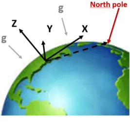
Two references frames are necessary and need to be defined. Firstly, the inertial frame, noted E is based on Earth features as shown in the figure 2. The z-axis is oriented along the gravity vector and pointing upward. The x-axis is perpendicular to ~g and oriented towards the north pole. Then the third axis can be deduced from the two others axis.
Secondly a local frame attached to the sensor module is defined according to the figure 3. During the human motion, this frame is constantly moving with respect to the inertial frame. At the step time n, the local frame will be noted Sn i,
Fig. 2. The inertial frame
Fig. 3. The sensor module and the local frame
B. The Human Arm model
To be able to compute the human wrist trajectory, a model of the human arm is necessary. The chosen model is simply composed of 2 segments for the arm and forearm and 2 spherical joints for the elbow and the shoulder as shown on figure 4. The length of each segment has been measured directly on the operator. The objective is to compute the wrist trajectory with respect to the inertial frame centered in the shoulder since it is considered fixed. According to the human
Fig. 4. The human arm model
arm model the wrist trajectory is equivalent to−→AC(t)E which
can be expressed as follows : −→ AC(t)E = −−→ AB(t)E+ −−→ BC(t)E −→ AC(t)E = RESn 1× −−→ AB(t)Sn 1+ R E Sn 2× −−→ BC(t)Sn 2
with RESn1 the rotationnal matrix allowing the changement between the local frame Sn 1 attached to the module 1 and the inertial frame E . RE
Sn2 is the same rotational matrix related
to the second module.
Furthermore the expression of −AB(t)−→ Sn 1 and
−−→
BC(t)Sn 2 only
depends on how the modules are set on each segment of the human arm. By consequence, the problem boils down to estimate the rotationnal matrix RE
Sn for each sensor.
C. The Rotationnal Matrix
Two methods are now presented to compute the rotational matrix RE
Sn, one using the accelerometer and
the magnetometer data and another one using gyroscope data. 1) Accelerometer and magnetometer data based method: This method is only applicable in phases during which the linear acceleration of the arm is negligible compared to the gravity. Under this condition the gravity vector is known in both inertial and local frames which leads to a first set of 3 equations used to calculate a part of the rotational matrix.
The same idea can be applied to the magnetometer. The vector −M ag is the measure from the magnetometer express−−→ with respect to the local frame Sn and is equivalent to the
x-axis in the inertial frame. This lead to 3 more independent equations.
Finally, using the orthogonality property of a rotational matrix, 3 other independent equations can be extracted. The complete matrix RSEn can then be evaluated by solving a system of 9 equations.
2) Gyroscope data based method: The data from the gyroscope ~ωnSn represent the rotational speed at the moment n. By integration on the duration of the time step, the orientation of the frame Sn at the moment n with respect to
the frame Sn−1 is known. Applying this equation at every
time step enables to compute the rotational matrix RSn 2
Sn 1 for
any moment n1and n2. Finally, using the first method based
on accelerometer and magnetometer data to initialised the process enables to compute any RE
Sn.
3) Combination of both methods: Both methods have ad-vantages and drawbacks. The first one is sensitive to noise from the magnetometer and has to be rejected if the sensor undergos a too high linear acceleration. But this method enables to compute independently the rotational matrix from any Sn frame at any time step n to the inertial frame E.
On the other side, the method based on gyroscope data has the advantage of not being sensitive to the environnemental disturbances and is not limited by the motion of the arm itself. But the signal is integrated during the process which involve a
Fig. 5. Experimental setup
drift over time. This phenomenon makes this method useless for the long time intervals.
A solution is to mix both methods to compute a rotational matrix. A complementarity filter [7] has been implemented into the algorithm. This filter mixes the results of both methods at a certain percentage. However, the filter is not applied directly on the rotational matrix but on the vector representing the angle-axis coordinates of the rotational matrix.
IV. RESULTS
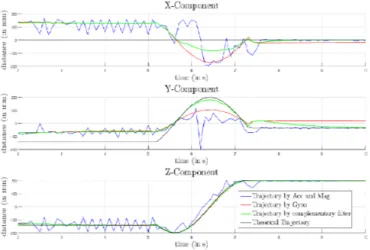
This filter bring a significant improvement to the trajectory. As an illustration of this improvement, the trajectory computed by the filter has been compared to the trajectory from the gyro-scope data and from the accelerometer and the magnetometer data. One sensor module has been set on a 200 mm aluminium bar attached to a servomotor wich impose a circular trajectory from 135 deg to -100 deg in the yz-plane with respect to the inertial frame. A compass has been used for the orientation of the setup. The figure 5 describes the experimental setup. A static period before and after the circular motion has been observed. The figure 4 shows the results of each component of the trajectory. The black curve is the reference trajectory. First the x-component should be zero since the movement is in the yz-plane. This is due to disturbances in the magnetic field. Some considerations about this issue follow later in this article. Obviously the trajectory estimated by the first method (blue curve) is useless during the motion part. This chaotic trajectory is amplified by the vibration of the aluminium bar used for the setup. However, during the second motionless parts, the results are pretty accurate. On the other side, the red line, based on the gyscope data, give a curve following the theorical trajectory. But a shift appear quickly and is never caught up. The trajectory from the filter better fits the reference trajectory during the motion part. It also catches up the gap with the theorical trajectory in the motionless part. A significant example is the motionless part after the movement of the y-component where the filtered trajectory progressively follows the trajectory computed by the accelerometer and magnetometer data which fit with the reference trajectory.
At this point the robot is able to follow the wrist trajectory in real time. But a large imprecision is visible and attributed to the magnetometer noise. This high sensitivity of the
magne-Fig. 6. Components of a circular trajectory measure by 3 differents methods.
tometer to magnetic disturbances was confirmed by additional dedicated experiments.
V. CONCLUSION
The IMU is an interesting technology to measure human motion in order to programme, command, control and col-laborate with a robot. The method presented here uses two sensor modules, one for each segment of the human arm, in order to estimate the wrist trajectory. Each module is used to calculate the rotational matrix representing the transformation from the local frame to the inertial frame. Two methods are used to calculate this matrix, one based on accelerometer and magnetometer data and the other one based on gyroscope data. Both methods have advantages and drawbacks. The first one is accurate in really slow movements and is very sensitive to magnetic disturbances, the other one give a smooth trajectory but drift over time. A complementary filter is used to take avantage of both methods. The estimated trajectory of the wrist is then used to move a robot arm. An important trajectory default has been observed between the human wrist trajectory and the movement of the robot. It has been experimented that the magnetometer, easily disturbed by the environnement, is the main source of error in comparison to the accelerometer. The future work will focus on how to improve the measure-ment of the wrist trajectory by a better magnetometer signal or by another method not based on the magnetometer. In a second time, the next steps will be to integrate the position and the orientation of the wrist and then the hand.
ACKNOWLEDGMENT
This work was supported by the Interreg V programme of the Greater Region within the Robotix Academy project.
REFERENCES
[1] G. Biggs and B. MacDonald, “A survey of robot programming systems.” [2] E. K. Stanislao Lauria, Guido Bugman Theocharis Kyriacou, “Mobile
robot programming using natural language.”
[3] S. S. Auke Jan Ijspeert, Jun Nakanishi, “Movement imitation with nonlinear dynamical systems in humanoid robots.”
[4] D. K. Iman Prayudi, Eun-Ho Seo, “Implementation of an inertial measure-ment unit based motion capture system,” Ubiquitous Robots and Ambient Intelligence (URAI), 2011 8th International Conference on.
[5] K. S. T. Liu, H. Utsunomiya Y. Inoue, “Synchronous imitation control for biped robot based on wearable human motion analysis system.” [6] F. A. P. Laurent, F. Dupont S. Stoukatch, “Ultra-low power integrated
microsystems.”