O
pen
A
rchive
T
OULOUSE
A
rchive
O
uverte (
OATAO
)
OATAO is an open access repository that collects the work of Toulouse researchers and
makes it freely available over the web where possible.
This is an author-deposited version published in :
http://oatao.univ-toulouse.fr/
Eprints ID : 12637
The contribution was presented at RTAS 2013 :
http://www.cister.isep.ipp.pt/rtas2013/wip
To cite this version :
Ermont, Jérôme and Fraboul, Christian Computing the exact
worst-case End-to-end delays in a Spacewire network using Timed Automata. (2013)
In: 19th IEEE Real-Time and Embedded Technology and Applications Symposium
(RTAS 2013), 9 April 2013 - 11 April 2013 (Philadelphie, PA, United States).
Any correspondance concerning this service should be sent to the repository
administrator:
[email protected]
Computing the exact worst-case End-to-end delays
in a Spacewire network using Timed Automata
J´erˆome Ermont, Christian Fraboul
Universit´e de Toulouse - IRIT - INPT/ENSEEIHT {jerome.ermont, christian.fraboul}@enseeiht.fr
Abstract—Spacewire is a real-time communication network for use onboard satellites. It has been designed to transmit both payload and control/command data. To guarantee that communications respect the real-time constraints, designers use tools to compute the worst-case end-to-end delays. Among these tools, recursive flow analysis and Network Calculus approaches have been studied. This paper proposes to use the model-checking approach based on timed automata to compute the exact worst-case end-to-end delays and two worst-case studies are presented.
I. INTRODUCTION
SpaceWire [1] is a communication network for use onboard satellites which has been developed by the European Space Agency and the University of Dundee. It provides high-speed data exchanges, from 2Mbps to 200Mbps, between sensors, memories, processing units and downlink telemetry.
One goal of SpaceWire is to carry both the payload and the command/control traffic instead of using dedicated buses, as MIL-STD-1553 buses, for both of them. These two char-acteristics need different requirements: low throughput and very strict time constraints for command/control traffic and a sustained high bandwidth for payload. Using point-to-point SpaceWire links, both characteristics are easily satisfied. But SpaceWire is based on a part of the IEEE-1355 standard [2] and is defined to connect several equipments. So SpaceWire is a packet switching network.
Due to the space requirements (an important one is the radiation tolerance), routers have to store a minimal amount of data. To ensure this ability, SpaceWire uses wormhole routing: packets are not stored completely but can be forwarded as soon as the output port is free. If the output port is not free, the packet is blocked. In that case, the packet cannot be transferred from the upstream router blocking other packets. The consequence is a variation of the end-to-end (ETE) delays for the packets. A method to verify that the time constraints are guaranteed must be defined.
A similar problem arises in the context of avionics where an upper bound has to be computed in respect to the certification. For this, different solutions exist. Two of them are based on Network Calculus ([3], [4]) and Trajectories ([5], [6]). However, the obtained upper bounds are pessimistic due to the assumptions made by these two approaches.
Other works have been devoted to compute the exact ETE delays of an AFDX network. Existing model checking approaches ([4], [7]) implement an exhaustive analysis of all the possible scenarios. However, it cannot be applied to AFDX
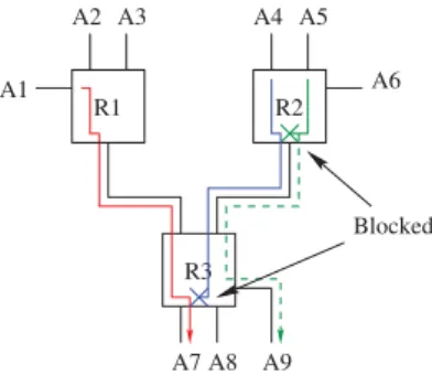
Blocked R1 R2 R3 A1 A2 A3 A4 A6 A7 A8 A9 A5
Fig. 1. Wormhole routing
configurations with more than 10 flows (a real one is more than 1000 flows) because of the well-known combinatorial explosion problem. In [8], the authors extend the study by considering the scheduling of the flows in the network. This drastically reduces the number of considered scenarios.
As said before, in SpaceWire, the command/control mes-sages have to be delivered before their deadlines. In [9], the authors propose to compute an upper bound of the worst case ETE delay of each message. Two methods have been studied: one based on Network Calculus and one based on a recursive flow analysis.
Because the size of a SpaceWire architecture is limited, this paper proposes to compute the exact worst case ETE delays using the timed automata theory.
The wormhole routing mechanism is reviewed in Section II. Then, we give the timed automata model of the SpaceWire network in Section III. Two case studies are described in Section IV.
II. WORMHOLE ROUTING
Memory consumption is an important challenge of space systems because radiation tolerant memories are very expen-sive. Furthermore, classical routing policies, such as store and forward policy, need to buffer data and cannot be used. In a wormhole routing system, packets are not totally stored in buffers but transmitted, item by item, as soon as the output port is free.
To explain the behavior, let us consider the network ar-chitecture in Figure 1. When receiving the first character of a packet sent by the application A1, the router R1 determines the appropriate output port. If the output port is free, the packet is
immediately transmitted to the router R3 and the output port is marked as occupied. The router R3 receives the packet, transmits it to the destination A7 marking the output port as occupied.
Suppose now that the application A4 sends a packet to the application A7 too. The output port of the router R2 is free, the packet is sent to the router R3, marking the output port the router R2 as occupied. The output port of the router R3 is occupied. The packet is then blocked in a small input buffer, 64 bytes in Spacewire, of R3.
And, suppose that the application A5 sends a packet to the application A9. The packet is blocked in the router R2, waiting to the output port occupied by the packet sent by A4.
When the packet from A1 is totally received by A7, the output port of R3 becomes free and the packet from A4 is transmitted to A7. When the output port of R2 becomes free, the packet from A5 will be transmitted.
If two packets are waiting for the same output port, two-level priority queueing is used to reduce the blocking duration of urgent packets. For packets with the same priority level, a simple round-robin procedure is executed to determine which one has to be transmitted as soon as the output port becomes free. This mechanism allows a fair access to the output port but does not guarantee a bounded delay for the transmission of the packets.
In the next section, these characteristics will be modeled in the timed automata theory.
III. MODELING USING TIMED AUTOMATA
This section proposes a review of the timed automata theory. Then, the modeling of the Spacewire architecture is given. Finally, the method used to compute the worst-case ETE delay is explained.
A. Timed automata
Timed automata have been first proposed by Alur and Dill [10] in order to describe systems behavior with time. A timed automaton is a finite automaton with a set of clocks, i.e. real and positive variables increasing uniformly with time. Transitions labels can be a guard, i.e. a condition on clock values, actions, updates, which assign new value to clocks.
The composition of timed automata is obtained by a syn-chronous product. Each action a executed by a first timed automaton corresponds to an action with the same name a executed in parallel by a second timed automaton. In other words, a transition which executes the action a can be fired only if another transition labelled a is possible. The two transitions are performed simultaneously. Thus communication uses the rendez-vous mechanism.
Performing transitions requires no time. Conversely, time elapses in nodes. Each node is labelled by an invariant, that is a boolean condition on clocks. The node occupation is dependent of this invariant: the node is occupied if the invariant is true.
Several extensions of timed automata have been proposed. One of these extensions is timed automata with shared integer
Ask_to_forward Forward_granted At_least_one_message Transmission t<=delay[idRouter_current][idPort]*L[idMes] Packet_blocked No_message idApp : t_idApp ask_transmit[idApp][idPort][idRouter_current]? push(idApp), nbAccess++ ask_transmit[idMes][tableRoute[idMes][idRouter_next]][idRouter_next]! ok_to_transmit[idMes][idPort][idRouter_current]! t=0 ok_to_transmit[idMes][tableRoute[idMes][idRouter_next]][idRouter_next]? nbAccess>=1 idMes=chosen_mess(), t=0 idApp : t_idApp ask_transmit[idApp][idPort][idRouter_current]? push(idApp), nbAccess++ idApp : t_idApp ask_transmit[idApp][idPort][idRouter_current]? push(idApp), nbAccess++
nbAccess>1 && t==delay[idRouter_current][idPort]*L[idMes]
pop(),
nbAccess--nbAccess==1 && t==delay[idRouter_current][idPort]*L[idMes]
t=0,pop(),
nbAccess--idApp : t_nbAccess--idApp
ask_transmit[idApp][idPort][idRouter_current]?
push(idApp), nbAccess++
Fig. 2. Timed automaton of an outport of a router
variables. The principle consists in defining a set of integer variables which are shared by different timed automata. Con-sequently, the values of these variables can be consulted and updated by the different timed automata [11].
A system modeled with timed automata can be verified using a reachability analysis which is performed by model-checking. It consists in encoding each property in terms of the reachability of a given node of one of the automata. So, a property is verified by the reachability of the associated node if and only if this node is reachable from an initial configuration. The approach that is considered in this paper is based on timed automata with shared integer variables which are represented by nodes of a timed automaton. The modeling of a Spacewire architecture with timed automata is now presented. It is based on Uppaal [11].
B. Modeling a Spacewire architecture
A Spacewire architecture is composed of periodic functions and routers. The timed automata system is then composed of:
• one automaton per periodic function, which generates
periodically a packet;
• one automaton per router output port, which models the
transmission of packets on the output link, considering the blocking mechanism, the capacity of the link and the length of the message.
Figure 2 is the timed automata model of an output port. When a packet is received by the output port, it is pushed in an input queue corresponding to its priority level. Then, the modeled behavior is as follow:
1) when the output port is free, a packet is chosen consid-ering the policy as explained in Section II. The output port of the router is then blocked for other packets; 2) the system immediately asks to transmit the packet to
the next router. This simulates the transmission of the head of the packet to the next router;
3) while the signal ok to transmit is not received by the automaton, the packet is blocked. In the next router, three cases are possible:
• the output port is free and the considered packet is
chosen, the router sends the signal ok to transmit and the packet is released;
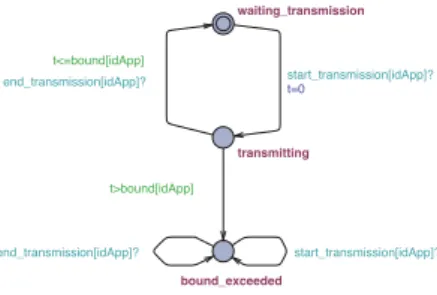
bound_exceeded transmitting waiting_transmission end_transmission[idApp]? start_transmission[idApp]? t>bound[idApp] t<=bound[idApp] end_transmission[idApp]? start_transmission[idApp]?t=0
Fig. 3. Test automaton to compute the ETE transmission delay
• the output port becomes free and another packet is
chosen, the considered packet is still blocked in all the upstream routers.
• the output port is waiting for the signal
ok to transmit from a downstream router. So, the packet is blocked in the router and all its upstream routers.
This behavior is generalized for all the routers and simulates the progress of the packet item by item in the network;
4) finally, when receiving the signal, the path to the destina-tion is free and the packet is transmitted. The automaton waits for a transmission duration corresponding to the length of the packet (L[idMes]) times the capacity of the output link (delay[idRouter][idPort]).
The global model is obtained by combining timed automata modeling periodic functions, which are not presented here, and timed automata representing output ports of the routers.
Finally, the worst-case ETE transmission delays can be computed using the model-checking approach.
C. Computing the worst-case ETE transmission delay
The worst-case ETE delay is obtained by model checking. The method consists in verifying that all the packets are received before a bounded delay. The test automata method is used to help the verification process. It consists in verifying if the rejected node of this automaton is reachable or not.
When sending a packet, applications send immediately a signal start transmission, which indicates the beginning of the transmission. The test automaton of the worst-case ETE transmission delay is depicted in Figure 3. The sig-nal end transmission needs to be received before a delay
bound started when the test automaton receives the signal
start transmission. If not, the rejected node bound exceeded is reached and the property is false.
IV. CASE STUDIES
In this section, we will present two case-studies.
The first architecture shows the impact of crossed flows and slow links while using recursive flow analysis and Network Calculus (NC) in [9]. We can compare the results obtained by these methods with the exact worst-case ETE transmission delays obtained by model-checking.
S12 S34 R D13 D24 L1 L2 L3 L4 f2 f3 f1 f4
Fig. 4. A first SpaceWire architecture Flow Scenario 1 Scenario 2 L4(Mbps) 50 0.2
Size Period Size Period f1 4000 20 4000 20
f2 500 8 20 32
f3 5000 20 5000 20
f4 400 8 20 32
TABLE I
DIFFERENT SCENARIOS OF THE SECOND CASE STUDY
The second architecture is close to a real industrial Spacewire network which can be used in an observation satellite and shows the limitations of the method.
A. A first architecture: comparison of model-checking with recursive flow analysis and Network Calculus
In Figure 4, the network architecture is composed of 4 applications and a router [9]. The bound of the worst-case ETE delays is computed considering the crossed paths and
by varying the capacity of the link L4. Table I shows the
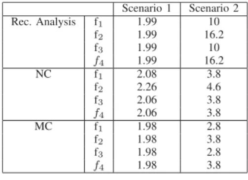
configuration of different studied scenarios and Table II gives the computed ETE delays in ms of the different methods.
In the first scenario, following the remarks in [9], the recursive flow analysis gives the optimal bound but not the
NC. And in the second scenario, the capacity of the link L4
is set to 0.2 Mbps and f2and f4sends small sized packets. In
this situation, NC gives better results than the recursive flow analysis.
For the two scenarios, model-checking gives the exact worst-case ETE transmission delays. They are close to those computed by the recursive analysis in the first scenario. The difference is due to the numeric approximations of the methods. The pessimism of recursive flow analysis and NC can be determined for the second scenario.
The verification of the worst-case ETE delays of each flow
fi takes about 2 minutes on a Macbook with 2.2 GHz Intel
Core i7 processor having 8 GB RAM.
B. A second architecture: an industrial-close architecture
A second case study is given in Figure 5. It is composed of 7 sending applications and 3 routers. This is close to an industrial architecture such as the one shown in [9] (9 application units and a processor module which send data and a memory unit and 2 telemetry units which receive data).
In the system of Figure 5, every application Ai sends a
packet fi to the application AD (destination). The capacity of
the links is constant and equal to 50 Mbps. The configuration and the computed worst-case ETE delays in ms are given in table III.
Scenario 1 Scenario 2 Rec. Analysis f1 1.99 10 f2 1.99 16.2 f3 1.99 10 f4 1.99 16.2 NC f1 2.08 3.8 f2 2.26 4.6 f3 2.06 3.8 f4 2.06 3.8 MC f1 1.98 2.8 f2 1.98 3.8 f3 1.98 2.8 f4 1.98 3.8 TABLE II
RESULTS FOR THE DIFFERENT SCENARIOS
A0 A1 A2 A3 A4 A5 A6 R1 R2 R3 AD f0 f1 f2 f3 f4 f5 f6
Fig. 5. An industrial-close architecture
The main goal of this architecture is to show the impact of the number of transmitting functions in the system.
The evaluation of the worst-case ETE transmission delays takes about 10 min to be computed on a Macbook with 2.2 GHz Intel Core i7 processor having 8 GB RAM. However, by adding only one more application, the evaluation cannot be performed.
For this architecture, flows fi arrive synchronously at the
output port of routers R1 and R2. Model-checking performs
an exhaustive analysis of the arrival orders. The number of scheduled transmissions is then too huge to be computed and leads to the well-known combinatorial explosion problem.
But, the timed automata modeling considered here does not take into account the real scheduling of the packets according to the periods of the functions. By doing this, the number of possible scenarios should be reduced and a bigger architecture could be evaluated. Application A0 A1 A2 A3 A4 A5 A6 Period 20 20 20 20 20 20 20 Flow f0 f1 f2 f3 f4 f5 f6 Length (bytes) 4000 200 5000 200 4000 5000 4000 WC ETE delay 4.44 4.44 4.48 4.48 3.86 4.48 3.86 TABLE III
CONFIGURATION OF AN INDUSTRIAL-CLOSE ARCHITECTURE AND
COMPUTED WORST-CASEETEDELAYS
V. CONCLUSION
The paper proposes a model-checking approach to compute the exact worst-case ETE delays of Spacewire periodic flows. Spacewire standard uses wormhole routing to share commu-nications on the network. This mechanism has been modeled using timed automata theory.
The paper proposes then two first case studies to show the feasibility of the computation of the worst-case ETE delays on a Spacewire architecture.
However, even if a Spacewire network architecture is quite small, the well-known combinatorial problem arises: a system with more than 7 sending applications and 3 routers cannot be analyzed due to:
• the scale of time units: few milliseconds for the periods
of applications and few nanoseconds for the transmission delays;
• the real number of messages in the network: several
packets of a same application can be present in the network due to the period value.
Thus, the number of states considered by the model-checking approach increases with the different possible val-uations of clocks and the different possible packet scheduling. A possible solution to reduce this number could be the one used in [8]. The approach consists in considering only the possible scenarios leading to the worst-case ETE delays. This approach allows to verify AFDX networks with up to 20 flows and should be applied to an industrial Spacewire architecture such as the one presented in [9].
REFERENCES
[1] S. Parkes and P. Armbruster, “SpaceWire: a spacecraft onboard network for real-time communications,” in Real Time Conference, 2005. 14th
IEEE-NPSS, june 2005, pp. 6 –10.
[2] “IEEE Standard for Heterogeneous Interconnect (HIC) (Cost, Low-Latency Scalable Serial Interconnect for Parallel System Construction),”
IEEE Std 1355-1995, p. i, 1996.
[3] J.-Y. Le Boudec and P. Thiran, Network Calculus, ser. Lecture Notes in Computer Science (LNCS). Springer Verlag, 2001.
[4] H. Charara, J.-L. Scharbarg, J. Ermont, and C. Fraboul, “Methods for bounding end-to-end delays on an AFDX network,” Real-Time Systems,
Euromicro Conference on, vol. 0, pp. 193–202, 2006.
[5] S. Martin and P. Minet, “Schedulability analysis of flows scheduled with FIFO: application to the expedited forwarding class,” Parallel and
Distributed Processing Symposium, International, vol. 0, p. 167, 2006.
[6] H. Bauer, J.-L. Scharbarg, and C. Fraboul, “Improving the Worst-Case Delay Analysis of an AFDX Network Using an Optimized Trajectory Approach,” Industrial Informatics, IEEE Transactions on, vol. 6, no. 4, pp. 521 –533, nov. 2010.
[7] M. Lauer, J. Ermont, C. Pagetti, and F. Boniol, “Analyzing End-to-End Functional Delays on an IMA Platform,” in ISoLA, ser. LNCS, vol. 6415. Springer, 2010, pp. 243–257.
[8] M. Adnan, J. Scharbarg, J. Ermont, and C. Fraboul, “An improved timed automata approach for computing exact worst-case delays of AFDX sporadic flows,” in Emerging Technologies and Factory Automation
(ETFA), 2012 IEEE 17th Conference on. IEEE, September 2012.
[9] T. Ferrandiz, F. Frances, and C. Fraboul, “A Sensitivity Analysis of Two Worst-Case Delay Computation Methods for SpaceWire Networks,” in
Real-Time Systems (ECRTS), 2012 24th Euromicro Conference on, july
2012.
[10] R. Alur and D. L. Dill, “A Theory of Timed Automata,” Theoretical
Computer Science, vol. 126, pp. 183–235, 1994.
[11] K. G. Larsen, P. Pettersson, and W. Yi, “UPPAAL in a Nutshell,”
International Journal on Software Tools for Technology Transfer, vol. 1,