To link to this article:
DOI:10.1504/IJMMM.2011.039649
Official URL:
http://dx.doi.org/10.1504/IJMMM.2011.039649
This is an author-deposited version published in:
http://oatao.univ-toulouse.fr/
Eprints ID: 8454
To cite this version:
Wagner, Vincent and Baili, Maher and Dessein, Gilles and Lallement, Daniel
Experimental study of coated carbide tools behaviour: application for
Ti-5-5-5-3 turning. (2011) International Journal of Machining and Machinability of
Materials, Vol.9 (n° 3/4). pp. 233-248. ISSN 1748-5711
O
pen
A
rchive
T
oulouse
A
rchive
O
uverte (
OATAO
)
OATAO is an open access repository that collects the work of Toulouse researchers and
makes it freely available over the web where possible.
Experimental study of coated carbide tools
behaviour: application for Ti-5-5-5-3 turning
V. Wagner*
Ecole Nationale d’Ingénieurs de Tarbes, Laboratoire Génie de Production, 47 Avenue d’Azereix BP 1629, 65016 Tarbes cedex, France Fax: +33(0)5-62-44-27-08 and
Messier Dowty Bidos, Rue Guynemer, BP39, 64401 Oloron Sainte Marie, France
Fax: +33(0)5-59-89-61-51 E-mail: [email protected] *Corresponding author
M. Baili and G. Dessein
Ecole Nationale d’Ingénieurs de Tarbes, Laboratoire Génie de Production, 47 Avenue d’Azereix BP 1629,65016 Tarbes cedex, www.enit.fr, France Fax: +33(0)5-62-44-27-08
E-mail: [email protected] E-mail: [email protected]
D. Lallement
Messier Dowty Bidos, Rue Guynemer, BP39, 64401 Oloron Sainte Marie, France
Fax: +33(0)5-59-89-61-51
E-mail: [email protected]
Abstract: The goal of this paper is to study the relation between the input data
(conditions and geometry of cut) and answers (wear of tool, forces and cutting temperatures) when machining the Ti-5-5-5-3 alloy treated. This study has shown that the cutting process is different and that the slip forces are preponderates. Compared with other materials, the specific cutting pressure is higher and does not vary according to the cutting speed but depend on feed rate. Moreover, both edge preparation and feed rate have an influence on cutting force direction. Besides, cutting temperatures are high and almost similar to those provided by high speed machining with low cutting speed. Finally, we have shown that failure modes are different from those obtained when machining other titanium alloys. Built-up edge is the most deteriorating phenomenon and no flank wear was met in our study context.
Keywords: Ti-5-5-5-3; cutting force; cutting temperature; cutting conditions;
tool geometry; wear.
Reference to this paper should be made as follows: Wagner, V., Baili, M.,
Dessein, G. and Lallement, D. (2011) ‘Experimental study of coated carbide tools behaviour: application for Ti-5-5-5-3 turning’, Int. J. Machining and
Machinability of Materials, Vol. 9, Nos. 3/4, pp.233–248.
Biographical notes: Vincent Wagner is an Associate Professor which is
presently preparing his PhD work at the Laboratory Genus of Production, France. His researches are focused on cutting force model and cutting temperature. He works also on increasing of titanium alloys machinability.
Maher Baili is an Assistant Professor of Mechanical Design and Production in the National Tarbes Engineering School. His research topics are machining of hard-to-cut materials, cutting forces modelling and surface integrity.
Gilles Dessein is an Assistant Professor of Production in the National Tarbes Engineering School. His research topics are high performance machining and CAD-CAM. His current research focuses on stability and dynamics of milling process, solution against thin walled part vibrations, surface integrity and machining of hard-to-cut materials.
Daniel Lallement works as an Engineer in the Department of Manufacturing Engineering at the Bidos Center, Messier Dowty. His actual topic is the analyses of Ti-5-5-5-3 cutting specificities, in order to develop better tools and improve a global process that will ensure optimised productivity gains.
This paper is a revised and expanded version of a paper entitled ‘Étude expérimentale du comportement des carbures revêtus en tournage du Ti 5553, par mesure d’efforts et d’usure d’outil’ presented at JSTMM‘08 (Journée Scientifiques et Techniques en Mécanique et Matériaux), Monastir (Tunisia), 14–15 November 2008.
1 Introduction
The realisation of aeronautic parts with strong mechanical properties requires the use of high performance materials. Indeed, for the manufacture of their landing gears, Boeing proposed to move from one near β titanium alloy: Ti-10V-2Fe-3Al (Ti-10-2-3) to another: Ti-5Al-5Mo-5V-3Cr (Ti-5-5-5-3). This is because of the higher working strengths and wider processing window of Ti-5-5-5-3 (Jones et al., 2008). Currently, the available cutting tools and methods of industrialisation do not permit an interesting productivity and restrain possibilities of realisation of a part where the volume of chip is very important. So, the objective of improving the productivity for this material necessarily passes by understanding phenomena of its machining.
Nowadays, many researchers study machining of such materials (with poor machinability). They have shown that machining these materials leads to an unknown and new cutting process (Ezugwu and Wang, 1997). Saglam et al. (2007) have studied the effect of geometry of cut and the cutting conditions on forces and cutting temperatures. Deshayes (2007) have analysed the evolution of cutting force and wear of inserts with chip breaker. Other authors oriented their efforts toward the influence of the
cutting edge geometry on cutting forces for machining conventional materials as aluminium and steel (Fang and Wang, 2005; Yen et al., 2004). Furthermore, Ranganath et al. (2007) and Karpat and Ozel (2008b) investigated the relationship between honed edge tools and the cutting process. These papers used two different modelling and analysis. In Karpat and Ozel (2008a) and Ren and Altintas (2000), models of cutting forces and cutting temperatures for chamfered edge tools are provided. The first work is based on a finite element model, whereas, the second uses the shear band model.
Knowledge of tool failure modes involved during machining materials with poor machinability is thus needed in order to optimise the process. Some works allow to the understanding of tool failure modes when machining these new materials. Indeed, Ezugwu and Wang (1997) established the prominent failure modes when machining titanium alloys: flank wear, crater wear, chipping and catastrophic failure. These are caused by high cutting temperature, high cutting stresses and the strong chemical reactivity of titanium. Nabhani (2001) explained that higher cutting temperature and quasi-static contact lead to adhesion and welding between the tool and the workpiece material. Corduan et al. (2003) mentioned that machining Ti-6Al-4V generates high cutting temperature producing notch for CBN inserts or crater and flank wear for PCD inserts and a phase changes of the material tools. Wear depends also on tool geometry, Manjunathaiah and Endres (2000) establishes a new model that explicitly includes the effects of edge hone for orthogonal turning machining. Pawade et al. (2007) makes a link between using a honed plus chamfered cutting edge and reducing the cutting forces in the machining of Inconel 718.
The goal of this paper is to understand relations between input data (conditions and geometry of cut) and answers (wear of tool, forces and cutting temperatures) for turning Ti-5-5-5-3 without cutting fluid. This relationship is called the first level. On a second level, we had to understand interactions between phenomena of wear, forces and cutting temperatures. Finally, in the last level, forces, cutting temperatures and wear modify the geometry of cut that have influence on answers of the machining process. In term of cutting forces, we have shown that the machining of the Ti-5-5-5-3 generates cutting forces more important than the classic materials. The optimal choice is to use a tool with small value of honing, a rake angle of 20° and a feed rate superior to the honing value. The cutting speed is between 30 and 50 m/min. In addition to that, if we analyse wear phenomenon, we see that machining the Ti-5-5-5-3 does not generate the same modes of deterioration of tools as classic alloys of titanium (as depicted in Nouari et al., 2008) or Ti-5-5-5-3 not treated (as detailed in Arrazola et al., 2008). Indeed, no wear of clearance surface is obtained as affirmed in Nouari et al. (2008) and Arrazola et al. (2008).
2 Experimental set-up
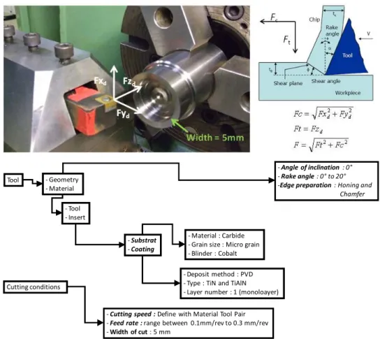
To characterise cutting forces, cutting temperature and wear of tool, a set of experiments was conducted on a CNC lathe without cutting fluid (Figure 1). For the cutting forces tests, a treated Ti-5-5-5-3 thin-walled tube has been used as a work piece. The thickness of the tube is 5 mm. The wear tests have been made in straight turning operation on a 50 mm diameter tube. The mechanical properties of the used material are: density = 4,650 kg/m3; ultimate strength = 1,240 MPa; elongation = 2%; thermal conductivity = 5.3 W/m°C; specific heat = 500 J/Kg°C. All tests have been made with
coated carbide tool. The substrate is a carbide micro size grain. We have used a TiN coating for cutting force tests and a TiAlN coating for wear tests. For all tools, the coating method deposit is PVD. A dynamometer platform has been used for the cutting forces measurements (Kistler 9263-A). Signals have been analysed due to the software Dynoware©. In order to measure cutting temperature, Actarus© system was used. Concerning wear of tool, many images were taken by white light interferometry technics with optical metrology module Wyko©. The Wyko© interferometer uses light reflected from a reference mirror that is combined with light reflected from a surface under analysis to produce a series of interference fringes. The reference arm of the interferometer moves vertically to scan the surface at varying heights. A camera is used to capture frames of interference data that is analysed by a series of computer algorithm to produce a topological map of the tool. The input data are depicted in Figure 1.
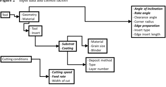
For a turning experiment, input data (conditions and geometry of cut) are depicted in Figure 2. Among all these variables, a choice has been conducted and represented in Figure 2. Indeed, after a dialogue between the industrial, the tool manufacturer and by taking into account results provided by researches on similar alloys. These chosen variables are represented in Figure 2 in dark and bold characters.
Figure 1 Experimental set up and chosen input data (see online version for colours)
Tool ‐ Geometry
‐ Material
‐ Angle of inclination : 0° ‐ Rake angle : 0° to 20° ‐Edge preparation : Honing and
Chamfer ‐ Tool ‐ Insert ‐ Substrat ‐ Coating ‐ Material : Carbide ‐ Grain size : Micro grain ‐ Blinder : Cobalt ‐ Deposit method : PVD ‐ Type : TiN and TiAlN ‐ Layer number : 1 (monoloayer) Cutting conditions
‐ Cutting speed : Define with Material Tool Pair ‐ Feed rate : range between 0.1mm/rev to 0.3 mm/rev ‐ Width of cut : 5 mm
Figure 2 Input data and chosen factors Tool ‐ Geometry ‐ Material ‐ Angle of inclination ‐ Rake angle ‐ Clearance angle ‐ Corner radius ‐ Edge preparation ‐ Insert type ‐ Edge insert length ‐ Tool ‐ Insert ‐ Substrat ‐ Coating ‐ Material ‐ Grain size ‐ Blinder ‐ Deposit method ‐ Type ‐ Layer number Cutting conditions ‐ Cutting speed ‐ Feed rate ‐ Width of cut 3 Cutting forces 3.1 Cutting speed
To define the cutting speed influence, we have used the French standard NF-E66-520-4. This standard presents a methodology to determine the minimum cutting speed Vc,min.
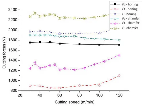
The minimum cutting speed is used in industry to characterise the machinability of particular alloys. For the tests, a radius edge and a chamfer edge have been used. Figure 3 illustrates the cutting forces according to cutting speed. The cutting force (F) is defined in two components. The first component (Fc) represents the cutting force dropped on cutting
speed direction (Figure 1). The thrust force (Ft) is parallel to the feed rate (Figure 1). In
these experiments, the cross sectional area of cut is equal to 1 mm2, so the specific cutting force is equal to cutting forces.
The Vc,min is defined at the value corresponding to the lowest specific cutting force.
For the two edge preparations, this value is difficult to identify clearly. We can define a minimum cutting speed at around 60 m/min. For this speed, the specific cutting force is the lowest. However, a wear appears rapidly and the tool is immediately failed. A notch and chipping occur after only six seconds of machining. For that reasons, we have defined, for our tests an optimal range between 30 m/min and 50 m/min. In these cutting speeds, the wear can be controlled.
The Figure 3 depicts that the cutting forces are not influenced by the cutting speed for a range between 30 and 80 m/min. For a value higher at 80 m/min, there is an increasing of Ft component. The two components seem to become equal for a high cutting speed. An
increasing of cutting speed increases the strain rate in the shear plan. So, the shear flow stress in primary and secondary plan increase. However, the cutting speed values are low and the thermal softening effect get with high values does not appear. The thermal softening effect can reduce the effective flow stress and results a decreasing of cutting forces. For Ti-5-5-5-3 machining, this effect is too difficult to get.
We can explain the poor variability of cutting force by the high Ti-5-5-5-3 mechanical properties. A higher cutting speed increases the effective strain rate and the cutting temperature. For standard material, the increasing of temperature reduces stress. However, the Ti-5-5-5-3 keep its mechanical properties in high temperatures. Hence, the cutting forces not decrease with cutting speed cutting speed increasing.
Figure 3 Cutting forces according to cutting speed and edge preparation (see online version for colours)
3.2 Rake angle
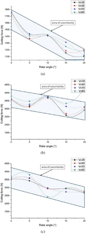
The Figure 4 shows the cutting force according to rake angle for three edge preparations [H0.04 (Figure 4(a) and H0.08 [Figure 4(b)] are the radius edge preparations. C0.15 [Figure 4(c)] is the chamfer edge preparation). The Figure 4 depicts that the increasing of rake angle decreases the cutting force. The observations are made on uncertainty area. This is the trend of cutting forces for all cutting speed. The reduction is only linear for the lowest edge preparation. In this case, the variation from 0° to 20° generates 35% decreasing cutting forces. With a bigger edge preparation a dead zone appears behind edge preparation. In this zone, the strain rate is very low. This phenomenon can explain the plot for the other edge preparation. Saglam et al. (2007) illustrates the cutting force reduction by a better edge penetration in material. A high rake angle generates a shear angle increasing and so a reduction of cutting force. This phenomenon can be illustrated by the Oxley and Hasting (1977) model.
To conclude, the rake angle choice must be a compromise between a cutting force reduction and a better tool mechanical aspect. An increasing of rake angle reduce the tool wedge angle and so the insert mechanical strength. The Ti-5-5-5-3 specific cutting force is higher than steel one.
Figure 4 Cutting forces according to rake angle, cutting speed and edge preparation (a) honing 0.04 mm (b) honing 0.08 mm (c) chamfer 0.15 × 20° (see online version for colours)
(a)
(b)
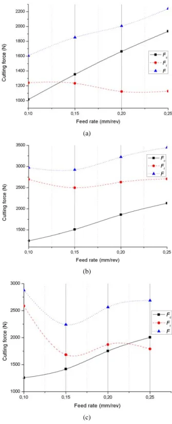
3.3 Cutting edge preparation
Three edge preparations have been used for these tests: two honed radius edge (0.04 and 0.08 mm) and a chamfer edge (0.15 mm). Two observations can be made from these experiments. First, Figure 5(a), Figure 5(b) and Figure 5(c) show the relationship between resultant force and edge preparation. The lowest cutting force is obtained with the sharpest edge tool Figure 5(a). The highest one appears with the highest honed radius edge Figure 5(b). With a sharp edge the tool penetration is better and generates a reduction of cutting force. Moreover, a dead metal zone appears behind edge preparation. In this zone, the strain rates are very low generating a very high stress. Karpat and Ozel (2008a) demonstrate that increasing of honed edge radius generates higher effective stress and so higher cutting forces.
In comparison with some other materials, there is a difference. In steel machining, the difference obtained with the two types of edge preparations is not so important. This difference can be explained by the Ti-5-5-5-3 mechanical properties and the machining effective stress. In steel machining, the cutting speed is higher than in Ti-5-5-5-3 machining. The mechanical properties and thermal properties of steel permit to get thermal effect softening. The effective stress decreases and so the cutting force are reduced. In Ti-5-5-5-3 machining, the poor thermal properties and the cutting conditions do not permit to get thermal softening effect. Movahhedy et al. (2002) explains that dead metal zone is removed with the increasing of cutting speed (Vc > 500 m/min) and a
cutting force reduction appears.
The influence both of edge preparation and undeformed chip thickness modify the cutting force direction (equation 1). The cutting force direction is the ratio between the components. c t F F μ= (1)
For a chamfered edge, the Figure 5(c) depicts that the evolution of the two components is the same if the undeformed chip thickness is less that 0.22 mm/rev. When feed rate is higher than 0.22 mm/rev, Fc values became the highest. For the smallest edge honed
radius, Ft is the lowest when feed rate is lower than 0.13 mm/rev or three times the edge
preparation. When feed rate exceeds this value, Fc became the highest. For the 0.08 mm
edge honed radius, Ft is always superior. However, for the two components the slopes are
different (Figure 5). So, Figure 5 depicts that the direction can be modified but for a high feed rate or a high ratio between feed rate and cutting edge.
Movahhedy et al. (2002) explain that when undeformed chip thickness is less than cutting edge preparation the material is trapped under the edge preparation. The chamfer or honed radius becomes the principal cutting face. So, the cutting process becomes an over cut face. In this new process, the dead metal zone effect is predominant and creates an effect on Ft. When feed rate is upper than width of cutting edge preparation, the dead
metal zone becomes cutting face tool and the cutting geometry is modified. In this case,
Fc becomes higher compared at Ft. This configuration is always true in steel machining.
The reduction of cutting edge tool improves the tool penetration and reduces the dead metal zone. So, the cutting forces are low. Fang and Wang (2005) show that transition is according to cutting speed and chamfer width.
Figure 5 Cutting forces according to feed and cutting edge preparation (a) honing 0.04 mm (b) honing 0.08 mm (c) chamfer 0.15 × 20° (see online version for colours)
(a)
(b)
To conclude, the lowest cutting force is obtained with the smallest edge preparations. The using of a bigger edge honed radius edge increases the cutting force. We note an increase of over 50%. With a chamfer edge, the cutting forces are higher but allow a better control of cutting force direction.
3.4 Feed rate
There is a linear relationship between feed rate and cutting resultant. The increasing is function of cutting undeformed chip section. These observations are the same with the classical material like steel or titanium alloys (Ti-6-4) where cutting force is the product between undeformed chip section and specific cutting force. The increasing of specific cutting force is function to mechanical properties. For Ti-5-5-5-3 machining, the cutting force is higher than steel according to the mechanical properties.
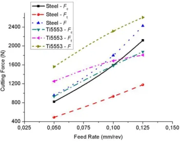
3.5 Comparison between process machining of steel and Ti-5-5-5-3
We have chosen to compare Ti-5-5-5-3 and steel machining. This comparison has not physical sense because chip formation mechanisms are quite different. But, this work is made in industrial context and it’s important to understand the difference between the new and the old landing gear machining process. This comparison allows us to understand the phenomena obtained in titanium alloy machining. The steel used is a non treated 300 M steel. The 300 M steel is used in old landing gear. The comparison is based on Merchant model. And the tests have been made with a minimal cutting edge preparation.
First, the tests depict that the cutting force obtained in Ti-5-5-5-3 machining are always the highest (Figure 6). These tests have shown also an effective primary shear plan shear stress similar in both materials. The difference is the cutting force direction (equation 1) which is the result of friction and effective shear stress. For steel, it’s always higher than 1.5. For Ti-5-5-5-3 machining, the value varied and can be less than 1.
To conclude, Ti-5-5-5-3 machining is very sensitive to cutting edge preparation and feed rate. These parameters modify the cutting force and especially its direction. Compared to steel, these influences are very important. In turning, these phenomena are not so important compared to milling where the surface roughness can be modified by the tool deflexion.
4 Cutting temperatures
The thermal conductivity and the heat capacity of Ti-5-5-5-3 are poor. Ezugwu and Wang (1997) demonstrate that 70% of heat is conducted in tool in Ti-6-4 machining. This value is caused by the poor titanium alloys thermal conductivity. Compared to Ti-6-4, the Ti-5-5-5-3 alloys thermal properties are quiet the same. We can think that Ezugwu and Wang (1997) conclusion can be the same for Ti-5-5-5-3 machining.
Moreover, the low thermal conductivity and the high mechanical properties do not allow the chip segmentation. Especially when the yield stress is high at 800°C. Poulachon et al. (2002) shows the chip segmentation formation is function of material deformation. An analysis can be achieved from (Poulachon et al., 2002). The large deformations area leads to an increase in temperature, which reduces the strength and increases the material ductility. For Ti-5-5-5-3, the combination of low thermal and high mechanical characteristics does not allow this softening even at high temperatures.
The tests have shown that friction forces are higher than Ti-6-4 machining. Whereas, the effective flow stress in primary shear plan remains the same between Ti-6-4 machining and Ti-5-5-5-3 machining. The distributed heat source is also different.
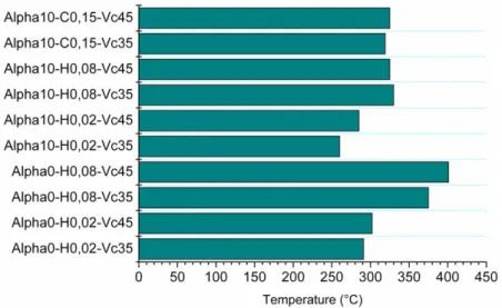
4.1 Cutting speed
Whatever the cutting edge preparation and the rake angle, the highest temperature is observed for the maximum cutting speed (Figure 7). A cutting speed increasing leads a highest strain rate and highest chip velocity. So, the cutting temperature depends on these values, we can observe an increasing of temperature.
4.2 Rake angle
Whatever the cutting edge preparation the lowest temperature is obtained with the maximal rake angle (10°) (Figure 7). The rake angle increasing reduces the effective shear angle and friction force. Oxley and Hasting (1977) demonstrate in their model that the cutting temperature is function of shear flow stress, friction force, chip velocity and shear velocity. In fact, whatever the cutting speed, a cutting forces decreasing reduce the cutting temperature.
4.3 Cutting edge preparation
We have seen that the combined effect of cutting edge preparation and feed rate modify the machining process. To limit the cutting edge preparation effect, all tests have been made with a feed rate that is two times the cutting edge width. The lowest temperature is obtained with the minimal cutting edge and the highest temperature with the maximal
edge preparation. In using an equal factor between cutting edge width and feed rate for all tests, the undeformed chip section is different for each one.
Karpat and Ozel (2008a, 2008b) show that the difference between the two types of cutting edge preparation is not the cutting temperature but the distribution. They demonstrate that the raising of cutting edge preparation increases the cutting force, the cutting temperature and the heat transfer section. So, the heat is also modified, the cutting tool temperature is constant but the heat source is different. The cutting temperature is according to strain rate and cutting force then the maximal temperature is obtained with the highest cutting edge preparation. Figure 7 shows that the highest temperature is obtained with the biggest radius edge preparation. With this one, the temperature is increased of 25% for a cutting force which is two times higher. The smallest temperature appears with the sharpest cutting edge preparation.
To conclude, the decrease cutting edge reduces the cutting temperature and the tool chip area. The lowest temperature is obtained with the sharpest cutting edge preparation. Use a minimal cutting edge can enable us to reduce cutting force and cutting temperature. These observations can be used to control wear in titanium machining. Moreover, by reducing the cutting edge preparation, and so, the heat transfer section, enables us to keep heat in cutting zone and to obtain the thermal softening effect.
However, the thermocouple is placed at 0.3 mm from cutting edge. The observed temperatures are very high compared to steel cutting temperatures. This difference can be explained by the higher mechanical properties that increase the cutting temperature. But also, by the poor thermal conductivity that allows a rapid heat conducted into the tool.
Figure 7 Tool temperatures after eight seconds (see online version for colours)
5 Wear of tools
The goal of this section is to define the tool failure modes generated when machining the Ti-5-5-5-3 alloy. A set of experiments was conducted with two different cutting edge preparations and different cutting speed.
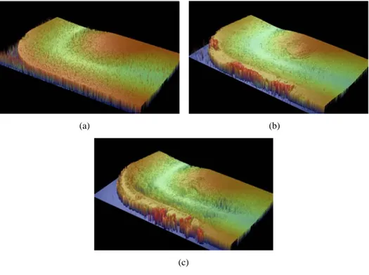
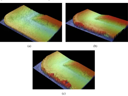
For the two edge preparations, Figure 8 and Figure 9 illustrate the three steps where wear of tool occurs. For chamfered edge tool, edge geometry is strongly modified. The edge preparation disappears and is replaced by a smooth surface [see Figure 8(b) and Figure 9(b). This first mode of wear is caused by the abrasive process of cutting. Indeed, when machining, the friction of the chip not segmented with the cutting edge draws away coating particles. However, this phenomenon is less existent when using with honed edge tool. Indeed, this leads to a reducing of the cutting forces, so the sliding force on the cutting face and the grinding phenomenon decrease. Furthermore, this first mode appears quickly and its length depends on coating and the cutting conditions. The experiments were shown that this first mode represents 10% of the tool life.
The second mode of wear observed is a built-up edge [see Figure 8(c) and Figure 9(c)]. This built-up edge is created rapidly after the first wear mode. In general, built-up edge is a wear mode observed when machining ductile materials. However, the elongation of Ti-5-5-5-3 alloy is equal to 2%. Works conducted by Fang and Dewhurst (2005) have proved that the built-up edge apparition can be closely related to the temperatures and slip stress on the tool-chip interface. We have shown that machining Ti-5-5-5-3 alloy leads to sliding force higher. Thus, knowledge of the sharing of the cutting force into normal and tangential forces permits us to control this wear mode.
Built-up edge is not a stable phenomenon and its presence is related to cutting process. It increases cutting forces and cutting temperature. Obviously, these phenomena will cause an increasing of stresses; hence, built-up edge will be extracted. This extraction will be accompanied with some particles of the insert. A progressive destruction of the cutting edge will be observed since the built-up edge is welded on the cutting face.
Figure 8 Wear modes for chamfered edge (see online version for colours)
(a) (b)
Figure 9 Wear modes for honed edge (see online version for colours)
(a) (b)
(c)
As opposed to Arrazola et al. (2008), no flank wear was occurred. The non-existence of this wear mode can be explained by the mechanical properties of the Ti-5-5-5-3 alloy (poor ductility and strength mechanical resistance) and the direction of the cutting force. Indeed, no contact is possible between the machining surface and the flank tool. Nevertheless, we can see some burning marks on the flank owing to high cutting temperature.
To summarise, failure modes of tools when machining the Ti-5-5-5-3 alloy are different from failure modes of tools when machining other titanium alloys. As opposed to results found in our work, many researchers have reported that machining titanium alloys leads to some wear modes: notches wear, crater wear and flank wear. This difference can be explained by preponderant friction phenomena on one hand and by strength mechanical properties of the Ti-5-5-5-3 alloy on the other hand.
In this first work, the wear mode analysis is based geometrical analyse. To understand all wear phenomena, a MEB analysis must be made. With this, we can explain the physical and chemical aspects.
6 Conclusions
This paper has showed that machining Ti-5-5-5-3 alloy lead cutting forces superior to other material. The optimal choice found is to use tool with sharp edge, a rake angle = 20° and a feed value superior to edge preparation. In order to have an acceptable tool life and durable cutting process, the cutting speed is chosen to be between 30 and 50 m/min. Machining Ti-5-5-5-3 alloy leads important cutting temperatures
values (similar to those provided by high speed machining processes). However, the high mechanical properties of Ti-5-5-5-3 alloy do not permit to benefit of these high temperatures in order to obtain the thermal softening. Moreover, the heat flow rate is shared differently compared with other materials (about 70% of heat is conducted in tool when machining titanium alloys).
Concerning wear, machining Ti-5-5-5-3 alloy generates different wear modes of tools from other titanium alloys or Ti-5-5-5-3 alloy none treated. Three steps were identified. The first one represents the elimination of edge preparation. During the second step, a built-up edge appears. Progressively, cycles of creation/extraction of this built-up edge contribute to destruction of the cutting edge. Yet, no flank wear was observed.
Only the first level relating the input data (cutting conditions and geometry of cut) and answers (wear of tool, forces and cutting temperatures) has been studied. The second level (interactions between phenomena of wear, forces and cutting temperatures) and the third level (forces, cutting temperatures and wear modify the geometry of cut that have influence on answers of the machining process) will be studied in future work. In order to define the optimal tool geometry and cutting conditions, a new experiment tests have to be done by considering the result tendencies provided by this paper.
Acknowledgements
This work was carried out within the context of the working group Manufacturing 21 which gathers 11 French research laboratories. The topics approached are as follows: • the modelling of the manufacturing process
• the virtual machining
• the emerging of new manufacturing methods. References
Arrazola, P.J., Garay, A., Iriarte, L.M., Armendia, M., Marya, S. and Le Maitre, F. (2008) ‘Machinability of titanium alloys (Ti6Al4V and Ti555.3)’, Journal of Materials Processing
Technology.
Corduan, N., Himbert, T., Poulachon, G., Dessoly, M., Lambertin, M., Vigneau, J. and Payoux, B. (2003) ‘Wear mechanisms of new tool materials for Ti6Al4V high performance machining’,
CIRP Annals – Manufacturing Technology, Vol. 52, No. 1.
Deshayes, L. (2007) ‘Analysis of an equivalent tool face for the cutting speed range prediction of complex grooved tools’, Journal Materials Processing Technology, Vol. 190, pp.251–262. Ezugwu, E.O. and Wang, Z.M. (1997) ‘Titanium alloys and their machinability – a review’,
Journal Materials Processing Technology, Vol. 68, pp.262–274.
Fang, N. and Dewhurst, P. (2005) ‘Slip-line modelling of built edge formation in machining’,
International Journal of Mechanical Sciences, Vol. 47, pp.1079–1098.
Fang, N. and Wang, Q. (2005) ‘The effects of chamfered and honed tool edge geometry in machining of three aluminum alloys’, International Journal of Machine tools & Manufacture, Vol. 45, pp.1178–1187.
Jones, N.G., Dashwood, R.J., Dye, D. and Jackson, M. (2008) ‘Thermomechanical processing of Ti-5Al-5Mo-5V-3Cr’, J. Material Sciences & Engineering, in press.
Karpat, Y. and Ozel T. (2008a) ‘Mechanics of high speed cutting with curvilinear edge tools’,
Journal Machine Tools & Manufacture, Vol. 45, pp.195–208.
Karpat, Y. and Ozel, T. (2008b) ‘Analytical and thermal modelling of high-speed machining with chamfered tools’, Journal of Manufacturing Science & Engineering, Vol. 130.
Manjunathaiah, J. and Endres, W.J. (2000) ‘A new model and analysis of orthogonal machining with an edge radiused tool’, Journal of Manufacturing Science & Engineering, Vol. 122, pp.384–390.
Movahhedy, M.R., Altintas, Y. and Gadala, M.S. (2002) ‘Numerical analysis of metal cutting with chamfered and blunt tools’, Journal of Manufacturing Science & Engineering, Vol. 124, pp.178–188.
Nabhani, F. (2001) ‘Wear mechanisms of ultra-hard cutting tool materials’, Journal of Materials
Processing Technology, Vol. 115, pp.402–412.
Nouari, M., Calamaz, M. and Girot, F. (2008) ‘Mécanismes d’usure des outils coupants en usinage à sec de l’alliage de titane aéronautique Ti-6Al-4V’, C.R. Mécanique, Vol. 336, pp.772–781. Oxley, P.L.B. and Hasting, W.F. (1977) ‘Predicting the strain rate in the zone intense shear in
which the chip is formed in machining from the dynamic flow stress properties of the work material and the cutting conditions’, Proc. R. Soc., London.
Pawade, R.S., Suhas, S.J., Brahmankar, P.K. and Rahman, M. (2007) ‘An investigation of cutting force and surface damage in high-speed turning for Inconel 718’, Journal of Materials
Processing Technology, Vols. 192–193, pp.139–146.
Poulachon, G., Moisan, A.L. and Dessoly, M. (2002) ‘A contribution to the study of the cutting mechanisms in hard turning’, Mécaniques et Industrie, Vol. 3, pp.291–299.
Ranganath, S., Campbell, A.B. and Gorkiewocz, D.W. (2007) ‘A model to calibrate and predict forces in machining with honed cutting tool or insert’, International Journal of Machine Tools
& Manufacture, Vol. 47, pp.820–840.
Ren, H. and Altintas, Y. (2000) ‘Mechanistic of machining with chamfered tools’, Journal of
Manufacturing Science & Engineering, Vol. 122, pp.550–559.
Saglam, H., Yaldiz, S. and Unasacar, F. (2007) ‘The effect of tool geometry and cutting speed on main cutting force and tool tip’, Materials & Design, Vol. 28, pp.101–111.
Yen, Y-C, Jain, A. and Altan, T. (2004) ‘A finite element analysis of orthogonal machining using different tool edge geometries’, Materials Processing Technology, Vol. 146, pp.72–81.