Université de Montréal
Study of cox1 trans-splicing in Diplonema papillatum
mitochondria
par Yifei Yan
Département de biochimie Faculté de médecine
Université de Montréal
Faculté de médecine
Ce mémoire intitulé:
Study of cox1 trans-splicing in Diplonema papillatum mitochondria
présenté par :
Yifei Yan
a été évalué par un jury composé des personnes suivantes :
Dr. Pascal Chartrand Dre. Gertraud Burger Dre. Léa Brakier-Gingras
TABLE OF CONTENTS
TABLE OF CONTENTS ... 3
LIST OF FIGURES AND TABLES ... 5
LIST OF ABBREVIATIONS ... 6
ACKNOWLEDGEMENTS ... 8
RÉSUMÉ ... 9
ABSTRACT ... 10
1. INTRODUCTION ... 11
1.1INTRON TYPES AND DISTRIBUTION IN NATURE ... 11
1.1.1 tRNA and/or archaeal introns ... 11
1.1.2 Group I and group II introns ... 11
1.1.3 Spliceosomal introns ... 16
1.2INTRON TRANS-SPLICING ... 18
1.2.1 Spliceosome-dependent trans-splicing ... 18
1.2.2 Discontinuous group II intron trans-splicing... 18
1.2.3 Discontinuous group I intron trans-splicing ... 18
1.3TRANS-SPLICING IN DIPLONEMA MITOCHONDRIA ... 19
1.3.1 What is Diplonema papillatum? ... 19
1.3.2 Mitochondrial genome ... 21
1.3.3 Unusual genome organization and gene expression in D. papillatum mitochondria. ... 21
1.3.4 D. papillatum mitochondrial cox1 trans-splicing differs from all known trans-splicing processes ... 22
1.4.TRANS-SPLICING COULD BE ASSISTED BY HELPER RNAS ... 24
1.4.1 Does anti-sense mRNA assist trans-splicing?... 24
1.4.2 Guide RNA-directed editing in the mitochondria of kinetoplastids ... 24
1.4.3 The discovery of gRNA in trypanosome RNA editing ... 24
1.4.4 The trypanosome RNA editing machinery ... 27
1.4.5 Experimental demonstration of gRNA function in kinetoplastid mitochondria ... 29
2. WORKING HYPOTHESES FOR THE PROJECT ... 31
3. MATERIALS AND METHODS ... 32
3.1DNASE I TREATMENT OF TOTAL RNA ... 32
3.2TOBACCO ACID PHOSPHATASE (TAP) TREATMENT OF RNA ... 32
3.3POLYNUCLEOTIDE KINASE TREATMENT OF RNA ... 32
3.4RNA CIRCULARIZATION ... 32
3.5REVERSE TRANSCRIPTION ... 33
3.6PCR... 33
4.3LONG ANTI-SENSE RNA DOES NOT EXIST ... 45
4.4RT-PCR AND AMPLICON SEQUENCING IDENTIFIED SEQUENCES THAT MATCH GRNA PROFILES 47 4.5TRANS-SPLICING WAS NOT OBSERVED THE PRELIMINARY IN VITRO ASSAY ... 54
5. DISCUSSION ... 57
5.1POPULATIONS OF MITOCHONDRIAL GRNAS MAY EXIST ... 57
5.2MODULES 4 AND 5 SEQUENCING RESULTS SUGGEST THAT TRANS-SPLICING AND EDITING SHARE COMMON STEPS ... 57
5.3KINETIC INFERENCE OF MODULES 4 AND 5 TRANS-SPLICING ... 59
5.4D. PAPILLATUM GRNAS MAY NOT CONFORM TO THE “RULES” ... 59
5.5BIOLOGICAL RELEVANCE OF TRANS-SPLICING IN D. PAPILLATUM ... 64
5.6FUTURE STUDIES ... 65
6. REFERENCES... 66
7. APPENDICES ... 72
APPENDIX 1:HYPOTHETICAL GRNA SEQUENCES FOR COX1 TRANS-SPLICING ... 72
APPENDIX 2.PRIMERS USED IN THE RT-PCR ... 75
APPENDIX 3.ANTI-SENSE SEQUENCES DETECTED WITH CONVERGENT RT-PCR ON COX1 MODULE JUNCTIONS ... 77
APPENDIX 4.SUMMARY OF UNKNOWN SEQUENCES FROM RT-RCR ON CIRCULARIZED TOTAL RNA TARGETING GRNA ... 78
APPENDIX 5.OUTPUTS OF MFOLD PROGRAM FOR CALCULATION OF THE SECONDARY STRUCTURES OF SELECTED CLONES ... 79
List of Figures and Tables
Figure 1. Secondary structure of a typical mitochondrial group I intron ... 13
Figure 2. Typical secondary structure of a group II intron ... 15
Figure 3. Similarity between U6 snRNA and DV of group II introns ... 17
Figure 4. Cell morphology of D. papillatum. ... 19
Figure 5. Schematic representation of the phylogenetic position of D. papillatum ... 20
Figure 6. Two mitochondrial chromosomes of D. papillatum ... 22
Figure 7. Gene structure of cox1 in D. papillatum mitochondria ... 23
Figure 8. Common features of the pre-mRNA-gRNA duplex in kinetoplastids ... 26
Figure 9. A schematic representation of U-insertion editing in kinetoplastids ... 28
Figure 10. Working hypotheses on trans-splicing of cox1 ... 31
Figure 11. A flow chart of the fractionation process of the cell lysate ... 36
Figure 12. Capping of total RNA of D. papillatum in the presence of radio-labeled GTP ... 41
Figure 13. Difference between different PNK enzymes for subsequent circularization of RNA ... 42
Figure 14. Sequencing RNA species that contain M4/5 junctions ... 44
Figure 15. Experimental design of RT-PCR to detect long anti-sense RNA ... 45
Figure 16. RT-PCR results of anti-sense RNA detection. ... 46
Figure 17. Experimental design of RT-PCR to detect partial sequences of gRNAs . 48 Figure 18. Reverse transcription of RNA using normal RT primer (CDS primer) and Clontech® SMART primer (SMART II A oligonucleotide) ... 49
Figure 19. An illustration of the principle of in vitro assay for cox1 trans-splicing . 54 Figure 20. Trans-splicing in vitro using radio-labeled modules ... 55
Figure 21. Proposed model of how the six Us are added between Module 4 and Module 5 ... 58
Figure 22. Potential gRNAs with secondary structures for six Us between M4/M5 in trans-splicing... 61
Figure 23. Modules of mRNA may act as gRNA ... 62
Figure 24. Secondary structure of cox3-module 1 (clone dp9356) ... 63
Table 1. Sequencing results of hypothetical gRNAs from RT-PCR with specific primers converging towards the module junctions ... 51 Table 2. Sequencing result of circularized hypothetical gRNA from RT-PCR with
List of Abbreviations
A6: mitochondrial ATPase subunit 6
AMV: avian myeloblastosis virus ATP: adenosine triphosphate
BLAST: basic alignment search tool cDNA: complementary DNA
cox1: cytochrome c oxidase subunit 1
CTP: cytosine triphosphate
CYB: apocytochrome b
DNA: deoxyribonucleic acid dNTP: deoxy-ribonucleotides DTT: dithiothreitol
EBS: exon binding site
EDTA: ethylenediaminetetraacetic acid eIF: eukaryotic translation initiation factor EtBr: ethidium bromide
gRNA: guide RNA
GTP: guanosine triphosphate IBS: intron binding site
IPTG: isopropyl β-D-1-thiogalactopyranoside
IRIC: l’Institute de recherche en immunologie et en cancérologie (IRIC) LB: lysogeny broth
mRNA: messenger RNA
nad5: NADH dehydrogenase subunit 5
ND7: NADH dehydrogenase (mitochondrial complex I) subunit 7
NEB: New England Biolabs PCR: polymerase chain reaction PNK: polynucleotide kinase
Prp8: pre-mRNA processing factor 8 homolog (S. cerevisiae) RNA: ribonucleic acid
rns: small subunit ribosomal RNA
rRNA: ribosomal RNA RT: reverse transcription SAM : S-adenosyl-methionine SL-RNA: spliced leader RNA snRNA: small nuclear RNA
snRNP: small nuclear ribonucleoprotein sRNA: small RNA
TAP: tobacco acid phosphatase tRNA: transfer RNA
TUTase: terminal U transferase UTP: uridine triphosphate UTR: untranslated region
ACKNOWLEDGEMENTS
I would like to thank Dr. Gertraud Burger for giving me the wonderful opportunity to study as a master student under her supervision. Her extraordinary vision and
unparalleled patience helped me through out the study. I thank my parents for their altruistic support even during their difficult times. I thank Shona Teijeiro, Lise Forget, and the rest of the lab for their day to day assistance on my project. I thank Dr. Franz Lang for his guidance and motivation during the preparation of the manuscript for our publication in Trends in Genetics. I thank Dr. Pascal Chartrand, Dr. Normand Brisson and their students for generously lending me the lab equipments and helping me on experimental techniques; and I thank Dr. Luc DesGroseillers, the parrain, for useful advices on my study and my project.
RÉSUMÉ
Diplonema papillatum est un organisme unicellulaire qui vit dans l’océan. Son génome mitochondrial possède une caractéristique spéciale: tous les gènes sont brisés en de multiples fragments qui s’appellent modules. Chaque module est codé par un chromosome différent. L’expression d’un gène exige des épissages-en-trans qui
assemblent un ARN messager complet à partir de tous les modules du gène. Nous avons précédemment montré que le gène cox1 est encodé dans neuf modules avec six Us non encodés entre le module 4 et le module 5 de l’ARN messager mature [1]. Nous n’avons identifié aucune séquence consensus connue de site d’épissage près des modules. Nous spéculons qu’un ARN guide (gRNA) a dirigé l’épissage-en-trans du gène cox1 par un mécanisme qui est semblable à l’édition d’ARN par l’insertion/la suppression des Us chez les kinétoplastides, le groupe sœur des diplonémides. Nous avons trouvé que les six Us sont ajoutés au bout 3’ de l’ARN d’une façon semblable à ceux ajoutés par le TUTase lors de l’édition de l’insertion des Us chez les kinétoplastides. Nous avons construit des profils de gRNA de l’épissage-en-trans avec les expressions régulières basé sur notre connaissance des gRNAs dans l’édition d’ARN chez les kinétoplastides. Selon la complémentarité partielle entre le gRNA et les deux modules adjacents, nous avons généré des amorces pour RT-PCR visant à détecter des séquences qui sont assorties à un des profils de gRNA. Une expérience pilote in vitro n’a pas permis de reconstituer l’épissage-en-trans des modules 3, 4, et 5, suggérant que nous devons améliorer nos techniques.
Mots clés: Diplonema papillatum, mitochondrie, cox1, épissage-en-trans, ARN guide, kinétoplastides, RT-PCR
ABSTRACT
Diplonema papillatum is a single cellular organism that lives in the ocean. Its
mitochondrial genome possesses a special feature: all genes are fragmented in multiple pieces that are called modules and each module is encoded by a different chromosome. Expression of a gene requires trans-splicing that successfully assemble a full-length mRNA from all modules of the gene. It was previously shown that the cox1 gene is encoded in nine modules that are all located on different chromosomes; moreover, a stretch of six non-encoded Us exist between Module 4 and 5 in the mature mRNA [1]. No consensus sequence of known splicing sites was identified near the modules. We speculate that trans-splicing of the cox1 gene is directed by guide RNAs (gRNAs) via a mechanism that is similar to U-insertion/deletion editing in kinetoplastids, the sister group of diplonemids. We have detected populations of small RNA molecules that could come from mitochondrial. We found that the six Us were added to the 3’ end of Module 4 in a similar way to the Us added by the TUTase in kinetoplastid U-insertional editing. Sequence profiles of possible trans-splicing gRNAs were constructed in regular expressions based on our knowledge of known gRNAs in kinetoplastid RNA editing. According to the complementarity between the gRNA and the two adjacent modules, primers were designed for RT-PCR that aims to detect gRNA sequences. Among the results, we identified sequences that match or partially match the gRNA profiles. A pilot in vitro assay did not reconstitute trans-splicing of module 3, 4 and 5, suggesting that further technical improvements are needed.
Key words: Diplonema papillatum, mitochondrion, cox1, trans-splicing, guide RNA, kinetoplastids, RT-PCR
1. INTRODUCTION
Splicing originally refers to the process that removes non-coding sequences, introns, which interrupt the coding sequences from the primary transcripts so that the coding sequences can correctly join and form a contiguous messenger RNA ready for translation. In order to better study trans-splicing, a variation of the conventional intron-splicing, we will briefly recapture our knowledge about conventional splicing.
1.1 Intron types and distribution in nature
Introns are sequences present in the primary transcript that are subsequently removed and thus absent from the mature RNA molecule. Introns are categorized into tRNA or archaeal introns, group I introns, group II introns, and spliceosomal introns. 1.1.1 tRNA and/or archaeal introns
Despite their name, the phylogenetic distribution of tRNA and/or archaeal introns is ubiquitous, in Eukarya, Archaea and Bacteria. In bacteria, tRNA introns are self-splicing [2]; while in archea and eukaryotes, tRNA self-splicing requires a cascade of enzymes including endonucleases that specifically recognize the splice sites [3]. Such recognition depends on the conserved structural features of the tRNA such as the anticodon loop and the bulge-helix-bulge motif (BHB). Eukaryotic nucleus-encoded tRNA introns are always located between the first two nucleotides 3’ to the anticodon.. The cleavage site is determined by the distance from the highly conserved structural features of the mature molecule, the 3’ end of the anticodon stem [4]. Archaebacterial tRNA introns are found in additional locations of the tRNA: in the anticodon stem, the anticodon loop [5], or the extra arm [6]. The recognition of intron/exon boundaries requires special sequences and tertiary structures at the boundary, where a bulge-helix-bulge structure is formed by a stem of four base-pairs flanked by two 3-nt loops [7-9].
1.1.2.1. Group I introns
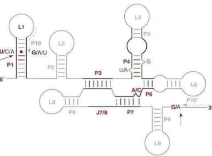
Group I introns are found in the nucleus and organelles of diverse eukaryotes such as fungi, plants and numerous protist groups. They are absent from mitochondria of animals, except for several early diverging metazoa such as corals, sponges, sea anemones, and placozoan (for references, please see [16]). Group I introns are rarely found in Eubacteria and bacterial phages and are completely absent in Archea [17-19]. The secondary structure of group I introns usually consists of approximately 10 paired regions (P1-10) that fold the molecule into a conserved secondary structure [20] (Fig. 1). Although in some cases particular paired regions may be absent in a group I intron, the sequences surrounding P1, P3, P4, P6 and P7 constitute the “intron core” of the
secondary and tertiary structure. Group I introns are removed from the precursor RNA sequence by a two-step mechanism. In the first step, an external guanine nucleotide attacks the 5’ splice site and causes a cut in the phosphate backbone, then it is covalently bound to the newly cut site on the intron. The second step involves the attack of the 3’ splice site by the 3’ end OH of the cleaved exon from step 1. This results in the ligation of the exons and the release of the intron sequence [17].
Figure 1. Secondary structure of a typical mitochondrial group I intron
Black lines indicate the conserved intron core. Pairings (P), loops (L) and junctions (J) are numbered according to conventions that emphasize secondary structure. Universally conserved structural elements are shown in red, while variable portions are shown in gray. The minimum number of conventional base pairs (A-U, G-C and G.U) in helices is shown in red. One base pairing in P7 (broken) is absent in several instances. It should be noted that J3/4 and J3/7 vary in size and have, therefore, not been listed as part of an invariant core structure. P10 and P10′ are the two halves of a helical interaction. This figure is adapted from [14].
1.1.2.2 Group II introns
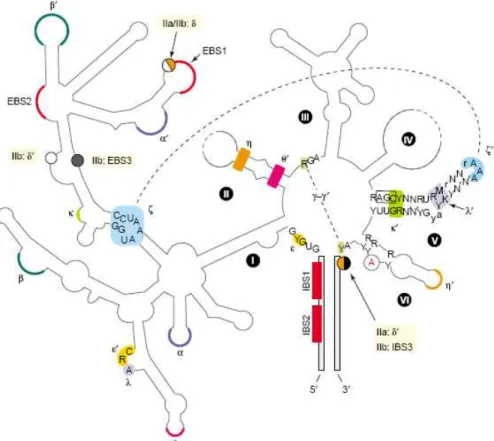
Group II introns preferentially occur in the organelles of land plants, fungi, and protists [18]. They were rarely identified in Archaea and Bacteria (for reviews see [14, 15]) and they are absent from the mitochondrial DNA of metazoa. The secondary structure of a group II intron usually consists of six helical domains, extending from a central hub, and denoted as domains I to VI [21]. Though, the most distinctive feature of group II introns is domain V, which contains an AGC triad in the paired region crucial for the catalytic activity of the ribozyme [22], and a GNRA-tetraloop motif (N denotes any nucleotide and R stands for A or G). This GNRA motif is highly conserved and can be reliably used as a landmark sequence for group II introns [14]. The molecular process of group II intron splicing involves two successive transesterification reactions and it uses the 2’-OH of an internal and bulged adenosine residue to initiate the attack on the 5’ splice site [18]. As the consequence, the group II intron that undergoes splicing is excised as a lariat structure [23]. Both steps of the reaction are reversible; however, the reverse reaction of the second step is much slower than the forward one under physiological conditions, rendering the reverse-splicing an inefficient process. The reverse-splicing process can be manipulated by altering the conditions to be as efficient as the forward one [24], and interestingly, the reverse reaction works efficiently with DNA targets as well [25].
Figure 2. Typical secondary structure of a group II intron
A Group II intron core structure shows six domains (DI–DVI) that extend from a central hub (flanking exons in grey). Uppercase letters in domain V reflect >90%, lowercase 80–90% conservation; Y =
pyrimidine; R = purine; M = A or C; K = G or U; N–N′ = canonical basepair. Domain V is shown as 9 bp + 5 bp separated by a dinucleotide bulge. The boxed nucleotidtes (AGC) are among those essential for catalysis as determined by detailed site-directed mutagenesis and self-splicing in vitro. The bulged A in domain VI is shown in red. Tertiary interactions are shown by color-coded Greek symbols, two of which are illustrated by dashed lines (namely γ–γ′ and ζ–ζ′). EBS = exon binding site (red), IBS = intron binding site (red). Flanking exons are shown in grey and the bulged “A” in DVI is shown in red.
1.1.3 Spliceosomal introns
Spliceosomal introns are common in nuclear genes of eukaryotes, but absent from mitochondrial and chloroplast genes, as well as eubacterial and archaeal genes. Exon-intron junctions of eukaryotic spliceosomal Exon-introns are highly conserved, with most of them having GU at the 5’ boundary of the intron and AG at its 3’ boundary. A minor class of introns in yeast, vertebrates and invertebrates has different splice site sequences, that is, AUAUCUU at the 5’ end and CAC at the 3’ end [26, 27]. The spliceosome is a ribonucleoprotein complex that contains five uridine-rich small nuclear RNAs, or snRNAs, designated as U1, U2, U4, U5 and U6. The snRNAs are highly conserved and range between 60 to 300 nt in length. Splice sites are recognized by small nuclear
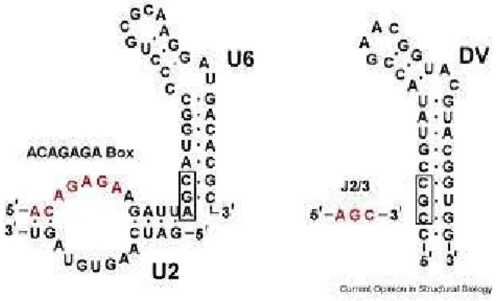
ribonucleoprotein particles (snRNPs) in the spliceosome, which are complexes formed by about 150 protein factors with 6 snRNAs in humans [28]. It was shown that U1 and U2 recognize the 5’ and 3’ splice junctions, respectively, via an ATP- and temperature-dependent base-pairing mechanism [29, 30]. Together with U4-U6 and U5 snRNAs, the snRNPs align the active sites and form the catalytic core that carries out splicing (for a review see [31]). In vitro studies showed that intron removal by the spliceosome follows a two-step reaction mechanism similar to that of group II introns [32, 33]. Further, sequence and structure similarities exist between the U6 snRNA and the domain V (DV) of group II introns [34, 35]. Figure 3 depicts the similarity between group II intron and the U6 RNA. Due to the parallelism between the two systems, it was suggested that U2 and U6 alone could form the catalytic center of the spliceosome (for review, see [36]). However, the spliceosome likely differs from the group II intron in the composition of the active site, because a protein called Prp8 was consistently found within the active site of spliceosome [37], while no protein was found to be associated with the active site of DV of the group II intron. Hence, refined structural data and improved techniques that overcome the difficulties imposed by the spliceosome assembly process are still needed to test whether its catalytic activity is truly a protein-free process.
Figure 3. Similarity between U6 snRNA and DV of group II introns
The U6 RNA is on the left and the domain V of the Oceanobacillus iheyensis group II intron is on the right. The catalytic triad (boxed) is located at the base of the stem loop structures, with the two-nucleotide bulge spaced five base pairs away. The ACAGGA box (red) may form base triple interactions with the triad of the U6 snRNA, analogous to that observed between J2/3 and domain V [34].
1.2 Intron trans-splicing
Trans-splicing originally refers to the collaborative removal process involving two separate primary transcripts that each holds a moiety of an intron; consequently, the two independent transcripts are joined to generate a new continuous RNA molecule. A few variations of trans-splicing were discovered during the past two decades and they fall into the following categories: spliceosome-dependent, discontinuous group II, and
recently, group I intron trans-splicing.
1.2.1 Spliceosome-dependent trans-splicing
This process was first demonstrated in the nucleus of Trypanosoma brucei, where a 39-nt RNA processed from a 140 nt-long “Spliced Leader RNA” (SL-RNA) is added to the 5’ end of every pre-mRNA molecule in order to generate a translatable mRNA. Hence the process was referred to as “spliced-leader type” trans-splicing [38, 39]. The corresponding spliceosome has a somewhat different snRNP composition from that of conventional cis-splicing spliceosomes [40]. SL-trans-splicing was also discovered in the nucleus of worms [41], Euglena [42], and Diplonema [43]. More recent studies showed that non-SL-type trans-splicing of nucleus-encoded genes in human depends on
spliceosomes [44, 45].
1.2.2 Discontinuous group II intron trans-splicing
Trans-splicing that involves discontinuous group II introns [46] was first observed in chloroplasts of land plants [47, 48]. In vitro group II intron trans-splicing was first demonstrated by Konarska’s group, showing that intermolecular RNA-RNA
hybridization increases the efficiency of trans-splicing significantly [49]; later on, protein factors were found to be required for this process in vivo [50].
1.2.3 Discontinuous group I intron trans-splicing
Very recently, cases of naturally occurring group I trans-splicing were discovered, all of them in mitochondria. The first reported instance is in the placozoan animal
Trichoplax adhaerens [16] (Appendix 6) and the others in the lycophyte moss Isoetes engelmannii [51] and the green alga Helicosporidium [52]. In vitro trans-splicing of discontinuous group I introns was previously demonstrated possible for mammalian cells and the molecular requirements are thought to be similar to those of cis-splicing [53].
1.3 Trans-splicing in Diplonema mitochondria
None of the above models explains the trans-splicing phenomenon that we observed in Diplonema mitochondria (Kiethega et al., submitted). Based on knowledge gained from our preliminary studies, we postulate that Diplonema mitochondria represent a new type of trans-splicing, as we detailed below.
1.3.1 What is Diplonema papillatum?
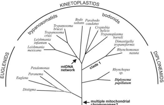
D. papillatum is a single-celled bi-flagellated eukaryote that lives in the ocean (Fig. 4). Diplonemids, together with kinetoplastids and euglenids form the phylum of Euglenozoa, which are characterized by discoidal mitochondrial cristae, as well as a distinctive architecture of the flagellar and feeding apparatus [54, 55]. Based on
molecular phylogeny, diplonemids and kinetoplastids diverged after euglenids [56, 57]. Figure 5 depicts a schematic phylogenetic tree of Euglenozoa.
A.
B.
Figure 5. Schematic representation of the phylogenetic position of D. papillatum
Schematic phylogenetic tree of Euglenozoa is taken from [1]. The topology is taken from studies by Simpson and coworkers [56, 58] , where bootstrap support is significant for both the common ancestry of Euglenozoa and the diplonemids and kinetoplastids. The branching order within euglenids is tentative. Arrows indicate, as proposed in this report, the time points in evolutionary history when multiple
mitochondrial chromosomes and mtDNA networks arose in Euglenozoa. Note that Parabodo caudatus was previously designated Bodo caudatus.
1.3.2 Mitochondrial genome
The mitochondrion is the “power plant” of a cell in terms of generating most of the ATP molecules required for cellular function. The genes encoded by the
mitochondrial genome are involved in a relatively constant set of biological processes that are localized to the mitochondria. The functions of these genes include: respiration, oxidative phosphorylation, and translation. Less frequently, mitochondrial genes are involved in protein import/maturation, transcription, and RNA processing. The median of mitochondrial genome sizes is 30 kbp when animals are included; excluding animals, the median is 50 kbp. The largest mitochondrial genome is found among plants, with a size of 2400 kbp in the family of Cucurbitaceae [59].
1.3.3 Unusual genome organization and gene expression in D. papillatum mitochondria.
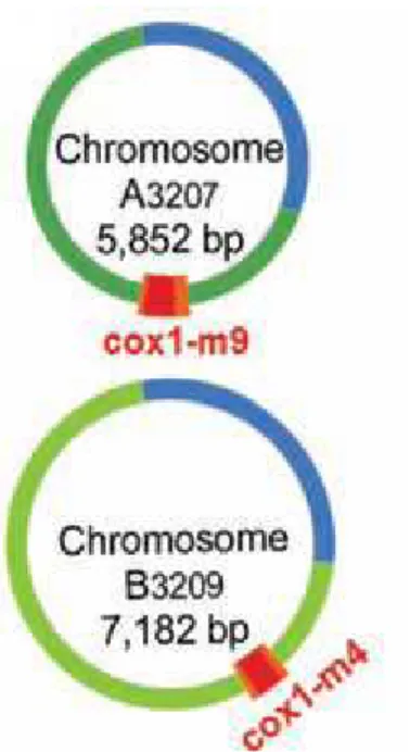
Akin to trypanosomes and euglenids, Diplonema contains one mitochondrion per cell [60]. The total size of the D. papillatum mitochondrial genome is probably around 600 kbp. It contains two types of circular chromosomes designated as class A and class B of sizes around 6.2 kbp and 7.2 kbp, respectively. Chromosomes of the same class are quasi-identical in sequence in the “constant region” that spans 95% of the whole length of the chromosome. The residual 5% consists of the “cassette” which holds a coding region and adjacent non-coding unique sequence. It is the cassette that distinguishes individual chromosomes from one another (Fig. 6).
Figure 6. Two mitochondrial chromosomes of D. papillatum
The blue and green arcs together represent the constant regions. Blue region sequences are identical for all chromosomes and green region sequences are identical among chromosomes of the same class. The cassette consists of a gene module (red) and the flanking regions (orange) [61].
All mitochondrial genes coding for rRNAs, cytochrome oxidase subunits, NADH dehydrogenase subunits, etc., are found to be fragmented into several pieces and each cassette of a chromosome holds one piece termed a “module” [62]. While contiguous and complete DNA regions coding for these genes were not detected either in nuclear or in mitochondrial DNA, the corresponding contiguous mature transcripts were found. This implies that the assembly of modules occurs at the RNA level, i.e., involves trans-splicing [1, 61].
1.3.4 D. papillatum mitochondrial cox1 splicing differs from all known trans-splicing processes
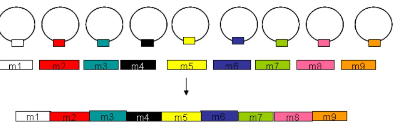
Marande and Burger [61] showed that mitochondrial cytochrome c oxidase subunit 1 (cox1) gene is fragmented into nine pieces and its mRNA is assembled from nine pieces of separately transcribed primary RNAs (Fig. 7). This trans-splicing process does not resemble any of the previously reported cases after detailed bioinformatic analyses were conducted (Kiethega et al., submitted). Firstly, in the regions adjacent to the coding modules, none of the highly conserved spliceosomal intron motifs mentioned earlier was detected. Secondly, these regions do not contain tRNA intron sequences.
Thirdly, none of the conserved group I or group II intron sequence motifs was detected in these regions. Lastly, the fact that module junction sites differ from all known insertion points of organellar introns further diminishes the possibility of the presence of
discontinuous group I and II introns. The assembly of RNA modules into mRNA proceeds apparently by a new mechanism.
Figure 7. Gene structure of cox1 in D. papillatum mitochondria
The cox1 gene is encoded in nine individual pieces on different chromosomes. Circles represent different chromosomes and colored rectangles are the gene modules of cox1. The nine modules are assembled at the RNA level into a translatable mRNA.
1.4 Trans-splicing could be assisted by helper RNAs 1.4.1 Does anti-sense mRNA assist trans-splicing?
A mechanism was recently identified in the ciliate Oxytricha trifallax where larger RNA molecules are used as templates to direct the assembly process of genomic DNA sequences [63]. Such long RNA template could also be present in D. papillatum but to direct the assembly of RNA modules. Alternatively, Diplonema trans-splicing may be directed by small guide RNA (gRNA) in a way similar to mitochondrial RNA editing in kinetoplastids. The process and machinery involved in ciliate DNA splicing are not known; in contrast, kinetoplastid RNA editing has been intensively studied during the past 20 years.
1.4.2 Guide RNA-directed editing in the mitochondria of kinetoplastids Kinetoplastids include several parasitic genera, such as Leishmania and Trypanosoma. The mitochondrial genome of trypanosomes consists of circular DNA molecules, termed maxicircles (14 to 40 kbp) and minicircles (1.0 to 1.4 kbp). There is a single type of maxicircle, present in dozens of copies, which encodes typical
mitochondrial genes, and hundreds of different types of minicircles, present in thousands of copies, which encode gRNA [58]. Genes encoded on maxicircles were often found to lack initiation or termination codons; in some cases, they include frameshifts. RNA editing corrects these shortcomings by inserting or deleting precise numbers of uridine (U) residues at distinct positions. Such precision is achieved through the help of the gRNAs (for a review, see [64]).
1.4.3 The discovery of gRNA in trypanosome RNA editing
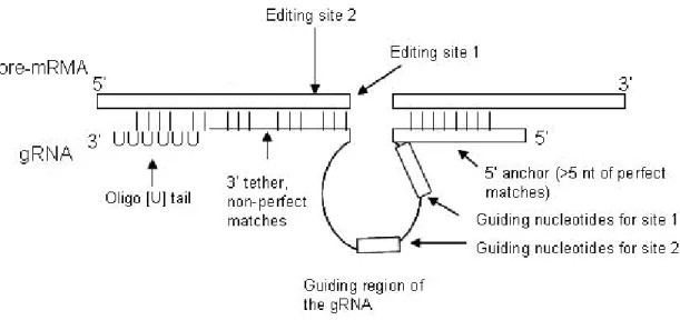
The Simpson’s group radio-labeled small RNA molecules isolated from the trypanosome mitochondria and used them as probes in Southern blot against membrane bound mitochondrial DNA. They detected regions on the mitochondrial minicircles to be gRNA-encoding. Further confirmation was obtained by cloning and sequencing these RNAs and testing them in vitro [65]. Since then, a plethora of gRNA molecules were identified in kinetoplastid mitochondria assisting the editing events. These gRNAs were reported to contain a 5’ anchor region that is usually around 5-12 nt in length and pairs perfectly with the pre-mRNA downstream of the edited site to hold the pre-mRNA in
position (Fig. 8). RNA duplex stabilization involves not only Watson-Crick but also G-U base pairing. The central part of the gRNA is the “guiding region” and it appears in two forms: in insertion editing, the guiding region contains additional “guiding nucleotides” that act as a template and they will pair with the newly inserted Us; in deletion editing, the guiding region contains no nucleotide that pairs with the Us in the pre-mRNA and the un-matched Us will be deleted. The guiding region could be as long as 25-35 nt and it may direct editing at multiple neighboring sites on the pre-mRNA [66]. Non-guiding nucleotides may also exist in the guiding region (curved lines in the “guiding region” depicted in Figure 8). They do not bind to pre-mRNA and they can form a bulge when gRNA initially hybridizes to mRNA. Base-pairing may occur within the bulge itself and secondary structures can form; however, they do not affect editing [67]. Upon the
completion of editing, the guiding nucleotides must pair with the edited sequence and the non-guiding nucleotides would pair with the nucleotides next the editing site. The
anchoring region at the 3’ of the gRNA is also called a “tether”, which pairs in many cases with about 11 nt of purine-rich sequence in the pre-mRNA further to its 5’ end (5 to 24 nt away from the editing site) [66]. In the 3’ tether of the gRNA, mutations that
increases base-pairing stability with 5’ moiety of the mRNA decreases the formation of edited products [68]. At the very 3’ end of the gRNA, there is usually an oligo-U tail of 5-24 nt that binds to the purine-rich region in pre-mRNA further upstream, providing additional stabilization.
In summary, the following features are common for gRNAs to mediate the recognition of the editing site: 55-75 nt in size, perfect 5’ base-pairings between gRNA and mRNA, single stranded guiding nucleotides and single stranded region of pre-mRNA, 3’ end tethering of the pre-mRNA (Fig. 8). The gRNA sequences found in
Figure 8. Common features of the pre-mRNA-gRNA duplex in kinetoplastids
The top strand represents the mRNA with the 5’ end on the left. The bottom strand represents the gRNA with the 5’ end on the right. The square-shaped sequence represents sequences that are coding or
complementary to coding sequence. The line represents sequences that are non-coding. The gRNA in this figure encodes two U-insertion sites. The editing of the two sites proceeds in the 3’ to 5’ direction along the pre-mRNA.
1.4.4 The trypanosome RNA editing machinery
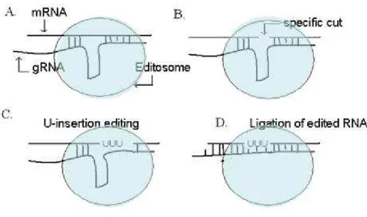
Experimental evidence shows that U-insertion/deletion editing in trypanosomes mitochondria involves endonucleolytic cleavage and ligation. A multi-protein complex of about 20S, called editosome, carries out RNA editing in a stepwise fashion [64]. Specific recognition of editing sites on the target pre-mRNA via the help of gRNA molecules is the first step of editing (Fig. 9A). The gRNA molecule contains nucleotides
complementary to the sequence both upstream and downstream of the editing site. The guiding nucleotides are between the complementary nucleotides on both ends and they mismatch the mRNA at the nucleotides to be edited. A cleavage will be made by an endonuclease of the editosome on the pre-mRNA at the 3’ of the first base that is not paired to the gRNA’s 5’ anchor [69] (Fig. 9B). This creates a nick on the pre-mRNA, exposing the 3’ OH group of the cleaved strand. In U-insertion editing, the next step is that TUTase adds a stretch of Us to the exposed 3’ end of the pre-mRNA, then excess number of Us will be trimmed by a U-exonuclease to the length specified by the guiding nucleotides in the guide RNA; in the case of U-deletion editing, only a U-exonuclease will be involved in this step to cut the excessive Us [70-72] (Fig. 9C). The U-removal process leaves a phosphate group at the 3’ end of the upstream moiety of the pre-RNA, which renders the 3’ end non-ligatable. Once the template sequence matches the target sequence, a phosphatase removes the phosphate group [73] and the 3’ of the edited site is religated to the 5’ by an RNA-ligase [74] (Fig. 9D). After the editing of a given site is completed, the gRNA is displaced by a helicase, and the editosome proceeds to the next editing site in the 5’ direction along the pre-mRNA. In summary, under the direction of gRNA molecules, the trypanosomal RNA editosome executes the following enzymatic activities: RNA endonuclease, TUTase, phosphatase, RNA ligase and helicase.
Figure 9. A schematic representation of U-insertion editing in kinetoplastids
The mRNA is on top and the guide RNA is at the bottom. The ellipsoid shape represents the editosome complex. An endonucleolytic cut is made in the mRNA at the 5’ end of the nucleotide that pairs with the last nucleotide of the 5’ anchor region of the gRNA (see Fig. 8 for the 5’ anchor region of gRNA). Multiple Us are subsequently added to the 3’ end of the cut and trimmed to the exact length that is specified by the complementary nucleotides in the gRNA. The nick is then ligated and upon completion of editing, the mRNA perfectly pairs with the gRNA at the editing site.
1.4.5 Experimental demonstration of gRNA function in kinetoplastid mitochondria As soon as RNA editing was discovered in kinetoplastids, several in vitro systems were set up attempting to reproduce this process.
1.4.5.1 In vitro systems at the organelle level
Isolated mitochondrial vesicles from T. brucei were shown to incorporate 32 P-UTP into endogenous RNAs post-transcriptionally [75]. A similar observation was made using a mitochondrial extract of L. tarentolae [76]. These experiments confirmed the outcome of U-insertion editing; however, they only monitored the general incorporation of radio labeled nucleotides, hence are not sufficient to study the U-insertion editing mechanism.
1.4.5.2 In vitro systems based on a mitochondrial extract
The mitochondrial extract based system has been refined to test specific hypotheses on requirements of RNA editing. A study of gRNA-dependent editing was reported for both U-insertion and U-deletion in vitro [77]. In a T. brucei system, synthetic gRNA was added and the U-insertions and U-deletions occurred at the expected editing sites of A6 mRNA [78-80]. Despite the low efficiency of the T. brucei in vitro system, the signals of the labeled intermediates are strong enough to allow detection. A similar study was conducted with a L. tarentolae system with exogenously supplied synthetic gRNA, where blockage of the 3’-OH of the U-tail of the gRNA, which is required for the hypothesized transesterification reaction that supplies the Us, did not have any effect on editing. This result showed that transesterification was not involved in the transfer of Us [81]. Using the mitochondrial extract-based in vitro system, gRNA-independent editing was also studied. For the mitochondrial genes CYB and ND7 in L. tarentolae, primer extension assay revealed that the 3’ UTR of the mRNA can fold back and form a short
for their roles. For example, in T. brucei, two ~57 kDa and one ~50 kDa bands were isolated as part of the minimal editing complex. The 57 kDa complex was later purified and identified as an RNA ligase [84] and the 50 kDa remains to be characterized. In a less efficient system, L. tarentolae, Aphasizhev’s group affinity-purified proteins involved in RNA-binding from the mitochondrial extract to better understand their roles using biochemical assays [85].
To sum up, the establishment of in vitro systems allowed the determination of the roles that individual components play in the editing process. Further, different features of the gRNAs and mRNAs can be tested for their necessity in editing.
Our previous studies in D. papillatum demonstrated the presence of a stretch of six non-encoded Us at the junction of Modules 4 and 5 [61]. This suggests that a
trypanosome type U-insertion editing machinery exist in Diplonema mitochondria. In fact the functions available in the hypothetical editosome would suffice the requirements of trans-splicing in Diplonema mitochondria, given a properly designed gRNA that directs the ligation of the transcripts of two adjacent modules.
2. WORKING HYPOTHESES FOR THE PROJECT
From the above, we can formulate two working hypotheses regarding trans-splicing in Diplonema mitochondria:1. Small gRNAs exist and help assemble every two neighboring module transcripts. Such gRNAs should comprise sequences complementary to the junctions of two neighboring modules (Fig. 10A)
2. Alternatively, a complete antisense mRNA (referred in the following as “long gRNA”) exists and acts as a template to direct the simultaneous assemblage of all module transcripts of a given gene (Fig. 10B).
A.
3. MATERIALS AND METHODS
3.1 DNase I treatment of total RNARNase-free DNase I from Roche® was used to digest the residual DNA present in the total RNA extracted from D. papillatum according to the manufacturer’s instructions. Briefly, 10 µL of 1 µg/µL of total RNA, 5 µL of 10X reaction buffer provided by the supplier, and 0.5 µL of 10 units/µL of DNase I were combined in a total reaction volume of 50 µL. The reaction mixture was incubated at 37 °C for 15 minutes. The enzyme was heat-deactivated at 75 °C for 10 minutes. The reaction mixture was phenol-chloroform extracted and ethanol-precipitated.
3.2 Tobacco Acid Phosphatase (TAP) treatment of RNA
TAP was purchased from Epicentre Biotechnologies® and treatment conditions followed instructions of the commercial supplier. Briefly, the reaction mixture contained 20 µg of total RNA from the previous step, 1X reaction buffer, and 2.5 units of the enzyme in a total volume of 20 µL. Incubation was carried out at 37 °C for one hour. The RNA was phenol-chloroform extracted and ethanol-precipitated, then resuspended in 20 µL of RNase-free water.
3.3 Polynucleotide Kinase treatment of RNA
T4 Polynucleotide kinase (PNK) was used following the instructions of the commercial supplier, New England Biolabs (NEB). Briefly, the reaction mixture contained 20 µg of RNA, 1X reaction buffer, 1 mM ATP, and 10 units of T4 PNK enzyme in a final volume of 50 µL. The reaction was incubated at 37 °C for one hour. The enzyme was inactivated at 65 °C for 20 minutes.
3.4 RNA circularization
Circularization of RNA was achieved by RNA ligation at low concentration using T4 RNA ligase from Roche®. Briefly, the ligation mixture contained 20 ng/µL of RNA, 1X reaction buffer, 0.1 mM ATP, 10 ng/µL of BSA, and 0.15 unit/µL of the ligase. The total reaction volume depended on the amount needed and we kept the total volume under 20 µL. The reaction mix was incubated at 16 °C overnight. RNA was phenol-chloroform extracted and ethanol precipitated. RNA was resuspended at 200 ng/µL in RNase-free water.
3.5 Reverse Transcription
We used avian myeloblastosis virus (AMV) reverse transcriptase from Roche® for this reaction. The reaction mix contained 50 ng/µL of RNA, 0.5 µM of the primer, 1X of the first strand reaction buffer, 100 µM DTT, 1mM of each dNTP, 1 unit/µL of the enzyme. The reaction was usually carried out in a final volume of 20 µL. The RNA and the primers were pre-incubated at 72 °C for 2 minutes, then other ingredients were added and the total reaction mix was incubated at 42 °C for 1 hour.
For convergent RT-PCR across the modules, the following primers were used in the RT: M1/M2: dp142 M2/M3: dp88 M3/M4: dp146 M4/M5: dp129 M5/M6: dp150 M7/M8: dp84 M8/M9: dp154
For divergent RT-PCR, the following primers were used in the RT: M1/M2: dp144 M2/M3: dp138 M3/M4: dp148 M5/M6: dp152 M7/M8: dp141 M8/M9: dp155
in the same batch of reactions, a gradient PCR program was set up on the PTC-200
Peltier Thermal Cycler from MJ-Research PCR machine. The thermal cycles were: 96 °C for 2 minutes, 88 °C for 1 minute, 96 °C for 20 seconds, annealing temperature for 20 seconds, 72 °C for 1 minute, go to step 3 (96 °C for 20 seconds) 24 times, 72 °C for 5 minutes, and 4 °C forever.
For convergent PCR across the modules, the following primers were used: M1/M2: dp142, dp143 M2/M3: dp88, dp80 M3/M4: dp146, dp147 M4/M5: dp129, dp109 M5/M6: dp150, dp151 M7/M8: dp84, dp85 M8/M9: dp154, dp41
For divergent PCR, the following primers were used: M1/M2: dp144, dp145 M2/M3: dp138, dp139 M3/M4: dp148, dp149 M5/M6: dp152, dp153 M7/M8: dp141, dp140 M8/M9: dp155, dp156 3.7 DNA end-repair and purification
Two units of T7 DNA polymerase (NEB) and 2 units of Klenow enzyme (NEB) were added to the PCR mix as soon as the PCR cycles finish so that blunt ends were produced for cloning. The mix was incubated at 12 °C for 30 minutes. The products were visualized on a 0.8% agarose gel for their sizes. A low melting 0.8% agarose gel was used for gel purification of the PCR products of certain size ranges. DNA was either electro-eluted from the gel or extracted with QiaBeads™ gel-purification kit from Qiagen®. The reaction was stopped by heating at 65 °C for 2 minutes.
T4 PNK form Roche® was used to phosphorylate the gel-purified PCR products. The reaction mix contained final concentration of 10 ng/µL of DNA, 1 mM of ATP, 1X reaction buffer, and 1 units/µL of the enzyme. The reaction mix was incubated at 37 °C for 30 minutes.
Using T4 DNA ligase, the phosphorylated product was ligated at 14 °C overnight into a blunt-end linearized and de-phosphorylated vector, pBFL6cat, that carries blue-white selection markers (B.F. Lang, unpublished). The reaction mix contains10 ng/µL of DNA (including the insert and the vector), 1 mM of ATP, 1X ligase buffer, and 1 unit/µL of T4 DNA ligase. The amount of insert DNA to be added was calculated to satisfy the molar ratio between the insert and the vector of 2:1.
Transformation of 1/10 of the ligation mix into E. coli cells (DH5α strain) was carried out according to protocols outlined in Molecular Cloning by Maniatis [86]. Bacteria were plated onto LB-agar plate (contained 5 µg/mL chlroramphenicol, 5 µg/mL tetracycline, 10 uM IPTG, and 40 µg/mL X-GAL) for blue-white selection. For the inserts whose sizes were known to be small, both blue and white colonies were picked because we would not miss clones that contained in-frame small inserts that failed to disrupt the lacZ gene function. Each picked colony was placed into a well in the 96-well culture block from SARSTEDT®. After overnight growth in LB (contained the same ingredients as the LB-agar plate except for the X-Gal and IPTG), plasmid DNA was extracted using the Qiagen 96-well mini-prep kit and was resuspended in 40 µL volume in 96-well Corning® plates at -20 °C.
3.9 Sequencing reactions
BigDye® Terminator v3.1 Cycle Sequencing Kit from Applied Biosystems was used for the sequencing reaction. From the DNA plate, 1 µL of each plasmid
3.10 Sequence analysis
Sequencing results were downloaded from the website of the sequencing facility. After unzipping the files, we used in-house Perl scripts to retrieve sequences and remove the vector sequences from them. The resulting sequences were combined in a multi-sequence FASTA file. Using local BLAST we queried the primer multi-sequences against the sequencing results, and we identified the positions of the primers in each sequence. Using the MotSearch program, we looked for the hypothesized gRNA sequences that matched the profiles in Appendix 1. D. papillatum mitochondrial DNA sequences of around 250 kbp and mitochondrial cDNA sequences of about 20 kbp were also queried against the sequencing results. Results were organized in Excel files where the configuration of the sequences were categorized and counted.
3.11 D. papillatum cell culture and preparation of sub-cellular fractions
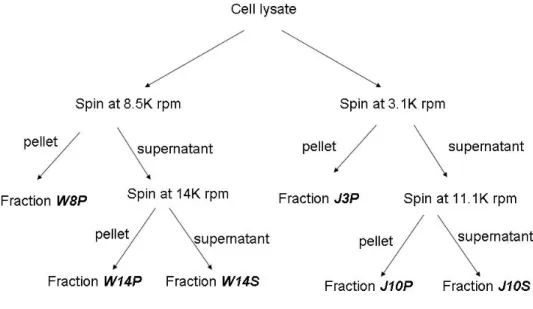
Figure 11. A flow chart of the fractionation process of the cell lysate
The left branch of fractionation followed the centrifugation speeds used by William Marande who previously worked on the project in the lab; hence, the fractions were designated with the prefix “W”. The fractionation scheme on the right was adapted from a whole-cell-extract preparation protocol on
mammalian cells used in Dr. Jerry Pelletier’s lab, hence the prefix “J”. The suffixes “P” and “S” represent the pellet and the supernatant, respectively.
Two liters of D. papillatum culture was grown to a density of 1.6X10⁶ cells/mL after approximately a week in 0.33% Instant Ocean, 0.1% bacto-tryptone, and 1% horse
serum. Cells were harvested at 6,000 rpm with a GSA rotor. Cell pellets were
resuspended in 1.5 volume of STE buffer (250 mM sucrose, 20 mM Tris of PH 7.9, and 2 mM EDTA) and let it sit for 10 minutes for proper mixing. The cell resuspension was then passed though a 22 gauge needle 10 times, and 60% of sucrose was added
immediately to the lysate in 6:50 volume ratio (e.g. 2.4 mL of 60% sucrose will be added to 20 mL of lysate). The lysate was then divided in two (Fig. 11): one was for the
preparation of a fraction called W8P following a protocol previously used in the lab [1], and the other one was for the preparation of the fraction called J10P using a modified centrifugation scheme. To make W8P , the cell lysate was divided into 1 mL aliquots in Eppendorf tubes and centrifuged at 8,500 rpm (7,650 g) in an Eppendorf Microfuge 5417C at 4 °C for 10 minutes to clear the lysate. The pellet portion was labeled as W8P, which would typically contain the Diplonema nucleus, and the supernatant portion was labeled as W8S. The W8S was futher centrifuged at 14,000 rpm (20,800 g) to precipitate the mitochondria in the Microfuge 5417C for 15 minutes. The pellet was labeled as W14P, which contains the mitochondria, and some of the microsomes and membranes, while the supernatant was labeled as W14S, which contains the rest of the membranes, ribosomal RNAs and proteins. For the other lysate, aliquots of 1 mL in eppendorf tubes were centrifuged in the microfuge at 4 °C for 10 minutes at 3,100 rpm (1,000 g) for 10 minutes. The first centrifugation is at a lower speed than the first fractionation scheme because the diplonemid mitochondria are known to be large. A slower speed will avoid precipitating mitochondria with nuclei during the first centrifugation. The supernatant was labeled J3S while the pellet was labled J3P. Further centrifugation was performed on J3S in the microfuge at 11,100 rpm (13,000 g) at 4 °C for 20 minutes, and the supernatant was labeled J10S, which contains membranes, proteins and ribosomal RNA, while the
Module 3, Module 4, Module 4 with six Ts, and Module 5 were amplified by PCR using primers that contained the T7 RNA polymerase promoter sequence at the 5’ end. Primers used were dp157-163 (Appendix B). The PCR products were run on an agarose gel and the corresponding bands were gel-purified and confirmed by sequencing. In vitro transcription was carried out following the instructions in the T7 RNA polymerase kit from NEB. The reaction contained 1X RNA polymerase buffer, 5 µL of 10 mg/mL BSA, 1.25 µL murine RNaseIn® (NEB), 2.5 µL of 10 mM ATP, CTP, and GTP, 1 µL of 10 mM UTP, 3 µL of α-32P-UTP (10 µCi/µL), 10 µL of 20 ng/µL DNA templates, and 1 µL T7 RNA polymerase in a total volume of 50 µL. The reaction was incubated at 37 °C for 2 hours, phenol-chloroform extracted and passed through a G-50 column. RNA was then washed and precipitated in 70% ethanol, resuspended in 10 µL of RNase-free water, and kept at -80 °C for future use.
3.13 In vitro trans-splicing assay
An in vitro trans-splicing experiment was performed by incubating a D. papillatum crude mitochondria-enriched extract, unlabeled total RNA, together with internally labeled cox1 RNA Module 3, 4 or 5. Two different crude extracts were used: W8P and J10P. Each in vitro reaction contained 25 mM of HEPES (PH 7.5), 5 mM magnesium acetate, 50 mM potassium acetate, and 1 mM DTT, 1 mM ATP, 15 µL of either one of the extracts, 0.6 µL of the NEB murine RNase inhibitor, 3 µL of the radio-labeled RNA substrate, and 1 µL of the total RNA (200 ng/µL) in a total volume of 30 µL. The reaction was incubated at 37 °C for 4 hours. Then RNA was phenol-chloroform extracted, and run on a 6% PAGE in 1X TBE, with 7M urea, at 5 V/cm for one hour then at 10 V/cm for five hours and 20 minutes. The gel was exposed to a film at -80 °C for 48 hours.
3.14 Capping reaction
Capping enzyme was ordered from the Epicenter® Biotechnologies. Briefly, each capping reaction contained 1X reaction buffer, 0.1 mM S-adenosyl-methionine (SAM), 1 unit/µL of RNAse inhibitor, 1 µCi/µL of α-32P-GTP from Perkin Elmer, 1 µg/µL of total RNA, and 0.4 units/µL of the ScriptCap™ enzyme. The capped RNA was phenol-chloroform extracted, ethanol-precipitated, and resuspended in 20 µL of RNase-free water.
3.15 Gel-purification of radio-labeled probes and Southern blot
A 12% polyacrylamide gel with 6M urea was used to separate the total labeled RNA. Labeled bands were cut out and soaked in the elution buffer (0.1% SDS, 0.5 M ammonium acetate, and 10 mM magnesium acetate) at 4 °C overnight. The elution was centrifuged briefly to rid of the residual polyacrylamide.
Meanwhile, total DNA was run on a 0.7% agarose gel in multiple lanes. A picture of the gel was taken under UV with a ruler. The gel was denatured in denaturing solution (1.5 M NaCl and 0.5M NaOH) for 15 minutes at 4 °C and then rinsed in neutralization solution (1.5 M NaCl, 0.5 M Tris of pH 7.5, and 1 mM EDTA) twice for 15 minutes at 4 °C. The gel was allowed to equilibrate with 10X SSPE (1.8 M NaCl, 0.1 M phosphate buffer of pH 7.7, and 10 mM EDTA) at 4 °C for 10 minutes. One hundred milliliter of phosphate buffer of pH 7.7 was prepared by combining 10.5 ml of 1 M NaH2PO4 and
89.5 ml of 1 M Na2HPO4. DNA in the gel was then transferred to a Hy-bond™
membrane overnight using 2 layers of Whatman™ filter paper and 3 cm of paper towels stacked underneath the membrane. The DNA sample lanes on the membrane were then cut so that each lane can be hybridized to a different probe. The membranes were pre-hybridized with degraded and denatured salmon sperm DNA in the hybridization buffer (1% SDS, 1.5X SSPE, 0.5% Denhardt’s reagent, and 0.1 mg/ml degraded salmon sperm DNA).
Denatured probes were then added to a fresh hybridization buffer and
hybridization was carried out at 65 °C overnight. The membranes were washed a few times using buffers with descending ionic strength. Humid membrane was then exposed to film for 48 hours.
4. EXPERIMENTAL RESULTS
4.1 Radio-labeling of mitochondrial RNA with capping enzyme
Guide RNAs of kinetoplastids involved in U-insertion/deletion editing are small RNA molecules encoded by mitochondrial DNA. We asked whether such a population of small RNAs exists in D. papillatum mitochondria as well. Employing an RNA capping method that was previously used in the study of trypanosomes [87], we intended to detect the existence of these small RNAs and locate their genes in the genome. The rationale of the approach is briefly described below.
In all eukaryotes, the 5’ triphosphate end of primary transcripts in the nucleus is modified by the RNA 5’-triphosphatase (RTP), RNA guanylyl transferase (RGT), and RNA (guanine-7-) methyltransferase (RNMT) [88, 89]. The cap structure is an inverted and 7-methylated guanine nucleotide that is connected via a 5’-5’ triphosphate bridge to the first guanine residue of the mRNA. It is often written as GpppRNA cap, or M7G cap. Other methylation positions are known while the inverted guanine is invariant among all cap structures. Capping of primary transcript, however, does not take place in the
mitochondria. Using a commercially provided capping enzyme that was engineered to combine RTP and RNMT activity, we intended to specifically radio-label the 5’ ends of all mitochondrial primary transcripts. Labeled RNAs were separated by electrophoresis and used as probes in Southern blot to identify their origin in the genome.
We have identified three major bands that were radio-labeled after running a polyacrylamide denaturing gel (Fig. 12). The very top band corresponds to the RNA molecules that did not enter the gel. We estimated sizes range of the labeled bands is between 50 to 300 nucleotides. Comparing to the EtBr stained unlabeled total RNA, we see that the RNA band at about 190 nt position could not be capped, while the top and bottom radio-labeled bands is not visible in EtBr staining.
A. B.
Figure 12. Capping of total RNA of D. papillatum in the presence of radio-labeled GTP
(A) Lane 1 and 2 contain 32P-labeled M3 and M5 by in vitro transcription in the presence of α-32P-GTP. Upper band corresponds to the in vitro transcription product and the lower smear probably corresponds to the partially degraded RNA. Lane 3 is the total RNA with 32P incorporated in the cap. Unlabeled total RNA (right-most two lanes) was run on the same gel and the lanes were cut to be visualized by ethidium bromide staining and UV light. A picture was taken with a ruler on the side, so that we can compare the bands to the radio-labeled ones. (B) Total RNA and 1Kb RNA ladder were electrophoresed side by side and visualized by ethidium bromide staining. The lowest band of the ladder corresponds to 200 nt.
Probably due to the low activity of the probes, Southern hybridization did not detect on which genome those RNA species are encoded.
4.2 Trans-splicing intermediates containing the Module 4 and 5 junction To confirm that trans-splicing proceeds accurately at the junction of Module 4 and 5, and to better understand how the six Us appear between these two modules, we
performed RT-PCR on circularized RNA molecules to capture RNA intermediates from the trans-splicing process. To circularize RNA molecules, we treated RNA with TAP enzyme and T4 PNK with 3’-phosphatase activity, followed by RNA auto-ligation at low concentration (Fig. 13).
Figure 13. Difference between different PNK enzymes for subsequent circularization of RNA
Mitochondrial transcripts in D. papillatum may have at their 5’ end a single phosphate (if processed) or a tri-phosphate (in primary transcript). At their 3’ end, they could have an -OH group or a phosphate group (in the newly added U-tail in trypanosome U-insertional editing). Some transcripts are phosphorylated at 3’ ends. When an RNA molecule with 3’-OH was treated with TAP and T4 PNK that lacks the 3’
phosphatase activity, the 5’ tri-phosphate was converted to a mono-phosphate and it was readily ligated by T4 RNA ligase (pathway on the left). For an RNA molecule that was phosphorylated at the 3’ end, the wild-type PNK (with 3’-phosphatase activity) was used for successful auto-ligation; otherwise, the RT-PCR could not proceed (pathway on the right).
The synthesis of cDNA was primed in Module 5 in the reverse direction from its 3’ end, and then three PCR reactions were carried out with different primer pairs. All primer pairs consisted of a primer that was located near the 3’ end of Module 5 in the
forward direction, and its counterpart was located near the 5’ end of Module 3, 4 or 5 respectively, in the reverse direction. All PCR products were pooled together before cloning into vectors. This was my first batch of sequencing (i62). The second batch (i65) of sequences was prepared from a different PCR: using the same cDNA, the primer in Module 3 was omitted in the PCR. We only intended to detect intermediates that contained Module 4 and Module 5 sequences so that we could better understand how trans-splicing took place at Modules 4 and 5 junction accompanying the insertion of six Us. Sequencing results of the first RT-PCR from 48 clones is summarized in panel A of Figure 14. Panel B contained sequencing results for the second batch of 96 clones of RT-PCR products targeting intermediates containing the M4/M5 junction. This batch was labeled “i65”. In both cases, no Module 5 with six Us attached to its 5’ end was detected and no Module 4 was found to be directly connected to Module 5. On the other hand, Module 4 was found to have six Us attached to its 3’ end with or without the adjacent modules. Module 4 with 5’ and/or 3’ non-coding regions were detected to be abundant in both cases, while “cleanly” processed Module 4 occurred only rarely.
A . B . ig u re 1 4 . S eq u en ci n g R N A s p ec ie s th a t co n ta in M 4 /5 j u n ct io n s 4 , M o d u le 4 c o d in g s eq u e n c e; M 4 + e x t, M o d u le 4 w it h 5 ’ an d /o r 3 ’ ex te n si o n ; M 4 + 6 T , M o d u le 4 w it h s ix T (U f o r R N A )s a tt ac h ed t o i ts 3 ’ e n d ; M 4 -n t, o d u le 4 w it h s o m e n u cl eo ti d es m is si n g ; M 5 , M o d u le 5 c o d in g s eq u e n ce o n ly ; M 5 + e x t, M o d u le 5 w it h 5 ’ a n d /o r 3 ’ ex te n si o n s fr o m t h e p ri m ar y t ra n sc ri p t; M 4 6 T + M 5 , M o d u le 4 a n d M o d u le 5 j o in ed t o g et h er w it h s ix T i n t h e b et w ee n ; M 4 + M 5 ( + T s? ), M o d u le 4 a n d M o d u le 5 a re j o in ed , b u t w h et h er t h er e a re s ix U s b et w ee n c a n n o t b e d et ec te d b y R T -P C R b ec au se t h e p ri m er s ch o se n d o n o t co v er t h is r e g io n ; M 3 -M 5 (+ T s? ), M o d u le 3 i s jo in ed w it h M o d u le 5 , b u t w h et h er er e is a M o d u le 4 w it h s ix T s in b et w ee n c an n o t b e d et ec te d i n t h is R T -P C R d u e to t h e p ri m er s c h o se n ; M 3 M 4 + 6 T , M o d u le 3 a n d M o d u le 4 a re j o in ed a n d er e ar e si x T s at ta ch ed a t th e 3 ’ en d o f th e M o d u le 4 ; 6 T + M 5 , th er e ar e si x T s at ta ch ed t o t h e 5 ’ en d o f M o d u le 5 ; M 4 + M 5 , M o d u le 4 a n d M o d u le 5 a re ir ec tl y l in k ed w it h o u t a n y th in g b et w ee n t h e m ; u n su re , th e se q u en ce s d et ec te d a re n o t le g ib le ; n o s eq u e n ce , se q u e n ce i s ei th er e m p ty o r th e re ad q u al it y i s to o w t o b e an al y ze d . F o r ea ch t y p e o f se q u e n ce d et ec te d , it s fr eq u en c y a m o n g t h e sa m e b at ch o f se q u en ce s is c o u n te d , as i n d ic at ed b y t h e y -a x is .
4.3 Long anti-sense RNA does not exist
If a long complementary RNA exists to direct the module assembly of the cox1 gene, then we should be able to identify RT-PCR products that span across multiple modules of the gene. In order to detect such long anti-sense molecule present at very low concentration, we performed a RT-PCR followed by a nested PCR reaction to enrich the product. Since shorter PCR products are favored in the reaction, we only aimed to amplify part of the hypothetical anti-sense RNA that spans across Module 5 and 9 (Fig. 15). We used for the positive control the same set of primers except for the RT primer which targets the sense RNA.
Figure 15. Experimental design of RT-PCR to detect long anti-sense RNA
A primer (green) in the anti-sense direction was used for reverse transcription. Following the reverse transcription, two rounds of PCRs were performed using nested primers shown here. The first PCR used the outer pair (in Modules 5 and 9) and the second round used inner pair (in Modules 6 and 8). As a positive control, a primer in the sense direction (in Module 9, red) was used for cDNA synthesis. Then the same two rounds of PCR were performed and we expected to amplify a region spans about 400 nt (between Module 6 and 8) on the mature mRNA. From left to right, the primers are: dp82, dp67, dp35, and dp38.
We focused on products that span Modules 5 through 9. As shown is Figure 16, the nested RT-PCR did not yield a product indicative for an anti-sense RNA molecule that spans across more than four modules (lane 1). The positive control (lane 2) showed that under the same experimental conditions, the mRNA was successfully detected for its
Figure 16. RT-PCR results of anti-sense RNA detection.
Lane 1: Detection of anti-sense of Modules 5 through 9. For reverse transcription of the antisense, a primer annealing in Module 5 was used. Primer pairs used in nested RT-PCRs flank Modules 5 and 9, then 6 and 8. Lane 2 (positive control): Reverse transcription of the sense mRNA between Modules 5 and 9, followed by nested PCR using the same primers as in Lane 1. Lanes 3-5: Negative controls of RT and both PCR reactions.
Hence, no long anti-sense RNA likely exists to direct the post-transcriptional assembly of the whole cox1 transcript.
4.4 RT-PCR and Amplicon Sequencing identified sequences that match gRNA profiles
If small gRNAs exist for module joining, we should be able to amplify the guiding nucleotides in the gRNA using primers complementary to the nucleotide sequences at the module borders. Three sets of RT-PCR were designed.
In the first set of experiments, we performed a reverse transcription (RT) reaction on the gRNA using a primer that was identical in sequence to the nucleotides at the 3’ end of Module 4 (green primer a in panel A of Fig. 17). In the subsequent PCR, we used the RT primer and a primer (green primer b in panel A of Fig. 17) that was identical to the reverse complementary sequence of the nucleotides at the 5’ end of Module 5. In the expected product we should detect the sequence of primer a, the guiding nucleotides of the gRNA, and the sequence of primer b. To be sure that the products do not come from ligation of the two primers, the primers were designed not to cover the last nucleotide of Module 4 and the first nucleotide of Module 5. If the RT-PCR product came from real amplification of RNA, we would detect the two uncovered nucleotides in the sequence of the product; otherwise, if the product came from the ligation of primers, those two
nucleotides would be absent. Similar primers were designed for the junctions of M1/M2, M2/M3, M3/M4, M5/M6, M7/M8, M8/M9. The same primers were used in the
amplification of the mRNA as a positive control (primer pair in red, panel A of Fig. 17). In the second set of RT-PCR experiments, instead of linear RNA, we used circularized RNAs as templates and diverging primers in the PCR to obtain sequences beyond the binding sites of the primers (panel B in Fig. 17). For each module junction, the primers were exactly complementary to the sequences of those used in the RT-PCR on linear RNA. For example, we used an RT primer (primer d, in green) that was
easily. Similar RT-PCRs were carried out upon junctions of M1/M2, M2/M3, M3/M4, M5/M6, and M7/M8.
Figure 17. Experimental design of RT-PCR to detect partial sequences of gRNAs
(A) The green primer a on the left-hand-side of the junction was used for reverse transcription of potential gRNA molecules that were anti-sense to the mRNA. A convergent primer pair (a and b, in green) were used in the RT-PCR (primer a being the RT primer) to amplify the guiding nucleotides in the gRNA. For the positive control, primer b (red) was used in the RT targeting the mRNA, and the same primer pair (a and b in red) were used in the PCR. (B) When the total RNA was circularized, reverse transcription was primed by primer d targeting anti-sense sequences. PCR was carried out using the primer pair in divergent directions (primers c and d) to amplify the non-guiding sequence of the gRNA.
If our RT primers (primer a) can bind efficiently to the gRNA and initiate cDNA synthesis, then we might be able to amplify longer 5’ sequences of the gRNA by
changing the specific reverse primer (primer b) to a non-specific primer in the PCR. We expected to detect the guiding nucleotides and the binding site of primer b in the
products, so that we could be more confident that the RT-PCR using two specific primers indeed targeted the gRNA; moreover, we intended to sequence further toward the 5’ end of the gRNA. Hence, in the third set of RT-PCR experiments, we used the SMART primer from Clontech® as a non-specific primer. The SMART primer, together with the specific primer, could amplify all cDNAs that have the SMART IIA oligonucleotides
B. Divergent primers on circularized RNA A. Convergent primers on linear RNA
tagged at the 3’ ends (template switching, as depicted in Fig. 18). As a consequence, all newly synthesized cDNAs would contain the same short sequence at their 3’ ends. We chose a Module 4 and 5 junction primer (dp129) for this experiment because the presence of the guiding nucleotides of six inserted Us are easier to identify among the sequences.
Figure 18. Reverse transcription of RNA using normal RT primer (CDS primer) and Clontech® SMART primer (SMART II A oligonucleotide)
The first strand of all cDNA molecules were tagged at their 3’ ends with sequences complementary to the SMART primers by template switching directed the SMART IIA oligonucleotide. Amplification was then carried out by PCR using the SMART primer and the RT primer (Figure is taken from SMART™ PCR cDNA Synthesis Kit Manual).
MotSearch program. For example, for the M4/ M5 junction, we have identified 13 times the exact sequences of the module junction: primer a + CTTTTTTC + primer b (refer to Figure 17A for primer design) or primer d + GAAAAAAG + primer c. This indicates that an RNA molecule might exist and it could base-pair with the joining ends of M4 and M5 RNA; in addition, it contained a stretch of six As (complementary to six Us) between the pairing regions with M4 and M5. The clones that contained sequences perfectly matching the gRNA profiles are listed in Appendix 3. We have also observed artifacts such as ligated primers in our sequences. Other possible sequences were detected between the primers; however, they do not conform to the profiles of hypothetical gRNAs. Similar analysis was performed for all other module junctions. Besides the perfectly matching anti-sense sequences, we did not detect any potential gRNAs that would mediate trans-splicing.
Table 1. Sequencing results of RT-PCR set 1: hypothetical gRNAs targeted by specific primers converging towards the module junctions
Module junctions (Good reads/Total reads)
Sequence Identity Frequency
M1/M2 (28/36) Anti-sense to the junction a 0
small rRNA (rns) b 24
Unknown 4
Bad reads c 8
M2/M3 (29/36) Anti-sense to the junction 6
rns 3 rns + unknown 2 M2 2 M1 + M2 3 Unknown 13 Bad reads 7
M4/M5 (33/96) Anti-sense to the junction 13
Unknowns 9
Ligated primers 5
Very short unknowns 5
Bad reads 64
M5/M6 (7/24) Anti-sense to the junction 5
M3 + 5’ extension 1
Unknown 1
Bad reads 17
M7/M8 (23/36) Anti-sense to the junction 0
Unknowns 21
One primer + M7 mRNA 1
One primer + unknown 1
Bad reads 13
M8/M9 (57/60) Anti-sense to the junction 1
Unknown 2
Unknown + constant
chromosome sequences 17
known gene modules or