HAL Id: pastel-00869360
https://pastel.archives-ouvertes.fr/pastel-00869360
Submitted on 3 Oct 2013HAL is a multi-disciplinary open access archive for the deposit and dissemination of sci-entific research documents, whether they are pub-lished or not. The documents may come from teaching and research institutions in France or abroad, or from public or private research centers.
L’archive ouverte pluridisciplinaire HAL, est destinée au dépôt et à la diffusion de documents scientifiques de niveau recherche, publiés ou non, émanant des établissements d’enseignement et de recherche français ou étrangers, des laboratoires publics ou privés.
Multiscale approach to predict the lifetime of EB-PVD
thermal barrier coatings
Julien Frachon
To cite this version:
Julien Frachon. Multiscale approach to predict the lifetime of EB-PVD thermal barrier coatings. Materials. École Nationale Supérieure des Mines de Paris, 2009. English. �NNT : 2009ENMP0019�. �pastel-00869360�
TH`
ESE
pour obtenir le grade de
Docteur de l’Ecole Nationale Sup´erieure des Mines de Paris Sp´ecialit´e Sciences et G´enie des Mat´eriaux
pr´esent´ee et soutenue publiquement par
Julien Frachon
le 14 D´ecembre 2009
MULTISCALE APPROACH TO PREDICT
THE LIFETIME OF EB-PVD
THERMAL BARRIER COATINGS
-APPROCHE MULTI ECHELLE POUR PREDIRE
LA DUREE DE VIE DES BARRIERES
THERMIQUES DEPOSEES PAR EB-PVD
Directeurs de th`ese : Esteban P. BUSSO Vincent MAUREL Jury
M. J.L. CHABOCHE Rapporteur ONERA, France
M. A. SUIKER Rapporteur Delft, University of Technology, Netherland
M. H.E. EVANS Examinateur University of Birmingham, England
M D. MONCEAU Examinateur ENSIACET, Toulouse, France
M. A. TASSELLI Examinateur SIEMENS, Lincoln, England
M. E.P. BUSSO Directeur de th`ese Ecole des Mines-Paristech, France M. V. MAUREL Directeur de th`ese Ecole des Mines-Paristech, France
=-'-5&*>#,&)*5,)*($/5*%,$*%?")(*2'"*53,'("*5$/(-=-"@*"(*$-.&="$*2'"*(01)"A*B33"*)?,%01C"*5,$*%")*$"#"$%&"#"'()*"'*D2&33"(* 78EE*,2*F/$.*.?2'"*$&C&1$"*.2*G2-F"%:*+,*)/2("','%"*,H,'(*"2*3&"2*"'*.-%"#F$"*7889I*&3*,2$,*./'%*;,332*EJ*#/&)*5/2$* ,F/2(&$* <* %")* $"#"$%&"#"'()* "'* ;$,'K,&)* (,'.&)* L2"* M* #/&)* ,2$/'(* )2;;&* 5/2$* 3,* 5,$(&"* ("%0'&L2"* "'* ,'=3,&):* N"3,* 5"2(* &332)($"$* O* )/&(* 3"* %/2$,="I* 3,*#/(&C,(&/'* "(*3"* )/2(&"'(*#/$,3* L2?&3* ;,2(* 5/2$* C&C$"* "(*$-.&="$* 2'"*(01)"* ,2* %/#53"(I* )/&(* 3?,F)/32"*'-%"))&(-*."*F/&$"*.2*=-'-5&*>53,'("*&'"P&)(,'("*,2*G2-F"%@*5/2$*;&'&$*3,*$-.,%(&/'*2'"*(01)":*
+?,F)"'%"*."*=-'-5&*,2*G2-F"%*'?")(*5,)*3,*)"23"* "P%2)"* <*%"*3/'=*$"(,$.:*Q3*;,2(*,2))&*)"*$"'.$"*<*3?-C&."'%"*L2"*3")* $"#"$%&"#"'()*.?2'"*(01)"*)/'(*)/2C"'(*3")*5,=")*3")*532)*32")*.?2'*#,'2)%$&(:*4*%"*(&($"I*&3*")(*'/$#,3*."*3"2$*%/'),%$"$* 3"*("#5)*"(*3,*$-;3"P&/'*'-%")),&$":*B';&'I*-%$&$"*.")*$"#"$%&"#"'()*$"5$-)"'("*2'*.-;&*F&"'*532)*.-3&%,(*L2"*.?,3&='"$*3")* -L2,(&/')* "(* 3")* 0H5/(01)"):* R'* C/2)* 5,$./''"$,* C/3/'(&"$)* .?/2F3&"$* ."* $-;-$"'%"$* 2'* ,2("2$* "(* )/'* ,$(&%3"I* #,&)* %"$(,&'"#"'(*5,)*.?/2F3&"$*."*$"#"$%&"$*2'>"@*,#&>"@S*
T"$%&* <* T$*D",'U+/2&)* N0,F/%0"* "(* T$* 4VV"* W2&V"$* L2&* /'(* ,%%"5(-* .XY($"* 3")* $,55/$("2$)* .2* #,'2)%$&(* "(* 5/2$* 3"2$* 5,$(&%&5,(&/'*,2*D2$H:*Q3)*/'(*%/'($&F2-*5,$*3"2$)*'/#F$"2)")*$"#,$L2")*"(*)2==")(&/')*<*,#-3&/$"$*3,*L2,3&(-*."*($,C,&3:*D"* $"#"$%&"*,2))&*T$*Z:*B:*BC,')*"(*T$*[,'&"3*T/'%",2*L2&*#X/'(*;,&(*3X0/''"2$*."*5,$(&%&5"$*,2*D2$H*."*3,*)/2("','%":* \'* =$,'.* "(* )&'%1$"*$"#"$%&"#"'(* <* (/2(")* 3")* 5"$)/''")*($,C,&33,'(* ,2* N"'($"* .")* T,(-$&,2P* >N.T@* T&'")U],$&)^"%0:* N/&'%-* "'($"* 3?4_I* 3,* `E8M* "(* 3,* W`BNT4I* 3"* N.T* ")(* 2'* 5"(&(* C&33,="* >=,23/&)@* .?&$$-.2%(&F3")* %0"$%0"2$>"@)* /a* )"* )2%%1."* ,C"%* 5,))&/'* "(*b&b,'&"* O* 3")* %/')"&3)* .2* C&33,="I*3")* F,=,$$")* 5/2$* 3")* %32)("$)I* 3"* .-C"3/55"#"'(* ."*3,*5/(&/'* #,=&L2"*c"d2+/`:::"(*3")*F,'L2"()*<*3?,$$&1$"*."*3?,("3&"$:*
T"$%&* ,2P* e* %/U.&$"%("2$)* ."* (01)"* O* T$* D,%L2")* d"))/'* 5/2$* ),*$&=2"2$* )%&"'(&;&L2"I* )/'*0/''Y("(-* &'("33"%(2"33"I* )/'* 02#/2$*2'*F$&'*&'("33"%(2"3I*"(*3")*0"2$")*5,))-")*<*.-F2=="$*c"d2+/`:*T"$%&*<*T$*f&'%"'(*T,2$"3*L2&*#,3=$-*_*#/&)* 5,))-)*<*4#)("$.,#I*2'*C&$2)*("',%"I*2'"*;,#&33"*'/#F$"2)"I*,*$-2))&*<*,55/$("$*(/2("*)/'*"P5-$&"'%"*)2$*3"*)26"(*"(*<* $"#"(($"* "'* L2")(&/'*(/2(")* '/)* 0H5/(01)"):* T"$%&* 5/2$* )/'* )/2(&"'* .,')* 3")* #/#"'()* %$&(&L2")I* 5/2$* (/2)* %")* 6/H"2P* #/#"'()*5,))-)*"'*%/';-$"'%"*(-3-50/'&L2"*"(*%")*C/H,=")*<*+&'%/3'*)/2)*3"*%$,%0&'*,'=3,&):*T"$%&*<*T$*B)("F,'*d2))/* 5/2$*,C/&$*("'(-*."*%/'%&3&"$*3"*($,C,&3*.?"'%,.$,'(*."*(01)"*"(*.&$"%("2$*.?2'*C&33,="*."*$"%0"$%0"*=,23/&)*A*T"$%&*5/2$* C/($"* $&=2"2$* 3/$)* ."* 3,* $-.,%(&/'* "(* 5/2$* 3"* ("#5)* 5,))-* "'* 4'=3"("$$"* %0"b* '/)* 5,$("',&$"):* T"$%&* "';&'* <* 3,* )/%&-(-* WQBTB`W*"'*4'=3"("$$"*"(*(/2(*5,$(&%23&1$"#"'(*<*T$*4'.$",*^,))"33&I*5/2$*)/'*")5$&(*%$&(&L2"*"(*)/'*02#/2$*.-%,3-:* D"* ("',&)*<*$"#"$%&"$* -=,3"#"'(* (/2)* 3")* g*5"$)/'',=")*h* .2* N.T*O*3?,("3&"$* "(* 3"2$)* ,#&>"@)* O* T,$&,* "(* `&%/3"I* N&'.HI* d"$($,'.I*D/6/*"(*)/'*C-3/I*T&%0"3I*D:]:*"(*)")*F&1$")I*D23&"'I*i$,'%VI*!"'-I*4F."''/2$I*T,(0&"2I*WH3C,&'I*D/:*T"$%&*5/2$* (/2)*3")*#/#"'()*2'*5"2*;/2)*"(*.-%,3-)*,2*;/'.*."*3?,("3&"$I*5/2$*3")*'/#F$"2P*ddG*$/C&)-)I*3")*)-,'%")*'/%(2$'")* .,')*3?,("3&"$S#"$%&*<*T$*i$,'%V*`?j2H"'I*'/($"*F,$."*4))2$,'%"(/2$&P*./'(*3"*$&$"*g.&)%$"(h*/%%,)&/''"*.")*($/2F3")* ,2.&(&;)I*%"*L2&*32&*C,2(*.?Y($"*#&)*<*3?-%,$(*3/$)*.")*F,'L2"()A*T"$%&*,2))&*<*N0$&)(/50"I*W("C"*"(*3,*=$,'."*D23&"*5/2$*3"2$* 5$-)"'%"I*(/26/2$)*)/2$&,'()*"(*("33"#"'(*$-%/';/$(,'():* T"$%&*,2*F2$",2*dE8MI*)"23*02(("*.2*C&33,="*/a*3?/'*5"2(*($/2C"$*O*43"P,'.$"*3"*=$,'.I*2'"*T,#,*%,#"$/2',&)"*"(*),* 53,'("* C"$("* D/)"(("I* 2'* d32'=I* 2'* 0,3(-$/50&3"U5$")(&.&=&(,("2$* $2))"I* 2'"* W5&%"* j&$3I* 2'* ),%* <* #,&'* 5/2$* 0/##"I* .")* F$,%"3"()*F$-)&3&"')*"(*2'*C,2(/2$*A*
T"$%&*<*j$"=*"(*R3&C&"$I*%,5,F3"*."*;,&$"*;/'%(&/''"$*3"*$-)",2*&';/$#,(&L2"*"(*c"d2+/`*.,')*%"*C&33,="*."*;/2:*T"$%&*<* `&V/3,HI* i,$&.,I* +,2$"'(I* W(-50,'"* "(* [6,#"3I* <* (/2(")* 3")* 5"$)/''")* ."* 3?,.#&'&)($,(&;* .2* N.T* O* 4''"I* W,6/* "(* )")* #,2.&()*$,55/$()*($&#")($&"3)*k@I*[/3/$1)I*f-$/*"(*f-$/I*l/',3H*),')*L2&*%")*$"#"$%&"#"'()*'?"P&)("$,&"'(*5,)I*2'*#"$%&* (/2(* 5,$(&%23&"$* <* +&3&,'"* 5/2$*,C/&$*$"'.2* ,=$-,F3")* 3")* -("$'"3)*$"(,$.)*.2* .&$"%("2$A* T"$%&* <* R.&3"* "(* ),* F&F3&/(01L2"* =$m%"*<*L2&*3")*F&F3&/=$,50&")*."*'/)*(01)")*'"*)/'(*5,)*2'&L2"#"'(*%/#5/)-")*.?,$(&%3")*.2*nnQ1#"*)&1%3":* T"$%&*<*(/2)*3")*,2($")*-(2.&,'(>"@)*O*3?-L2&5"*(0"$#&L2"*>N0$&)(/50"I*T,$%@I*3")*W5&%"*=&$3)I*i3/$"'%"I*["350&'"I*N-.$&%*3"* #,$)"&33,&)I*N3,$,I*o/,''I*f3,.*3"*="'(&3I*D&,'L&,'=I*Z2,&./'=I*d,$0,#*3?&$,'&"'*%0,'(,'(I*3?,&3"*N*O*T,$&/'I*R3&C&"$*4:I* j2&33,2#"I*D/,/I*'R'RI*^0/#,)I*+,2$"'(:*B(*/2&I*3"*N.T*$"))"#F3"*C$,&#"'(*<*2'*C&33,="*g=,23/&)h*#/."$'"*/a*532)*."* 78*',(&/',3&(-)*)"*#-3,'="'(:*T"$%&*,2*;//("2PI*,2P*)L2,(("2$)*.2*F/%,3I*,2*!B!*[*5/2$*(/2(")*)")*0"2$")*5,))-")*,C"%* ^/'H*)2$*3")*L2,&):*T"$%&*,2P*%0"$%0"2$)*.2*N.T*O*W,#2"3*i/$")(*>%/')(,##"'(*)/2)*3?";;"(*."*3,*5/(&/'*#,=&L2"@I*T$*
]&'",2*>3"*.$2&."*.2*3,F/$,(/&$"*(/26/2$)*5$Y(I*."*6/2$)*%/##"*."*'2&(I*<*'/2)*',$$"$*.")*5"(&(")*0&)(/&$")*."*3?Z&)(/&$"@I*T$* d/2))2="*"(*)")*F3,=2")I*+/p%*`,b-I*D-$q#"*N$-5&':*[,C&.*!H%V"3H'%VS*
T"$%&*<*(/2)*3")*,2($")I*L2&*#?/'(*)255/$(-*5"'.,'(*e*,')*"'*."0/$)*."*3,*(01)"*O*^/'HI*3")*%/33/%?*("#5/$,&$")*.2*r1#"*%&"3* ,2*E7*$2"*T&%0"3*N0,)3")*O*D&#I*^/#(/#I*i3,C/2'I*[/2#-I*3,*C/&)&'"*)/2$."*.2*."))/2)I*3"*%,C&)("*.?"'*F,)I*3,*%/33/L2"* .2* 79* ]/5&'%/2$()* >N:T:*#&))* !&%,$.@I*3"* #,$%0-*.?43&=$"I* ]?(&* d"'I* d$&%"* "(* 42."I* N,$/I*3,* %/33/L2"* s&))/2))&"''"I* +/23/2*"(*)/'*;$1$"I*4#-3&"*3,*;/;/33"I*4H#,'I*d&F/2I*W("50*"(*),*%/33/L2"I*+2%0/* "(*3,*i,#&33"*T&30,2.I*3")*;,(%?*."* N0&%0/2''"I* Z-31'"t]&u&I* ^,$5-I* 3,* i"$#&"(("* "'* ]&%,$.&"I* 3"* !-,3* [-3&$&2#I* T,$H3&'"I* 3"* ],'(,3/'I* 3,* j2"2b"I* 3")* ^/2,$"=)*."*[6,'"(I*[$*W,$$,b&'*"(*"';&'*+2.&C&'"I*3,*l&'-*F,C,$."I*5/2$*#?,C/&$*$-,55$&)*<*#,$%0"$*A*
T"$%&* ,2P*#"#F$")* .2* [jT* "(* .2* +T^* ."* 3?B`W* N,%0,'I* 5/2$*#?,C/&$*#"'-* ($,'L2&33"#"'(* )2$* 3")* %0"#&')* ."* 3,* $"%0"$%0"*O*[,'&"33"I*N0$&)(&'"I*D]]I*T$*`",2*"(*)")*%$,C,(")I*],'7I*i$,'K/&)*+/2;I*B$&%*i3/$"'(&'I*[,C&.*`-$/':*T"$%&* 5/2$*3")*e*,''-")*5,))-")*"')"#F3"I*,2(/2$*.?2'*ddGI*.?2'*C"$$"*."*f/2C$,H*S**
T"$%&*<*(/2)*%"2P*L2&*#?/'(*,%%/#5,='-*)2$*%")*%0"#&')*)&'2"2P*"(*&'("')")*O*3"*d.4*,C"%*^/'HI*`&%/I*+27I*Z-31'"I* ^/#7I* W(";I* ^0&F/I* 4H#,'I* ^/#I* d32'=I* T,(0&,)I* W,#&I* ]&u&I* d"33"(("I* ]&'/2&33"I* +/23/2I* i3,C/2'I* (/2)* 3")* ="')* .2* .&#,'%0"* )/&$* O*3"* ^$,%V?'?4$(I* ]]iNI* o4]4I* D/V"I* +")* R2&%0* +/$1'"I* lu,VI* 3")* 52'V)S"(* F&"'* )v$* 3")* WV,3&"$)*."* W"%/2$)*O*!&%/*3"*),2(&33,'(I*W,#&I*!'/I*Z-31'"I*^,$5-I*d32'=I*`&%/I*+27I*!,#)1)*3"*5&3&"$*."*%/#5(/&$I*]&'/2&33"I*'R'R* 3?&'=-U)/'* "(* 3"* ;,'* %32F* .")* WV,3&"$)* >R3&C"* 3"* F&/I* N/2)&'@S#"$%&* ,2* )L2,(* .?Q='H* O* D/)"I* +232I* 3,* ;,#&33"* T,b&1$"I* `,'/2I*3"*ejI*3?-L2&5"*j,3,*>],(*3"*[7@I*3"*s"&W5&$&(ST"$%&*<*(/2)*3")*dE7eI*edE*"(*ede*O*"'*5,$(&%23&"$*<*D&#F/*3"* .-=3&'=/I* d$&%"I* W,$,0* #,* F&'q#"I* T,PI* !,50I* T,$(&'I* D/6/I* n,C&I* ^/&'/2I* i3,C&"'I* T,$&/'I* j&3/2S#"$%&* ,2P* &'%3,)),F3")*O*4#-3&"I*4',p)I*43&'"I*T,%E8I*l,b&/I*s&3/2I*3")*w5/(x*.2*#,$.&*)/&$I*3,*l/V,$."I*3")*%$/%)?*<*3,*N3,C&1$"I*3,* l;"(I*3,*l$/*>,C"%*#/.-$,(&/'*F&"'*"'("'.2@I*3,*d.,T/F&3"*."*d2$(,3I*3,*l/&'%0"I*3")*)L2,(("2$)*.2*d,(*iI*3")*)/2)*("$$,&')* ."*3?B`WI*3,*F2$(2',."S:T"$%&*,2P*0,F&(,'()*.?4/(",$/,I*,2P*#,/$&)I*,2P*52'V)*]&'/2&33"*"(*d2$(,3I*<*]-5-*+/5"bI*,2P* `&%VH>)@*"(*3,*F,'."*."*[,H*)($""(:*
T"$%&* ,2P* 5$/;)* ."* 3,* ]^* N,%0,'I* %"2P* L2&* #?/'(* ./''-* #,* %0,'%"* "(* ,55$&)* L2"* 3?/'* 5/2C,&(* g*;,&$"* 3")* %0/)")* )-$&"2)"#"'(*),')*)"*5$"'.$"*,2*)-$&"2P*h*O*T#"*d"$="$/'I*T#"*4)5""3I*T$*T,%02*"(*)/'*%&$L2"I*T$*]"$$&'*"(*)")*6"2P*."* #/(I*T$*Z"$)(,&'*"(*)/'*0/#/=-'-&(-I*T$*i/2$,&)/'I*T$*T/0,'I*T$*d"$($,'.*"(*F&"'*)v$*T$*W,3,'=$/*5/2$*)/'*-5&%2$&)#":* f/&%&*5/2$*3"*%q(-*)-$&"2P*."*%"(("*5$-5,I*5,))/')*,2*%q(-*#/&')*)-$&"2P*O*T,%E8*#/'*#"'(/$I*jJ*"(*)/'*g/'"t0,3;*hI* l,b,tB$"b*#")*F&'q#")*."*lq3"I*]/&))"2P*5/2$*3?"')"#F3"*."*)/'*y2C$"I*W(/%VI*^0/#,)I*3")*z{7I*3?4^^*>4="'%"*^/2(* ^$&5@* O* N0$&)("33"I* ]?(&* d"'I* `&%/I* T,$(&'I* T,'2I* +,b&VI* 3")* ;/'."2$)U(2'"$)* O* N0,5)* "(* ),* #1$"I* f&'%?I* ["3* W/%I* T,PI* `&%/Sjj*"(*),*=/3;*$/2="I*T/2$,.I*3?,))&"(("*.2*^$,55"2$I*3"*%,$,;/'I*3"*%,#5&'=*."*`/$#,'.&"I*3"*j[QI*3"*N!R\WS* T"$%&*<*%"33")*"(*%"2P*L2&*/'(*($,%-*3"2$*%0"#&'*<*%q(-*.2*#&"'*."52&)*532)*."*78*,')*O*D"''&;"$I*|#&3&"I*T-3,'&"I*N-%&3"*3,* %0,))"2)"*."*#,$#/(("I*4'(/&'"*3"*%0&3&"'I*5?(&*i,F?*"(*j$,'.*N0";:*T"$%&*<*(/2("*#,*;,#&33"*#/),pL2"*O*#,*#,#,'*"(*)/'* -("$'"3* /5(&#&)#"* )2$* 3,* $"%0"$%0"I* #/'* 5,5,* #,3=$-* (/2(I* #")* )y2$)* O* 42."* L2&* ,* "';&'* %/#5$&)* 3"* 50-'/#1'"* .?/PH.,(&/'I* +H)/2* >"(* ),* #,#,'@I* #"$%&* ,2P* '/2C",2P* C"'2)* L2&* /'(* ,55/$(-* F",2%/25* ."* )(,F&3&(-* O* j&)?* 3"* F$"(/'* .?/$&=&'"*&'.&"''"*"(*+&3&,'I*<*#/'*;$1$"*W(-50,'"*"(*(/2)*)")*5$/6"()*;/2)I*,2P*'&1%")*"(*'"C"2P*O*T,H3&))"I*43&)-"I*l&3&,'I* [H3,'* "(* 3,* ."$'&1$"* C"'2"* +&3/2:* T"$%&* <* #,* %/2)&'"* T&$"&33"* "(* ),* )5&$&(2,3&(-I*<*#,* F"33"* ;,#&33"* T,$&"UN0$&)(&'"* "(* +&/'"3*5/2$*Y($"*(/26/2$)*3<*"'*%,)*."*5$/F31#"I*<*]/3/*3"*$&=/3/I*3,*;,#&33"*N/&)"3I*`/}33"I*3,*F,'."*."*W,&'(*NH5*>i$,'%&)I* T,$%/*"(*),*#,#,'I*4''&"*"(*Z"'$&I*T/23H*"(*),*#,#,'@*"(*T,'/2I*5,$*L2&*(/2(*%/##"'K,:* ]/2$*%/'%32$"I*)?&3*;,2(*2'*5"2*."*%/2$,="*"(*2'*)/25K/'*."*=-'-5&*5/2$*,$$&C"$*<*("$#&'"$*2'"*(01)"I*&3*;,2(*)2$(/2(*<*3,* ;/&)*2'"*&'(,$&)),F3"*)/2$%"*."*#/(&C,(&/'*"(*2'"*-(/&3"*L2&*=2&."*C/)*5,):*T,*)/2$%"*"(*#/'*-(/&3"*C&"''"'(*."*%"33"*L2&* ."52&)*3?,./3")%"'%"*")(*3?2'&L2"*$,&)/'*."*)"*3"C"$*3")*#,(&')*.&;;&%&3")*>)/&(*J*6/2$)*)2$*rI*3"*.&#,'%0"*%/#5("*./2F3"@I* g%"33"*L2&*(/2)*3")*6/2$)*5,$(,="*#/'*%,))/23"(hI*%"33"*L2&*5"$#"(*.?,55$-%&"$*3")*,#&)>"@)*"(*3,*;,#&33":*T"$%&*<*N,$&'"I* ,C"%*2'*N*)C5*k@* g*W,32(*<*(/&*h*3"%("2$*A*
Abstract
Thermal barrier coatings (TBCs) are used to protect hot components from combustion gases in gas turbines. One of the most widely used TBC systems is that applied by an electron beam-physical vapour deposition (EB-PVD) onto a Ni-base intermediate or bond coat. The resulting top zirconia based thermal insulator exhibits a characteristic columnar morphology. During service, the combination of severe thermal loads and high temperatures leads to the selective oxidation of the intermediate metallic coating, to TBC degradation and, eventually, to the development of microcracks. This may, in turn, be followed by spalling of the top coating, which constitutes the life limiting event for the component. Different approaches have been proposed to predict these phenomena, generally based on macroscopic TBC stresses as the driving force for TBC failure or on fracture mechanics approaches to predict interfacial or cohesive failure. However, no previous work integrates local interface damage and macroscopic stresses or stored strain energy in the prediction of TBC spallation. The objective of this thesis is to develop a multi-scale life predictive approach for TBC life which accounts for the evolution of local interface damage, and its effect on the fracture resistance relevant to the dominant failure mode, such as oxide interface spallation. Even though the study focuses on an EB-PVD TBC system, the proposed approach is generic and can be adapted to other types of TBCs.
The lifetime assessment and the modelling of TBCs require an understanding of individual material properties and interface morphologies, and their in-service evolution. In this thesis, the evolution of each TBCs constituent microstructure has been investigated using scanning electron micrograph, energy-dispersive spectroscopy techniques and image-processing analyses. Based on the understanding gained from the experimental study, a multi-scale and multi-physics approach is proposed which incorporates (i) the kinetics of oxide growth, (ii) the growth strains associated with bond coat oxidation, (iii) realistic (2D and 3D) oxide morphologies, and (iv) the morphological evolution of the oxide and top coat. The approach has been implemented into the finite element method and used to predict the local stress and strain fields driving the evolution of observed interfacial local damage (i.e. porosities, microcracks) through a local continuous damage variable. Through this numerical
approach, it is also possible to take into account the time-evolution of the TBC�s morphology
(sintering of columnar top coat layer, oxide thickness and roughness), and microcracking under both constant and cyclic temperature histories.
The proposed approach relies on the value of the interface fracture resistance, linked to the current level of interface damage, and on the global stored elastic strain energy to account for the evolution towards a critical state. The latter is assumed to be attained when the stored energy reaches the realevant fracture resistance. The time evolutions of the stored energies and the fracture resistance are inferred from simulations results and TBC life data. The approach can be easily adapted to predict TBC lifetime for long in-service conditions.
R´esum´e
Le d´eveloppement d�une nouvelle g´en´eration de revˆetements thermiques r´ealis´ee par voie
physique EB-PVD (electron beam-physical vapour deposition) permet d�augmenter la
temp´erature en service tout en prot´egeant les aubes monocristallines. Ces syst`emes
barri`eres thermiques comprennent une couche isolante compos´ee de zircone stablis´ee `a
iv
le superalliage. A ces temp´eratures, l�oxyg`ene oxyde la sous-couche formant ainsi une fine
couche d�alumine `a l�interface avec la zircone. Des microfissures et des porosit´es germent
dans cette zone critique sous contrainte, diminuant la r´esistance `a l’´ecaillage des barri`eres
thermiques et entrainant la ruine du syst`eme lorsque l�´energie ´elastique stock´ee est suffisante.
Si de nombreuses approches num´eriques existent pour pr´edire les champs de contraintes
proches de l’oxyde, aucune ne fait pour l�instant le lien entre les ph´enom`enes microscopiques
(contrainte et endommagement interfacial) et les ph´enom`enes macroscopiques (adh´esion des interfaces/´energie stock´ee).
L�objectif est de d´evelopp´e un mod`ele de dur´ee de vie des barri`eres thermiques en prenant en
compte (i) la relation entre les m´ecanismes d�endommagement interfacial et la diminution de
la r´esistance `a l�´ecaillage et (ii) l�´evolution des propri´et´es m´ecaniques des diff´erent composants
du syst`emes, soumis `a des chargements tr`es s´ev`eres. L�approche propos´es a aussi pour but
d�ˆetre g´en´erique et donc adaptable `a d�autre types de barri`eres thermiques.
La mise en place d�un mod`ele de dur´ee de vie des barri`eres thermiques n´ecessite la
connaissance des propri´et´es thermo-m´ecaniques et de la morphologie de chacun des
composants du syst`eme. L�analyse d’images, obtenues par microscopie ´electronique, a permis
d�´etudier l�´evolution en fonction du temps et de la temp´erature de la microstructure colonnaire
de la c´eramique, la composition chimique de la sous-couche et de la morphologie de l�oxyde.
Bas´e sur ces observations exp´erimentales, un mod`ele incluant (i) la croissance de l�oxyde, (ii)
l�expansion volumique associ´ee `a l�oxydation de la sous-couche et (iii) la morphologie r´eelle
de l�oxyde a ´et´e ´etabli. Cette approche a ´et´e impl´ement´e dans un code ´el´ement finis afin de
pr´edire les champs de contraintes et les r´elier ces r´esultats `a la mod´elisation de la germination
et de la croissance de porosit´ees et de microfissures proche de l’oxyde. Combin´e `a l�´evolution
de la morphology du syst`eme barri`ere thermiques (frittage de la c´eramique, croissance de
l’oxyde), ce mod`ele permet de prendre en compte les param`etres influen ˜A˘gant la dur´ee de
vie des barri`eres thermiques. Une ´etude param´etrique a ´et´e r´ealis´e dans le but d�´etudier
l�influence de param`etres caract´erisant le comportement m´ecanique et la morphologie des
composants ainsi que le chargement thermique, et ce afin d�am´eliorer la compr´ehension et
donc la mod´elisation des barri`eres thermiques.
En reliant l’´evolution de la r´esistance `a l’´ecaillage de l’oxyde, li´ee `a l’endommagement interfacial local, et celle de l’´energie ´elastique stock´ee, li´ee au forte contrainte dans le plan g´en´er´ees lors du refroidissement, il est possible de pr´edire la dur´ee de vie des barri`eres thermiques. Cette approche couplant travaux exp´eriementaux et num´eriques est parfaitement adapt´e au dur´ee de vie des barri`eres thermiques utilis´ees sur les turbine terrestres (40,000h).
Notations
Tensors
Type Notation Example
Scalar a Poisson’s coefficient ν
Vector a Normal vector n
Second order tensor a∼ Stress tensor σ∼ Fourth order tensor A∼
∼ Elastic compliance tensor S∼∼
Product Notation Formulation x = a .b x = aibi (scalar product) x = a∼.b xi = aij.bj x∼= a∼.b∼ xij = aikbkj x = a∼: b∼ x = aijbij x∼= A∼ ∼ : b∼ xij = Aijklbkl X∼ ∼ = A∼∼ : B∼∼ Xijkl= AijpqBpqkl
Normal stress, traction and shear
Notation Formulation
Normal stress t t = σ∼.n Traction σnn σnn = n .σ∼.n
iv
Abbreviations
APS Air Plasma Sprayed
BC Bond Coat
CMAS Calcium Magnesium Aluminium Silicium
CTE Coefficient of Thermal Expansion
DOF Degrees of Freedom
EB-PVD Electron Beam-Physical Vapor Deposition
ERL Elementary Representative Length
evp Elasto-visco-plastic
HVOF High Velocity Oxygen Fuel
PBR Pilling Bedworth Ratio
SEM Scanning Electron Microscopy
TBC Thermal Barrier Coating
TC Top Coat
TEM Transmission Electron Microscopy
ve Visco-elastic
VPS Vacuum Plasma Spraying
Contents
II Introduction 1
I.1 Historical overview . . . 3
I.2 Composition, morphology and properties of TBC systems . . . 3
I.2.1 Top coat insulator layer . . . 3
I.2.2 Thermally grown oxide . . . 4
I.2.3 Bond coat . . . 5
I.3 Damage mechanisms in TBC systems . . . 5
I.3.1 Erosion: impact damage . . . 5
I.3.2 Molten deposits: calcium-magnesium-alumino-silicate infiltration . . 6
I.3.3 Top coat spallation . . . 6
I.4 Outline of thesis . . . 8
IIII EB-PVD TBC system characterisation 11 II.1 Introduction . . . 12
II.2 Characterisation of the TBC constituents microstructure . . . 13
II.2.1 EB-PVD YSZ top coating . . . 13
II.2.2 Thermally grown oxide . . . 19
II.2.3 Bond coat . . . 28
II.3 Mechanical and thermal behaviour model of TBC constituents . . . 31
II.3.1 EB-PVD YSZ top coating . . . 31
II.3.2 Thermally grown oxide . . . 35
II.3.3 Bond coat . . . 37
II.4 Simulation of the TGO morphology . . . 40
II.4.1 Oxide interface roughness . . . 40
II.4.2 Representative elementary length of the TBC system studied . . . . 43
II.4.3 Model of a realistic TGO morphology . . . 43
IIIIII Numerical approach to predict stress and strain fields in EB-PVD TBC
system 55
III.1 Introduction . . . 56
III.2 Methodology to model numerically the oxide growth and the stress/strain fields 57 III.2.1 Oxide growth model . . . 57
III.2.2 Stress determination at the TGO-BC interface . . . 59
III.2.3 Description of the thermal loading and finite element mesh . . . 60
III.3 Predicted stress and strain fields in TBC system . . . 63
III.3.1 In-plane stress field . . . 63
III.3.2 Out-of-plane stress field . . . 67
III.3.3 Normal tractions along the TGO interfaces . . . 69
III.3.4 Shear stress along the oxide interfaces . . . 71
III.3.5 Bond coat accumulated creep and plastic strains . . . 72
III.4 Parametric study on stress and strain fields . . . 76
III.4.1 Influence of TBC constituents material parameters . . . 76
III.4.2 Influence of the TGO morphology . . . 81
III.4.3 Influence of thermal loading . . . 84
III.4.4 Discussions . . . 87
III.5 Investigation of the relative importance of modelling a realistic TGO morphology 90 III.5.1 2D realistic simulation of the TGO morphology . . . 90
III.5.2 3D sinusoidal simulation of the TGO morphology . . . 92
III.6 Concluding remarks . . . 96
IVIV Observations and analyses of failure mechanisms in an EB-PVD TBC systems 99 IV.1 Introduction . . . 100
IV.2 Macroscopic failure of an EB-PVD TBC system . . . 101
IV.2.1 Experimental procedure . . . 101
IV.2.2 Literature review of top coat spallation mechanisms . . . 101
IV.2.3 Observation of the studied TBC system . . . 102
IV.2.4 TBC lifetime experimental results . . . 103
IV.2.5 Discussions . . . 104
IV.3 Microscopic interfacial damage close to the TGO layer . . . 106
IV.3.1 Literature review . . . 106
IV.3.2 Observation of micro-damage on the TBC system . . . 107
IV.3.3 Interfacial micro-damage characterisation . . . 108
IV.3.4 Void nucleation and growth . . . 108
CONTENTS iii
IV.4.1 TGO interface toughness for as-prepared specimens . . . 114
IV.4.2 Time-evolution of the TGO interface toughness . . . 114
IV.5 Concluding remarks . . . 115
VV Multiscale predictive model of EB-PVD TBC lifetime 119 V.1 Introduction . . . 120
V.2 Global energetic approach for TBC spallation . . . 121
V.2.1 Global energetic TBC lifetime approach . . . 121
V.2.2 Time evolution of the stored elastic strain energy per unit area . . . 125
V.3 Time evolution of the TGO-BC interface toughness . . . 127
V.3.1 Formulation of the mesoscopic interfacial damage model . . . 127
V.3.2 Formulation of the microscopic interfacial damage model . . . 128
V.3.3 Conservation of micro-damage during the TGO-BC interface motion 130 V.4 TBC lifetime simulation . . . 136
V.4.1 Characterisation of the relationship between the micro and mesoscopic interfacial damages . . . 136
V.4.2 Calibration of the damage model parameters . . . 136
V.4.3 Validation of the lifetime model . . . 137
V.5 Concluding remarks . . . 140
Chapter
-I-Introduction
Contents
I.1 Historical overview . . . 3
I.2 Composition, morphology and properties of TBC systems . . . . 3
I.2.1 Top coat insulator layer . . . 3
I.2.2 Thermally grown oxide . . . 4
I.2.3 Bond coat . . . 5
I.3 Damage mechanisms in TBC systems . . . 5
I.3.1 Erosion: impact damage . . . 5
I.3.2 Molten deposits: calcium-magnesium-alumino-silicate infiltration . 6 I.3.3 Top coat spallation . . . 6
In spite of the drive to substitute fossil fuels (coal, gas, oil) by renewable energies, natural gas is still a major source of electricity generation through the use of gas turbines. Its production has increased from 12 TWh to 19 TWh during the last fifteen years (French Institute of Petroleum). According to some forecasts, electricity generation based on gas sources could reach to 34 TWh in 2030, which will correspond to 20% of the world electricty production. Being a cleaner fuel is a motivation for the use of natural gas, especially for electricity generation. It burns more cleanly than other fossil fuels and releases less carbon dioxide per unit energy producted. For an equivalent production of energy, using natural gas reduces of 30% and 45% the carbon dioxide released when compared to oil and coal, respectively. Gas resources are also spread all around the word, are easly extracted and can supply the world comsumption for the next 70 years. Electricity production by gas turbine is also more flexible than the nuclear energy production to the demand variation.
The environmental concern and the increasing energy demand provide good reasons for engine manufacturers to improve gas turbine efficiency. Among the ways to satisfy this challenge, the turbine temperature has been increasing. Indeed, accepting some assumptions, the thermodynamic efficiency of a turbine, ρ the proportion of the thermal energy converted to mechanical power, is given by:
ρ = 1− θout− θin θturb− θcomp
, (I.1)
where θin and θout are the ambient and final temperatures, θcomp is the temperature
after compression and θturb is the turbine operating temperature. It can be seen that
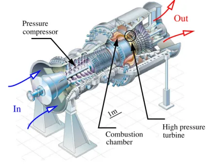
the higher is the turbine operation temperature, the greater is the potentially available efficiency. Nowadays, gas turbine efficiencies are around 40% in single-cycle and 60% in combined-cycle (SIEMENS) but the mechanical strength of the turbine components limits the temperature increase. The quest for higher temperatures is dominated by materials and process developments. 1 compressor Pressure
In
Out
chamberCombustion High pressureturbine
1m
Figure I.1 : Schematic showing a land based gas turbine with a capacity of 287 Megawatts (SIEMENS).
I.1. HISTORICAL OVERVIEW 3
I.1
Historical overview
Requiring high performance at elevated temperatures, superalloy turbine blades were been developed in the earlier 1950’s. The cooling system of turbine blades in the 1960’s and the alloy microstructure improvements (directional solidification and single-crystal) have significantly contributed to increase upper service temperatures. Associated to thermo-insulator coatings, the objectives were to protect the superalloy substrate of high temperatures and the hurtful consequences. Ceramic protective coatings for turbine applications have been considered since the late 1940’s (Harrison et al., 1947, Garrett and Gyornak, 1953). Thermal barrier coatings (TBCs) are typically formed of ceramic materials deposited by air plasma spraying (APS), flame spraying or physical vapor deposition (PVD) techniques. APS-TBCs are produced with a plasma spray gun, where the powder is injected into a plasma gas which is melt rapidly. This method is one of the lowest cost alternatives but yields low strain-tolerant microstructures. In the hottest areas of gas turbine engines, TBCs are more often deposited by electron beam-physical vapor deposition (EB-PVD), which yields a strain-tolerant columnar grain structure (see Fig. I.2) which limit the magnitude if the stress responsible for TBC spallation.
I.2
Composition, morphology and properties of TBC systems
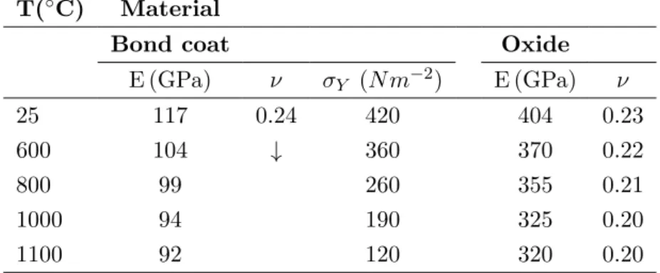
The two main functions of TBC systems consist of (i) lowering the temperature and (ii) protecting the Ni-based superalloy substrate from detrimental oxidation. The requirement to lower the substrate temperature has been justified previously. The in-service conditions also mean severe oxidation. TBCs should protect the superalloy substrate to severe environmental conditions which can modify its chemical composition and impaired its mechanical properties. Thermal barrier coating systems are composed of three constituents, as shown in Fig. I.2. The top coat (TC) provides thermal insulation to the substrate. This low-thermal conductivity layer consists of a ceramic which is deposited onto a bond coat. It is almost transparent to oxygen and does not therefore provide any oxidation resistance. The bond coat (BC) has two functionalities: firstly, it ensures a good adherence between the substrate and the thermally insulating layer (ceramic) and secondly, it preserves the substrate chemical composition. Indeed, the bond coat constitutes a reservoir of aluminium reacting with the oxygen allowing the formation of a protective alumina layer at the bond coat-ceramic interface, the so-called thermally grown oxide (TGO).
I.2.1 Top coat insulator layer
Thermal barrier coatings comprise thermally insulating materials which have sufficient thickness and durability to sustain a large temperature gradient between the substrate and the top coat surface, around 80 to 150◦C. Few methods are used to deposit thermal insulators. In our case, the top coat consists of a 135 µm thick layer of yttria partially stabilised zirconia (YSZ), ZrO2-8%Y2O3 and in the case of an EB-PVD type exhibits a columnar microstructure
(Fig. I.2). This process allows to deposit a thin film of material on a substrate, according to the following sequence:
1. the deposited material is converted into vapor by physical means,
Hot gases
20µm
YSZ
Purposes: − lowering temperature Material: Yttria Stabilised Zirconia (YSZ)
Material: NiCoCrAlY
Purposes: − providing adherence Process: EB−PVD or HVOF
Superalloy
Process: Electron beam physical
Thermal insulating top coat layer
Oxidation resistance bond coat (BC)
vapor deposition (EB−PVD)
TGO
BC
Substrate: CMSX−4
− high in−plane compliance
− constituing an aluminium reservoir
1 2
Al3+
O2−
Figure I.2 : Scanning electron micrograph of the layered EB-PVD TBC system showing the three TBC components: the thermal insulator (YSZ), the thermally grown oxide (TGO) and the bond coat (BC) and their respectively functions to protect the superalloy substrate.
3. the vapor undergoes condensation on the substrate to form the columnar layer.
In this work, an EB-PVD YSZ coating has been selected for the following reasons: (i) its low thermal conductivity (2 W/m2K) with minimal temperature sensitivity, (ii) its relatively
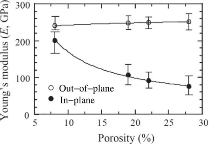
high coefficient of thermal expansion compared to many other ceramics, reducing the thermal expansion mismatch with the substrate, (iii) its good resistance to the entrainment of high velocity particles in the engine gases (erosion) (Mercer et al., 2005) and (iv) its high planar compliance due to the columnar microstructure. The in-plane direction is parallel to the macroscopic ceramic-bond coat interface and correspond to direction X1 in Fig. I.2.
I.2.2 Thermally grown oxide
The thermally grown oxide (TGO) is a chemical reaction product which forms at high temperatures in air due to the mechanism of outward and inward diffusion of the respective bond coat metal cations and oxygen anions, as illustrated in Fig. I.2. TGOs, such as alumina (α-Al2O3), act as protective oxides in oxidising environments and are used to protect
the substrate from detrimental oxidation. If the oxidation principle is well understood, the reality is more complex because numerous criteria are required to provide good protective properties to the oxide layer: to cover the substrate uniformly, to be strongly adherent to the bond coat, to consume as less as possible the bond coat, to be stable, to be resistant at several environment (stress, temperature...). Some of these criteria are difficult to control for a simple reason: mechanisms governing the bond coat oxidation are most of the time not
I.3. DAMAGE MECHANISMS IN TBC SYSTEMS 5
well understood. Nevertheless, the understanding of the bond coat oxidation is fundamental because damage can occur in this zone of TBC systems.
The initial TGO thickness is around 0.5 µm after the YSZ top coat deposition-process and increases with oxidation time. Even if the TGO layer thickness is greatly lower in comparison with the ceramic layer and bond coat, the oxide growth plays a major role in TBCs lifetime. This study takes particularly care on the thermo-mechanical phenomena which are or could be influenced by oxide growth. In the present multi-scale approach, the objective will be to model the complex time-evolution of the oxide layer properties: its morphology, thickness growth, associated growth strains and its mechanical and thermal properties.
I.2.3 Bond coat
Bond coats aim to provide (i) sufficient adhesion resistance between the top coat and the substrate and (ii) good oxidation resistance to TBC systems. Furthermore, other requirements of the bond coat are:
• to reduce oxide growth and to improve its interfaces toughness, furthermore the TGO microstructure depend on the bond coat chemical composition,
• to provide a strain compliance at high temperatures thanks to its high creep behaviour. This point will be investigated in Chapter III, in particular the creep and plastic bond coat behaviour influence on local stress and strain fields close to the TGO.
Two different types of bond coats are considered to be the best alternative composition regards their objectives: Pt-modified aluminide and N iCoCrAlY . The production process for overlay coatings based on N iCoCrAlY alloy system are EB-PVD, High Velocity Oxygen Fuel (HVOF), Vacuum Plasma Spraying (VPS) and Air Plasma Spraying (APS). In particular, HVOF and APS processes provide good compromise between performance, easy monitoring and processing cost. The deposition process and chemical composition of bond coats mainly influence their microstructures and properties.
I.3
Damage mechanisms in TBC systems
In addition to provide low thermal conductivity and oxidation resistance, TBCs used on gas turbine components are required to withstand damage. For turbine manufacturers, damage leads to the partial lost of thermal insulating properties. Several damage mechanisms can occur simultaneously, such as erosion due to foreign particles, infiltration of atmosphere particles and spallation of the ceramic layer.
I.3.1 Erosion: impact damage
Damage generated by the entrainment of high velocity particles through the gas engine can be in the form of erosive wear (generally cause by smaller particles, lower particle velocities, and/or lower impingement angles), see Fig. I.3(a), and impact spallation (generally caused by larger particles with greater particle velocities, and/or greater impingement angles), see Fig. I.3(b). As a consequence, the thickness of the top coat decreases and thermal insulation is not longer assured (Evans et al., 2006). A solution is to process a coating with an outer portion covering the initial ceramic layer so as to enhance impact resistance.
Molten deposits
Impact damage
Erosion Impact CMAS BC TGO a) b) c)Figure I.3 : Illustration of damage mechanisms that can occur in TBCs due to foreign objects: (a) erosion by small particles, (b) impact of large particles and (c) CMAS infiltration (Evans et al., 2008).
I.3.2 Molten deposits: calcium-magnesium-alumino-silicate infiltration
Calcium-magnesium-alumino-silicate (CMAS) are common particles that are ingested into turbines and can form a molten layer at high temperatures. For engines operating in sandy environments, it has been observed that CMAS rapidly penetrate the open structure of the EB-PVD YSZ coating as soon as melting occurs (Mercer et al., 2005, Chen, 2006, Kraemer et al., 2008). There are many implications: (i) a decrease of the top coat strain compliance at low temperatures, (ii) an increase of the thermal conductivity and then higher local bond coat temperatures that can accelerate the oxide growth and (iii) a modification of the chemical composition of the YSZ ceramic layer. CMAS induce horizontal cracks in the top coat, as illustrated in Fig. I.3(c) (Evans and Hutchinson, 2007).
I.3.3 Top coat spallation
Observations made on engine components removed from service have indicated that, when TBC systems are subjected to critical thermal histories, the coatings are susceptible to spalling. TBCs exhibit multiple failure mechanisms which depend on their multiple structures (APS or EB-PVD top coats, N iCoCrAlY or (P t, N i)Al bond coats) or on the thermal loads. Most of the time, damage initiates close to the TGO layer, and when damage at one of the TGO interfaces or in the TGO itself become large enough, delamination is triggered leading to spallation. Figure I.4 illustrates a particular TBCs spallation mechanism, by buckling of the top coat due to interfacial damage at the TGO-BC interface. The top coat spallation is driven by the stored elastic strain energy per unit area (linked to the high level of compressive in-plane stress) in the top coat and oxide layer.
Two conditions have to be fulfilled to induce the top coat spallation: (i) micro-damage should be present at the future delaminated interface and (ii) the stored elastic strain energy per unit area has to reach the interface toughness. The stored energy is relaxed during top coat spallation. The interface toughness decreases with thermal exposure time because interfacial damage extension can proceed either by ductile void growth
I.3. DAMAGE MECHANISMS IN TBC SYSTEMS 7
(Dalgleish et al., 1989) or by microcrack growth induced by normal traction at the oxide interface (Reimanis et al., 1990, Reimanis et al., 1991). A major difficulty in a TBC study is that, interfacial damage and spallation mechanism are specific to each TBC system and the lifetime prediction should be adapted to the specific failure mechanism of the system to be predictive. Another difficulty is to bring together the numerous phenomena influencing the TBC lifetime which most of the time is controlled by events happening at different scales.
II Interfacial damage III Buckling−delamination BC BC YSZ TGO YSZ YSZ BC BC TGO YSZ Damaged interface I As−deposited IV Spallation
Figure I.4 : Schematics showing one of the TBC system spallation mechanism: (I) safe TBC system, (II) TGO interfacial damage, (III) buckling-delamination and (IV): top coat spallation.
I.4
Outline of thesis
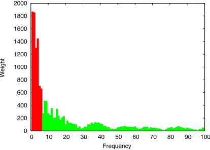
Lifetime assessment of TBC systems requires a preliminary work based on the knowledge of the morphology and microstructure time-evolution of each constituent of the TBC system. The thesis is structured as follows: the Chapter II describes the investigation of (i) the typical microstructure of the porous columnar top coat ceramic, processed by EB-PVD using image-processing tools, (ii) the bond coat multiphase microstructure and (iii) the thin thermally grown oxide which develops at the bond coat-ceramic interface during high temperatures exposure. Based on previous observations and literature data, appropriate models to describe each individual material property of the TBC constituents are proposed. Finally, time-evolution of both oxide interface morphology is studied using image-processing and Fourier analysis. A representative elementary profile of the TGO layer is identified and a simulation of this profile is performed.
Motivated by the conclusions of the previous chapter, simulation and analysis of stress/strain fields occurring in EB-PVD TBC systems and their relationship with the observed macroscopic and microscopic damage are addressed in Chapter II. To reach this goal, the methodology to model oxide growth and to determine stress fields close to the moving TGO interface are presented. A parametric study dealing with the influence of the parameters characterising (i) the mechanical behaviour of each TBC constituent, (ii) the TGO morphology and (iii) the thermal loading on stress and strain fields is presented. Due to the main influence of the oxide roughness on the local stress fields close to the TGO, a realistic and complex simulation of the TGO morphology is performed using Fourier analysis. Stress and strain fields predicted with this latter approach and with a 3D sinusoidal simulation of the TGO profile will be compared to a simple 2D sinusoidal simulation of the TGO morphology. Chapter IV constitutes the keystone of this thesis as it examines the failure mechanisms of the studied TBC. To achieve this aim, samples tested under isothermal loading conditions are analysed and observed follow by discussions of the dominant EB-PVD TBC failure mechanisms. A distinction is made between macroscopic top coat spallation mechanisms and microscopic oxide interfacial damage. This latter is assumed to be responsible for the TGO-BC interface toughness decrease.
Finally, in Chapter V, motivated by the TBC microstructure analysis, identification of failure mechanisms and numerical simulation of the local stress/strain fields close to the oxide, a relevant multi-scale predictive model of the EB-PVD TBC system lifetime is proposed. This model is based on an energetic approach taking into account the combined effects of time-evolution of the stored elastic strain energy per unit area (due to high level of in-plane stress) and the TGO-BC interface toughness evolution. Oxide interfacial damage, responsible for the oxide interface toughness decrease will be defined as a function of the stress/strain fields close to the oxide interfaces using a model previously developed by Lemaitre (1992). The lifetime model parameters will be calibrated using literature data and validated by the experimental database presented in Chapter IV.
I.4. OUTLINE OF THESIS 9
References
Chen, X. (2006). CMAS delamination mechanisms in EB-PVD TBCs. Surface and Coating Technology, 200:3418–3427.
Dalgleish, B., Trumble, K., and Evans, A. (1989). The strength and fracture of alumina bonded with aluminium alloys. Acta Materialia, 37:1923–1931.
Evans, A., Clarke, D., and Levi, C. (2008). The influence of oxides on the performance of advanced gas turbines. Journal of European Ceramic Society, 28:1405–1419.
Evans, A., Fleck, N., Faulhaber, S., Vermaak, N., Maloney, M., and Darolia, R. (2006). Scaling laws governing the erosion and impact resistance of thermal barrier coatings. WEAR, 260:886–894.
Evans, A. and Hutchinson, J. (2007). The mechanisms of coatings delamination in thermal gradients. Surface and Coating Technology, 201:7905–7916.
Garrett, F. and Gyornak, C. (1953). NACA, RM-E 53 A:19.
Harrison, W., Moore, D., and Richmond, J. (1947). NACA, TN-1186.
Kraemer, S., Yang, J., and Levi, C. (2008). Infiltration-inhibiting reaction of gadolinium zirconate thermal barrier coatings with CMAS melts. Journal of American Ceramic Society, 91:576–583.
Mercer, C., Faulhaber, S., Evans, A., and Dariola, R. (2005). A delamination mechanism for barrier coatings subject to calcium-magnesium-alumino-silicate (CMAS) infiltration. Acta Materialia, 53:1029–1039.
Reimanis, I., Dalgleish, B., Brahy, M., R¨uhle, M., and Evans, A. (1990). Effects of plasticity on the crack-propagation resistance of metal-ceramic. Acta Metallurgica Materialia, 38:2645–2652.
Reimanis, I., Dalgleish, B., and Evans, A. (1991). The fracture-resistance of a model metal/ceramic interface. Acta Metallurgica Materialia, 39:3133–3141.
Chapter
-II-EB-PVD TBC system
characterisation
Contents
II.1 Introduction . . . 12
II.2 Characterisation of the TBC constituents microstructure . . . 13
II.2.1 EB-PVD YSZ top coating . . . 13
II.2.2 Thermally grown oxide . . . 19
II.2.3 Bond coat . . . 28
II.3 Mechanical and thermal behaviour model of TBC constituents . 31
II.3.1 EB-PVD YSZ top coating . . . 31
II.3.2 Thermally grown oxide . . . 35
II.3.3 Bond coat . . . 37
II.4 Simulation of the TGO morphology . . . 40
II.4.1 Oxide interface roughness . . . 40
II.4.2 Representative elementary length of the TBC system studied . . . 43
II.4.3 Model of a realistic TGO morphology . . . 43
II.1
Introduction
In a land based turbine engine, thermal barrier coating systems covering the blades are submitted to severe conditions in terms of temperature gradients and mechanical loading. According to experimental and in-service feedback data, thermo-mechanical loading affects the microstructure of TBC constituents and its interface morphologies (Evans et al., 2001). Due to the combined effect of high temperatures and stresses in turbine blades, several time-dependent phenomena can occur: (i) sintering of the porous ceramic top coat (Lu et al., 2001, Renteria and Saruhan, 2006), (ii) diffusion mechanisms through the bond coat and the superalloy substrate, modifying of the bond coat chemical composition and its microstructure (Nicholls, 2003, M¨uller and Neusch¨utz, 2003), (iii) the oxide thickness growth associated with the bond coat oxidation at the YSZ ceramic-bond coat interface, and (iv) evolution of the oxide morphology (Tolpygo and Clarke, 1998, Panat et al., 2003).
Lifetime assessment of TBC systems requires a preliminary work based on the knowledge of each individual constituent material properties and the interface morphology of the multilayer EB-PVD thermal barrier coating system. This chapter investigates:
• the time-evolution of EB-PVD TBC morphology and the parameters defining the microstructure,
• the relationship between microstructure and mechanical/thermal behaviour, • constitutive material model of each individual TBC constituent.
In Section II.2, time-dependent phenomena occurring in each TBC constituent and their consequences on the microstructure evolution is investigated. Firstly, the typical microstructure of the porous columnar ceramic, processed by EB-PVD, and its evolution due to sintering is presented. In particular, intercolumnar porosity, characterising the YSZ microstructure is analysed using image-processing tools. Secondly, investigations of the bond coat microstructure are focused on the development of different multiphase layers in the bond coat due to interdiffusion with the substrate. The thin thermally grown oxide (TGO) layer is also studied, in particular its (i) kinetic oxide growth, (ii) phase composition, (iii) microstructure and (iv) growth strains associated with the bond coat oxidation. In Section II.3, the constitutive material model of each TBC constituent, at different scales is proposed. Based on previous observations and literature data, these models take into account the effects of extended thermal exposure on the mechanical behaviour. Finally, in Section II.4, the TGO morphology is studied using image-processing analysis. The time-evolution of the TGO interfaces roughness is also quantified. At the same time, a representative elementary profile of the oxide morphology is identified and a model of this profile is developed based on Fourier analyses. These studies are preliminary steps for the models of the TGO morphology proposed in Chapter III.
II.2. CHARACTERISATION OF THE TBC CONSTITUENTS MICROSTRUCTURE 13
II.2
Characterisation of the TBC constituents microstructure
II.2.1 EB-PVD YSZ top coating
Ceramic coatings are used to protect hot constituents from the combustion gases. Their deposition is done using EB-PVD technology which requires complex and expensive equipments but provides superior coatings properties than those resulting from other processes, such as APS or HVOF (Beele et al., 1999). The main enhancement consists of its strain-tolerance, improved due to its typical columnar microstructure (An et al., 1999). Mechanical properties, as well as thermal conductivity depend on the texture and microstructure of the top coat (Zhua et al., 2001). The most critical feature is porosity for an EB-PVD YSZ top coating. A relevant model of such microstructure behaviour should be based on macro and microscopic description of the porous ceramic. The influence of thermal exposure times on the porosity spatial distribution along the ceramic layer, and more generally the sintering effects on the ceramic microstructure, are investigated in this section.
II.2.1.1 Observations and descriptions of the microstructure
Yttria stabilised zirconia (YSZ) top coat produced by EB-PVD contains individual columns which grow in a preferred crystallographic direction by adding molecules from the vapor phase (Schulz and Schm¨ucker, 2000, Kato et al., 2005, Jang and Matsubara, 2006). SEM micrographs shown in Figure II.1 illustrate a typical columnar microstructure of the YSZ EB-PVD top coat after heat treatment (isothermal test during 13,500 h at 870◦C). The top coating morphology exhibits elongated intercolumnar pores that become predominantly aligned perpendicular to the plane of the coating as its thickness increases, see Fig. II.1(a). The elongated intercolumnar porosity, noted ρe, increases the coating compliance, and leads
to an improved lifetime of the TBC. Nevertheless, close to the TGO, the ceramic does not exhibit the typical vertical columnar microstructure seen elsewhere, inducing a low strain tolerance in comparison with the ceramic top part, see Fig. II.2(a).
A finer distribution of intracolumnar pores present inside the column also exists (Lughi et al., 2004). These nanopores, whose size is under 100 nm, constitute the internal porosity, ρi, as shown in Figs. II.1(b) and (c). Thermal conductivity is governed by the
spatial distribution, the size and the morphologies of these nanopores (Jung et al., 2003). At a lower scale, texture of YSZ top coat consists of non-transformable metastable tetragonal θ’ phase (Schulz et al., 1996). It could evolve at high temperatures (Lughi and Clarke, 2005) but these nano-scale considerations are not taken into account in our approach because they are difficult to model and are not adapted to the scale of the present study.
II.2.1.2 Sintering of the YSZ EB-PVD top coat
Sintering occurs in the YSZ ceramic after long exposure times at high temperatures, which is typical of land based gas turbine. The EB-PVD YSZ columns develop pronounced smoothing of their surfaces and coalesce together (Lu et al., 2001, Renteria and Saruhan, 2006). As shown in Figure II.1(c), bridges or necks form between columns. As a consequence, the strain compliance of the top coat decreases and driving spallation in-plane stresses increase. The densification of the columns themselves could also occur after long exposure times which increases the intrinsic Young’s modulus of the columns. The surface column smoothing is one of the observed consequences of the intracolumnar pores distribution and
size time-evolution (Leyens et al., 1999, Lu et al., 2001). Sintering affects the mechanical and conductivity properties and should be taken into consideration in a lifetime predictive model (Azzopardi et al., 2004, Renteria et al., 2006, Ratzer-Scheibe and Schulz, 2007).
20µm 5µm 1µm Intercolumnar Intracolumnar Intracolumnar porosity a) b) c) Bridges porosity porosity
Figure II.1 : SEM micrographs showing the porous morphology of an EB-PVD YSZ coating at different scales, after 13,500 h at 870◦C: (a) columnar microstructure and intercolumnar pores, ρe, (b) intracolumnar pores, ρi, and (c) bridges occurring between columns due to
sintering.
II.2.1.3 External porosity evaluation along the top coat by image-processing analysis
The objective of this part of the work is to characterise the YSZ ceramic microstructure and in particular the intercolumnar porosity. The spatial distribution of the external porosity ρe
along the YSZ layer is investigated for different time-temperature thermal histories. SEM micrographs have been obtained from samples tested under isothermal loading at different temperatures ranging from 930 to 1050◦C and exposure times from 0 to 1000 h. The methodology to quantify external porosity is presented and the results for the different samples are analysed.
II.2. CHARACTERISATION OF THE TBC CONSTITUENTS MICROSTRUCTURE 15
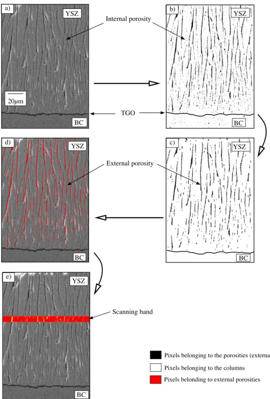
a) Methodology
The first step of this method consists of extracting the external porosity from SEM micrographs. We assume that pixels with weak luminance in the ceramic layer can be regarded as pores. The initial picture of the SEM micrograph of Fig. II.2(a) is encoded by pixels which are characterised by a grey level value ranging from 0 (dark) to 255 (white) (8 bits format). To extract black pixels corresponding to pores, a binary picture of the initial SEM micrograph is required and is obtained by the following procedure: all the pixels of the initial micrograph whose grey values range from 0 to 10 are amended as black pixels. The other pixels became white. The binary picture of the initial micrograph is given in Fig. II.2(b). This first step requires the use of equivalent grey level histogram for each SEM micrograph. This condition can be respected during the SEM micrograph capture. Note that in addition to the black pixels corresponding to the external pore, black pixels belonging to the internal porosity inside the columns themselves are also extracted. A special numerical tool is used to identify only the external porosity, see Fig. II.2(c). To that purpose, all the isolated porosities whose size were under 100 nm have been considered to be internal porosities and not retained.
The second step of the procedure to analyse the top coat morphology consists of the external porosity evaluation of the ceramic layer. The image-processing relies on the scanning procedure as shown in Figs. II.2(d) and (e). A 4 µm-width scanning band moves along the YSZ layer. For each position of this band, a mean value of the external porosity is obtained. The intercolumnar porosity is represented as a fraction of the whole image area. The influence of the scanning band width has been evaluated. A 4 µm-width band provides an adequate ratio between precision and processing time.
b) Results
The evaluation spatial distribution of intercolumnar porosity from the bottom to the top of the YSZ ceramic layer is discussed here. The measurements for different samples tested under different exposure times and temperatures are given in Figs. II.3 (930◦C) and II.4 (990◦C). Before any thermal exposure (0 h), the external porosity ranges from a low value (2%) close to the oxide layer, to a maximal value close to the top of the ceramic layer. The low porosity close to the TGO layer indicates that the ceramic is rather compact there. This result is consistent with the preliminary observations of EB-PVD micrographs, see Fig. II.2(a). Due to the EB-PVD process, a few microns are necessary to generate vertical columns and since columns are forming, external porosity is very low. Close to the oxide layer, the external porosity is similar for all the samples, see Figs. II.3 and II.4.
Close to the top of the ceramic layer, the external porosity is quasi-constant and depends on the time-temperature thermal loading, as expected. On the top surface of EB-PVD YSZ ceramic, the external porosity decreases with increasing exposure times and temperatures. At 930◦C, ρe is equal to 16%, 14% and 10.4% after 120 h, 300 h and 1000 h, respectively. At
990◦C, for the same thermal exposure times, the values of ρe are 13.5%, 12.4% and 10.5%.
These values should be compared to the initial external porosity on the top surface of the YSZ layer before any thermal exposure, namely 16.6%. These measurements agree with those reported at the top of the ceramic layer before and after 24 h of exposure at 1500◦C, namely 12% and 9%, respectively, (Wellman and Nicholls, 2005).
Figure II.5 shows the temperature influence on the spatial porosity distribution along the ceramic layer after 300 h at 930◦C, 990◦C and 1050◦C. It can be seen that sintering is responsible for a sharp decrease of the external porosity at 1050◦C. At this temperature, the porosity increases linearly through the ceramic layer thickness. Due to the complete
Pixels belonging to the porosities (external and internal) Pixels belonging to the columns
Pixels belonding to external porosities Internal porosity External porosity Scanning band TGO a) YSZ 20µm YSZ b) BC BC YSZ e) d) YSZ YSZ BC BC BC c)
Figure II.2 : (a) Initial SEM micrograph of the EB-PVD TBC cross section, (b) binary picture with external and internal porosities, (c) binary picture showing only the extracted external porosity, (d) external porosity reported in the initial SEM micrograph and (e) evaluation of the external porosity percentage along a 4 µm-wide scanning band.
spallation of specimens tested after 300 h at 1050◦C, it was not possible to obtain similar measurements for times up to 300 h.
II.2. CHARACTERISATION OF THE TBC CONSTITUENTS MICROSTRUCTURE 17 0 2 4 6 8 10 12 14 16 18 0 20 40 60 80 100 120 External porosity (%)
Distance from the oxide layer ( m)
TGO−YSZ interface YSZ top surface
1000 h 300 h 120 h 0 h 930°C µ
Figure II.3 : Percentage of external porosity along a 4 µm-wide scanning band, as a function of the distance from the oxide layer after 0 h, 120 h, 300 h and 1000 h exposure 930◦C.
0 2 4 6 8 10 12 14 16 18 0 20 40 60 80 100 120 External porosity (%)
Distance from the oxide layer ( m)
990°C µ 1000 h 300 h 120 h 0 h
TGO−YSZ interface YSZ top surface
Figure II.4 : Percentage of external porosity along a 4 µm-wide scanning band, as a function of the distance from the oxide layer after 0 h, 120 h, 300 h and 1000 h exposure at 990◦C.
0 2 4 6 8 10 12 14 16 0 20 40 60 80 100 120 External porosity (%)
Distance from the oxide layer ( m)
TGO−YSZ interface YSZ top surface
300 h
1050°C 930°C
990°C
µ
Figure II.5 : Percentage of external porosity along a 4 µm-wide scanning band, as a function of the distance from the oxide layer after 300 h at 930◦C, 990◦C and 1050◦C exposure time.
II.2.1.4 Discussions
The present investigation has provided quantitative and qualitative information about the evolution of top coat EB-PVD microstructure at different temperatures and exposure times. SEM micrographs observation and analysis of the external porosity spatial distribution have shown that: (i) high temperatures typical of industrial practice induces changes in the microstructure (sintering effects) and (ii) intercolumnar porosity varies strongly through the ceramic layer. The external porosity spatial distribution also depends on the deposition process (Terry et al., 1999, Jang and Matsubara, 2004). According to Jang and Matsubara (2004), the total external porosity (pores whose size > 100 nm) increases with the substrate rotation speed and ranges from 5 to 18% for 0 to 20 rpm, respectively. Our approach provides an improvement in the quantification of the external porosity spatial distribution through the top coat and provides more available information than the mean external porosity measured on the top surface of the ceramic layer (Wellman and Nicholls, 2005).
If the need to model the sintering effect on the YSZ top coat morphology is clear from the high level of porosity in a major part of the layer, it might not be required in the region close to the TGO where intercolumnar porosity is lower. Likewise, the columnar microstructure of the ceramic is inhomogeneous across the YSZ top coat thickness. Accordingly, the model to be proposed to describe the top coat mechanical behaviour will not be the same for the ceramic part close to the TGO as for the rest of the YSZ layer. The internal porosity spatial distribution has been also investigated. Nevertheless, the image-processing analysis does not provide interesting results, principally because the criterion to characterise a nano-porosity (<100 nm) required a high level of resolution of SEM micrographs.
II.2. CHARACTERISATION OF THE TBC CONSTITUENTS MICROSTRUCTURE 19
II.2.2 Thermally grown oxide
As previously discussed, the thin oxide layer which develops at the bond coat-ceramic interface, provides good oxidation resistance to TBC systems. Despite the thin nature of the TGO in comparison to the bond coat and YSZ ceramic layer, it plays a crucial role in the lifetime of TBC systems. Actually, damage develops close to the TGO and is responsible for a decrease of the interface toughness (Vasinonta and Beuth, 2001, Guo et al., 2005). Furthermore, the oxide thickness growth increases the stored elastic strain energy per unit area which is responsible for TBC spallation.
Mechanisms occurring during alumina growth are more complex than for other oxides (Levi et al., 1986, Monceau et al., 2000, Chevalier, 2007) and have to be described specifically. The objective of this section is to characterise the following TGO properties: (i) oxide thickness evolution (oxidation kinetics), (ii) chemical composition, (iii) microstructure and (iv) growth strains associated with the bond coat oxidation. The oxide morphology and its corresponding roughness will be presented in detail in the next section (II.4).
II.2.2.1 TGO growth: oxidation kinetics
Oxide growth kinetics have been determined at 950◦C, 1050◦C and 1150◦C, for times up to
1000 h by the University of Birmingham (Taylor et al., 2006) for TBC systems provided by SIEMENS. The measured oxide thickness evolution is shown in Fig. II.6. TGO thickness measurements were made in a cross section normal to the bond coat-YSZ ceramic interface. Only the specimens with no damage close to the oxide have been analysed. Kinetics equation that describes the mean TGO is:
hox= h0+ (knt)
1
n, (II.1)
where h0 is the oxide thickness of the as-received specimen, t is the oxidation time and kn
and n are material parameters which depend on temperature. These data are required for the numerical approach to be presented in Chapter III.
0 1 2 3 4 5 6 7 8 9 10 11 0 200 400 600 800 1000 Oxide thickness ( m) Oxidation time (h) 950°C 1050°C 1150°C µ
Figure II.6 : Oxide thickness time-evolution for a N iCoCrAlY bond coat at three different temperatures: 950◦C, 1050◦C and 1150◦C (Taylor et al., 2006).
II.2.2.2 Investigation of the TGO chemical composition
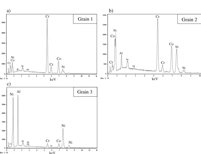
The purpose of this section is to carry out a detailed assessment of the chemical composition of the TGO phases. An appreciation of the TGO chemistry will be of assistance to (i) the overall understanding of TGO evolution during thermal exposure and (ii) to model its mechanical behaviour. In order to analyse the TGO metallographic composition, a cross section of a specimen, exposed at 870◦C during 13,500 h, was examined by Scanning Electron Microscopy (SEM) and Energy-Dispersive Spectroscopy (EDS) techniques.
TGO Zone 1:Pure−alumina
Zone 2: Y−pegs Zone 3: particles 1µm Bond coat BC YSZ
3
1
2
Figure II.7 : SEM micrograph of the TGO layer, showing (1) α-alumina phase, (2) Y-pegs and (3) bond coat particles trapped within the oxide.
a) Observations
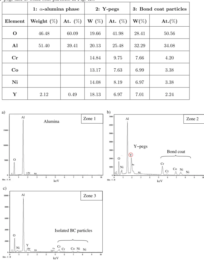
Cross-section observations of the TGO revealed an inhomogeneous composition. In Figure II.7, three different areas can be distinguished:
Zone 1: this is the principal zone of the oxide. Its composition is shown in Fig. II.8(a) and Table II.1. EDS revealed that the grains within the regular TGO region are composed of almost pure Al2O3 phase, as expected.
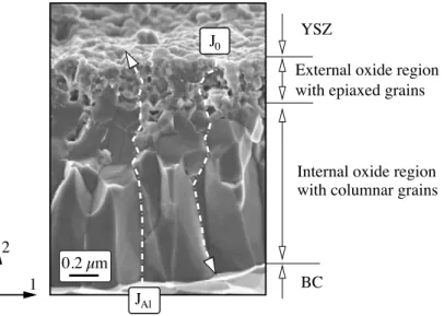
Zone 2: many pegs have been observed in the TGO and more precisely at the TGO-BC interface. The pegs thicknesses typically range from 5 to 8 µm, whereas the average TGO thickness is around 3 µm. There is no visible porosity within the pegs themselves. The qualitative and quantitative composition of this pegs are, respectively, given in Fig. II.8(b) and Table II.1.
Zone 3: according to the EDS spectrum, Fig. II.8(c) and Table II.1, this region corresponds to the elements of the bond coat trapped within the TGO.
b) Discussions
The thermally grown oxide in the studied TBC system presents a complex morphology and microstructure. It consists primarily of three constituents: (1) α-alumina, (2) a distribution of oxide pegs rich in yttrium and (3) N iCoCrAlY bond coat particles trapped within the TGO. The formation of these Y-rich particles is likely to be due to one of two mechanisms.
II.2. CHARACTERISATION OF THE TBC CONSTITUENTS MICROSTRUCTURE 21
Table II.1 : Quantitative results of the chemical composition for 1: α-alumina phase, 2: Y-pegs and 3: bond coat particles in Fig. II.7
1: α-alumina phase 2: Y-pegs 3: Bond coat particles
Element Weight (%) At. (%) W (%) At. (%) W(%) At.(%)
O 46.48 60.09 19.66 41.98 28.41 50.56 Al 51.40 39.41 20.13 25.48 32.29 34.08 Cr 14.84 9.75 7.66 4.20 Co 13.17 7.63 6.99 3.38 Ni 14.08 8.19 6.97 3.38 Y 2.12 0.49 18.13 6.97 7.01 2.24 Zone 2 b) Zone 1 Alumina a) Zone 3 c) Isolated BC particles Bond coat Y−pegs O keV O Ni Ni Ni Cr Cr Co Al Y keV keV Cr Cr Co Ni Ni Al Y O Ni Al
Figure II.8 : EDS spectrum from the zone (a) 1 α-alumina, (b) 2 Y-rich oxide pegs and (c) 3 trapped bond coat particles.