Open Archive TOULOUSE Archive Ouverte (OATAO)
OATAO is an open access repository that collects the work of Toulouse researchers and
makes it freely available over the web where possible.
This is an author-deposited version published in:
http://oatao.univ-toulouse.fr/
Eprints ID: 19656
To link to this article: DOI:10.1016/j.compositesa.2017.11.022
URL:
http://dx.doi.org/10.1016/j.compositesa.2017.11.022
To cite this version:
Trinh, Pham Van and Luan, Nguyen Van and
Phuong, Doan Dinh and Minh, Phan Ngoc and Weibel, Alicia and
Mesguich, Davidand Laurent, Christophe Microstructure,
microhardness and thermal expansion of CNT/Al composites
prepared by flake powder metallurgy. (2018) Composites Part A:
Applied Science and Manufacturing, vol. 105. pp. 126-137. ISSN
1359-835X
Any correspondence concerning this service should be sent to the repository
administrator:
[email protected]
Microstructure, microhardness and thermal expansion of CNT/Al
composites prepared by flake powder metallurgy
Pham Van Trinh
a,b, Nguyen Van Luan
a, Doan Dinh Phuong
a,c, Phan Ngoc Minh
a,c, Alicia Weibel
b,
David Mesguich
b, Christophe Laurent
b,⇑aInstitute of Materials Science, Vietnam Academy of Science and Technology, 18 Hoang Quoc Viet Str., Cau Giay Distr., Hanoi, Viet Nam bCIRIMAT, Université de Toulouse, CNRS, INPT, UPS, 118 route de Narbonne, 31062 Toulouse Cedex 9, France
cGraduate University of Science and Technology, Vietnam Academy of Science and Technology, 18 Hoang Quoc Viet Str., Cau Giay Distr., Hanoi, Viet Nam
Keywords: A. Carbon nanotubes A. Metal matrix composite B. Thermal properties E. Powder processing
a b s t r a c t
Carbon nanotube/aluminum (CNT/Al) composites are prepared by a combination of flake powder metal-lurgy and hot-isostatic-pressing. The specimens are investigated by several techniques including Raman spectroscopy, optical microscopy, scanning- and transmission electron microscopy. The composites show a layered-microstructure with a stacking of CNT/Al flakes with a CNT-rich layer between two flakes. The individual Al grains forming the flakes are about 500 nm in size. The CNTs are well dispersed within a flake and they bridge the micro-cracks. The results reveal that the coefficient of thermal expansion (CTE) decreases markedly upon the increase in carbon content, reaching 15.4 ! 10"6K"1for the specimen
with a carbon content of 2.0 wt% (2.9 vol%), i.e. a 30% decrease compared to the CTE of pure Al. This could arise from the layered-microstructure resulting from the utilization of Al flakes as opposed to rounded particles.
1. Introduction
Silicon, the material at the basis of the semiconductor devices,
shows a low coefficient of thermal expansion (CTE) (5 ! 10"6
K"1) in comparison with the common packaging materials like
copper (17 ! 10"6K"1) and aluminum (21–26 ! 10"6K"1) [1,2].
The CTE difference will cause distortions at the interface upon repeated changes in temperature, which ultimately will lead to failure of the device. Aluminum-matrix composites with a lower CTE than pure Al have been prepared by adding some low CTE
materials such as Si, SiC, AlN and diamond[2,3]. Carbon nanotubes
(CNTs) have been become an attractive additive material for
reduc-ing the CTE of the aluminum-matrix composites[4–13]because of
a very low or even negative CTE, in the range "2 ! 10"5–0.5 !
10"5K"1 depending on the CNT characteristics [14]. The end
results however depend on many materials- or process-parameters, including the precise nature of the matrix (pure or alloyed Al), of its grain size (nano-, micrometric), of the carbon content and of the kind of CNTs (single-wall, double-walled, multi-walled) and of the consolidation route (hot-pressing, hot
extrusion. . .) and atmosphere (vacuum, N2, Ar) (Table 1). CTE as
low as 10 ! 10"6K"1 have been reported when using
nanometric-sized Al with either single-wall CNTs [7] or
multi-walled CNTs (MWCNTs)[12]. Many techniques have been
devel-oped to prepare CNT/Al composite powders with a uniform
disper-sion of the CNTs[4,5,13,15,16]. However, high-energy ball-milling
[13] tends to damage the CNTs whereas molecular-level mixing
[15] and in situ synthesis of CNTs in metallic powders[16]may
lead to oxide impurities. Besides these techniques, the so-called polyester binder-assisted (PBA) mixing technique has been reported for dispersing CNTs in a metallic powder, without damag-ing them, with the support of polyesters such as polyvinyl alcohol
(PVA), natural rubber and ethylene glycol [17–23]. Moreover, it
seems that using Al in the form of flakes, as opposed to isotropic grains, to prepare CNT/Al composites, is beneficial, at least to increase tensile strength without losing too much plasticity
[19,20,24–26]. The aim of this study is to investigate the CTE of MWCNT/Al composites prepared by a combination of flake powder metallurgy, PBA mixing technique and hot-isostatic-pressing. 2. Experimental
2.1. Composite preparation
A commercial Al powder (Hunan Jinhao Aluminum Industrial
Co., Ltd., 99.5%, average diameter 24
l
m) was selected for thehttps://doi.org/10.1016/j.compositesa.2017.11.022
⇑Corresponding author at: CIRIMAT/Université Paul-Sabatier, 118 route de Narbonne, 31062 Toulouse Cedex 9, France.
study. Commercial carboxyl-functionalized MWCNTs (Chengdu Organic Chemicals Co. Ltd.) were used. The details of the function-alization process are not known to the authors. The carbon content in the MWCNT specimen is equal to 95 wt%, the balance probably corresponding to some residual metal catalysts. The key character-istics of the MWCNTs (number of walls, outer and inner diameters, length and presence of defects) are determined later in the paper.
MWCNT/Al composite powders with a carbon content (Cn) equal to
0, 0.5, 1, 1.5 and 2 wt% were prepared by a PBA mixing route. They will be noted as P0, P0.5, P1, P1.5 and P2 hereafter. First, the Al powder was ball-milled (200 rpm, 2 h, ball-to-powder weight ratio
of 10:1, N2atmosphere). The so-obtained Al flakes were slowly
added to ethylene glycol under magnetic stirring (400 rpm, 2 h), forming the Al slurry. The appropriate amount of MWCNTs was
dispersed in ethanol as reported earlier [27,28] and the
so-obtained suspension was mixed with the Al slurry under magnetic stirring (400 rpm, 2–3 h) at 80 "C in order to evaporate ethanol. Finally, the resulting slurry was milled (150 rpm, 2 h,
ball-to-powder weight ratio of 10:1, N2 atmosphere) and heated at
220 "C for 24 h in vacuum (residual pressure 200 MPa) to remove ethylene glycol. The MWCNT/Al powders were consolidated by cold uniaxial compaction (200 MPa, 5 s) followed by capsule-free hot-isostatic-pressing (HIP, AIP6-30H, Isostatic Press Inc’s, US). The specimens were heated (10 "C/min) up to 620 "C, applying a 1 h dwell at this temperature for the pressing process (100 MPa).
A natural cooling down to room temperature was performed. The sintered specimens, in the form of pellets 10 mm in diameter and about 5 mm thick, were polished down to 1 mm using diamond slurries. The sintered specimens are noted S0, S0.5, S1, S1.5 and S2 hereafter.
2.2. Characterization
The MWCNTs were observed by high-resolution transmission electron microscopy (HRTEM, JEOL JEM 2100F operated at 200 kV). Their length was evaluated from field-emission-gun scanning electron microscopy images (FESEM, Hitachi S-4800 operated at 5 kV). The Raman spectra of the CNTs, powders and sintered speci-mens were recorded with a confocal RAMAN Microscope (Labram HR 800 Jobin Yvon) using 632 nm laser excitation. For each speci-men, the spectra were averaged from five areas. The pellet density was measured by Archimedes method. X-ray diffraction (XRD) pat-terns of powders and sintered specimens were recorded using a
Rigaku Rint Ultima diffractometer with Cu Ka radiation. The Al
grain size in sintered specimens was determined by optical micro-scopy (3D KEYENCE VHX-1000) on surfaces chemically etched by a
weak reagent (mixture of 0.25 mol L"1 KMnO
4 and 0.25 mol L"1
NaOH) at room temperature for 6 s. The Al powders and flakes as well as the sintered specimens were observed by FESEM (JEOL JSM 6700F operated at 5 kV and Hitachi S-4800 operated at 5
Table 1
Consolidation method, relative density (q± 1%), microhardness and CTEs of CNT/Al composites with different carbon contents (Cn, wt% or Cv, vol%).
Ref. Consolidation method Sample Cn(wt%) Cv(vol%) q(%) H (HV) CTE ( ! 10"6K"1)
[39] SPS Al 0 – – 45 – MWCNT/Al 0.5 – – 50 – [40] SPS MWCNT/Al 2 – 99 88 – [34] SPS MWCNT/Al 1 – – 44 – 3 – – 55 – 5 – 54.5 – [18] SPS + Hot extrusion MWCNT/Al 2 98 52 – [32,35] Vacuum sintering Al 0 – 34 – MWCNT/Al 0.75 – 50 [36] Hot-extrusion Al 0 99 39.4 – MWCNT/Al 2.5 99 84.5 – 5 99 95.2 – [37] Hot-extrusion MWCNT/Al 6 97 151 – [6] Hot-pressing Al 0 – – 26.1 MWCNT/Al 4 – – 23.2 SWCNT/Al 3 – – 20.4
[7] Vacuum sintering n-Al 0 – – 26.2
SWCNT/n-Al 10 – – 14.8 15 – – 9.8 [8] Hot-extrusion 2024 Al 0 – – 26.3 MWCNT/2024Al 1 22.5 [9] Hot-pressing 2009Al 0 – – 23.6 MWCNT/2009Al 1.5 – – 21.3 MWCNT/2009Al 4.5 – – 17.5
[11] Hot-pressing + Vacuum sintering MWCNT/2024Al 3 – – 19.2
MWCNT/2024Al 5 – – 17.9
[12] Sintering in N2 n-Al 0 – 90 – 80.1
MWCNT/n-Al 1 92 – 54.4
MWCNT/n-Al 3 94 – 10.5
MWCNT/n-Al 5 92 – 23.2
[13] Sintering in Air + Hot-extrusion Al 0 – 64 26.0
MWCNT/Al 1.5 – 81 24.8
MWCNT/Al 2.5 – 95 24.0
MWCNT/Al 3.5 – 115 22.5
MWCNT/Al 4.5 – 130 21.5
This work HIP S0 0 0 98 44 22.0
S0.5 0.5 0.7 96 55 19.5
S1 1.0 1.5 96 69 18.0
S1.5 1.5 2.2 95 83 16.4
kV). For the sintered specimens, a preliminary step of chemical
etching (mixture of 0.5 mol L"1 NaOH and 0.4 mol L"1 Na
2CO3,
30 s) was performed[27]. Indentation tests (50 g for 10 s in air at
room temperature) on polished surfaces were performed with a Vickers indenter (Shimadzu HMV 2000). The corresponding diago-nals of the indentation were measured using an optical microscope attached to the indenter. The calculated microhardness values are the average of five measurements. The CTE (DIL 402 PC dilatome-ter) was measured along the length of parallelepipedic specimens (6 mm ! 4 mm ! 5 mm). The measurements were performed from
50 to 250 "C (heating-rate 5 "C min"1).
3. Results and discussion 3.1. Microstructure
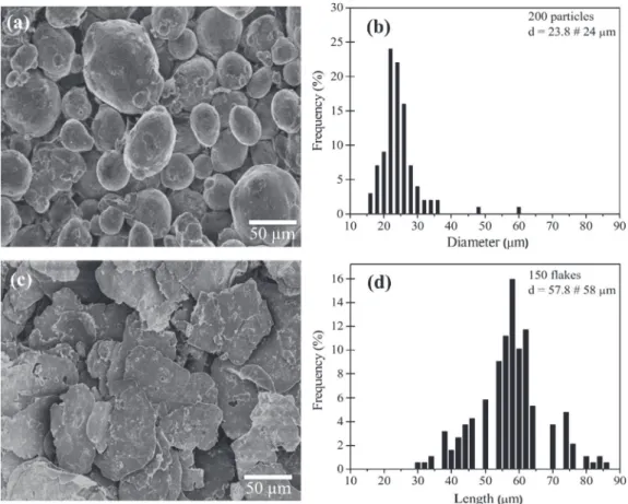
FESEM images of the as-received Al powder show that it is made up of rounded particles with an average size around 24 mm (Fig. 1a, b). The Al flakes obtained after ball-milling have an aver-age length equal to about 60 mm with a thickness of about 1.5 mm (Fig. 1c, d). FESEM images of the MWCNTs reveal that their
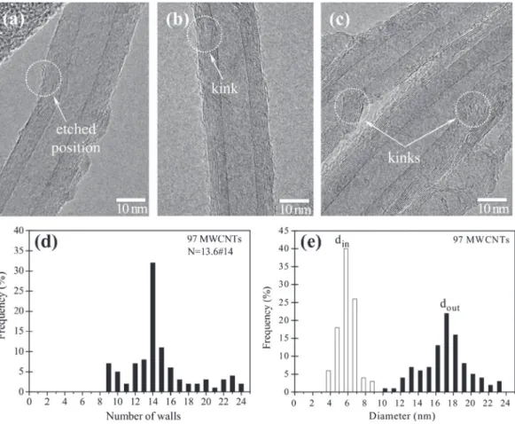
length is in the range 1–3 mm (Fig. 2). There are some structural
defects along the length, such as etched positions (Fig. 3a) and
Fig. 2. FESEM images of MWCNTs (a) as-received and (b) dispersed in water then dropletted on a Si substrate.
kinks (Fig. 3b, c), which are fairly typical of as-grown MWCNTs but could partly result from the functionalization process. The number
of walls (Fig. 3d) and the outer and inner diameters (Fig. 3e) were
measured for about 100 CNTs on HRTEM images. The average number of walls (N) is equal to 13.6, which is rounded to 14. The average outer and inner diameters are equal to 17.4 nm and 5.8 nm. These values are in excellent agreement with the empirical law giving the correlation between diameter and N for MWCNTs
prepared by catalytic chemical vapor deposition[29]. The
theoret-ical density of the CNTs (1.85 g cm"3) was calculated from these
data using the CNT density chart[30].
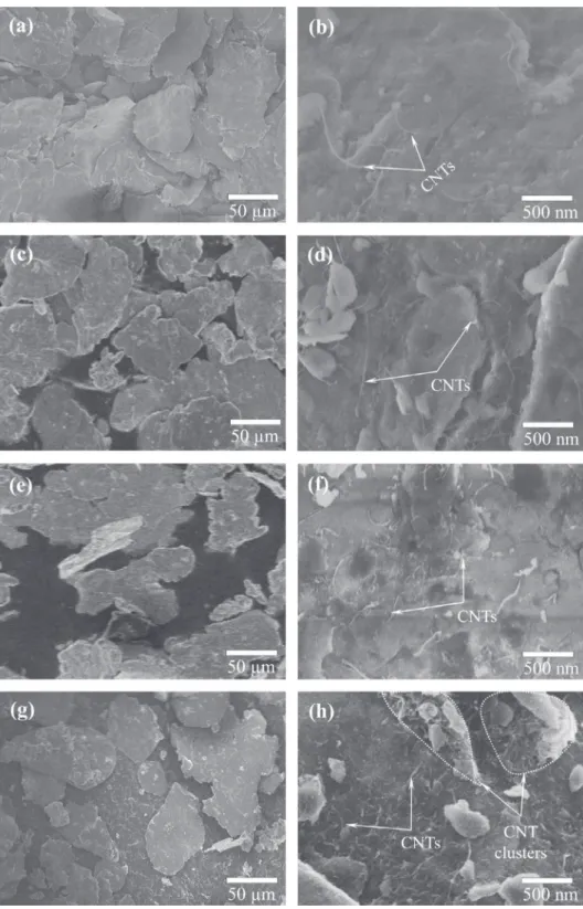
Low-magnification FESEM images of the MWCNT/Al powders
(left panel inFig. 4) show the Al flakes and do not reveal MWCNT
agglomerate or cluster, let alone individual MWCNTs.
Higher-magnification images (right panel in Fig. 4) show individual
MWCNTs well distributed on the Al flakes for the P0.5, P1 and
P1.5 powders (Fig. 4b, d, f). For powder P2 (Fig. 4h), a few MWCNT
clusters are observed laying on the Al flake surfaces, along with individual MWCNTs. The microstructure of the composite powders
is similar to that reported for milling times lower than 3 h[31].
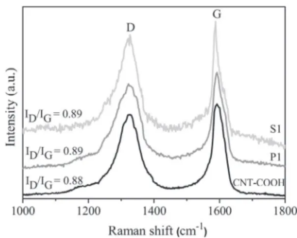
The Raman spectra (Fig. 5) of the MWCNTs, powder P1 and
sin-tered specimen S1 reveal that ID/IG, the ratio between the
intensi-ties of the D band (ca. 1320 cm"1) and the G band (ca. 1580 cm"1)
is equal to 0.88, 0.89 and 0.89, respectively. An increased ID/IG
cor-responds to an increased proportion of disordered carbon, which is generally attributed to the presence of more structural defects along the CNT walls. The almost identical values observed here show that the mixing process and the HIP process did not dramat-ically damage the MWCNTs.
Analysis of the XRD patterns (Fig. 6) of the S specimens reveals
only the Al diffraction peaks. Aluminum oxides and carbides are
not detected. By contrast, Al4C3was detected by HRTEM in
speci-mens prepared using spark plasma sintering and vacuum sintering
techniques at temperatures higher than 600 "C[18,32]. Al4C3
for-mation results from the interfacial reaction between the Al matrix and the carbon atoms from amorphous carbon or the defective
region of CNTs[18,33]. Moreover, partially damaged CNTs may also
act as carbon source for the formation of Al4C3[32]. Liu et al.[33]
showed using XRD and HRTEM that Al4C3in CNT/Al composites is
observed when the powders are ball-milled for over 4 h and is not detected for shorter milling times. Therefore, we propose that our milling and HIP experimental conditions are mild enough in order
that no detectable Al4C3is formed. It is possible that it is below the
detection limit in our XRD experimental conditions. Thus, local for-mation is not ruled out and future characterization by HRTEM
could shed light on that matter. The relative density (
q
-Table 1),calculated using 1.85 and 2.7 g cm"3 for the MWCNTs and Al,
respectively, decreases upon the increase in carbon content, from 98% for S0 to 94% for S2, which reflects that the presence of the MWCNT inhibits composite densification in agreement with
sev-eral works[18,32–37].
The specimens have been investigated by optical microscopy, considering three concentric areas (noted as Areas 1, 2 and 3) from
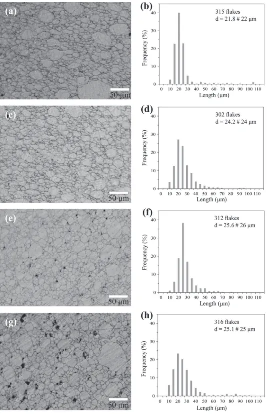
center to periphery, respectively (Fig. 7). Optical microscopy
images of the surface (Area 1) of polished and chemically etched
specimens are presented inFig. 8. For S0 (Fig. 8a), the Al grain size,
or more precisely the flake diameter distribution, is large (10–100
mm) and the average flake diameter is equal to 22 mm (Fig. 8b). This
is about half the value found for the flakes in the powder (Fig. 1d), revealing that many were broken under the applied pressure dur-ing cold compaction and/or HIP. Upon the increase in carbon con-tent, there is no significant evolution for both the flake diameter
distribution and average value (Fig. 8f, h) but some pores and/or
CNT agglomerates (clusters) are observed, as black dots about 5
and 8 mm in size for S1.5 (Fig. 8e) and S2 (Fig. 8g), respectively.
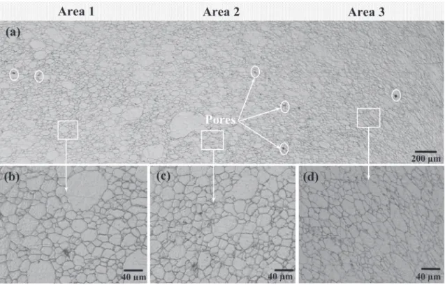
For specimen S1, the three areas were investigated into more details. A top-view image showing all three areas is presented in
Fig. 9a. A few isolated pores are observed in all of them. Higher-magnification images reveal that the Al flakes are isotropic in Area 1 (Fig. 9b) and Area 2 (Fig. 9c) whereas they appear to be elongated
in Area 3 (Fig. 9d). This could reflect the effect of non-uniform
forces caused by a gradient in specimen densification. Indeed, den-sification begins on the outside of the pressed specimen then pro-gressively affects the inner parts of the compact. The outer shell formed during the first steps of sintering may screen the inner parts from high pressure and therefore the Al flakes in Areas 2
and 1 are subject to lower pressures than those in Area 3. A
cross-section image (Fig. 10a) reveals the essentially layered
microstruc-ture of the sample and that Area 1 (center) is more porous than Area 2 and, more significantly, Area 3 (periphery). Note that all black parts in Areas 1 and 2 are not pores, but could reflect that some sample parts were removed because of the stronger influence of the etching in those areas. Higher-magnification images show that the multi-layered microstructure is much distorted at the
cen-ter (Area 1,Fig. 10b), the flakes (1–2 mm thick) being much less
aligned and ordered than at the periphery (Area 3,Fig. 10d).
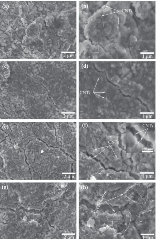
For Area 1, top-view FESEM observations were performed on
the polished and chemically etched specimens (Fig. 11). The
indi-vidual Al grains that form the flakes appear to be about 500 nm in size. Flake/flake boundaries and intra-flake micro-cracks, all less than 250 nm wide, are observed in all specimens. MWCNTs tend to
bridge the micro-cracks (inset inFig. 11f), as observed elsewhere
[38]. The MWCNTs spatial distribution is satisfactory for S0.5
(Fig. 11b), S1 (Fig. 11d) and S1.5 (Fig. 11f) whereas some MWCNT
clusters are observed for S2 (Fig. 11h) in agreement with the
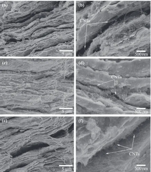
opti-cal microscopy results presented above (Fig. 8). Cross-section
FESEM images for different Areas of specimen S1 (Fig. 12) clearly
confirm the layered microstructure with flakes stacked one upon the other. Interestingly, the higher magnification images (right
panel in Fig. 12) show the surface of the MWCNT/Al flakes. The
flake/flake interface is therefore quite rich in MWCNTs, which would decrease the sintering ability.
3.2. Microhardness and coefficient of thermal expansion
The microhardness (H -Table 1) increases upon the increase in
carbon content from 44 HV (S0) to 83 HV (S1.5) but decreases to 62 HV for S2, probably reflecting both the lower densification and the higher agglomeration of MWCNTs for the latter specimen. These
results are in line with earlier reports[18,32–35,39,40]. Bradbury
et al.[37]reported a very high value (151 HV) for a MWCNT/Al
composite (6 wt% carbon), but note that it is macro-hardness (20
kg load). Yang et al.[13]reported micro-hardness up to 130 HV,
which could result from a number of factors although it is not pre-cisely determined. Further studies concerning to the effect of CNT-rich layer on the other mechanical properties such as strength and ductility will be presented in future works. Note that other researchers have demonstrated that the mechanical behavior of CNT/Al composites prepared by flake powder metallurgy can
indeed be much improved. For example, Jiang et al. [19,20,26]
reported that CNT/Al composites showed tensile strength of 375
MPa and a higher (by 12%) plasticity. Similarly, Xu et al. [24]
reported the balanced strength and ductility in CNT/Al composites. The average CTE of the composites in the temperature range
50–250 "C is shown in Fig. 13a. It increases from 50 to 150 "C
and reaches a plateau for this temperature. Interestingly the CTE plateau value (i.e. the 150–250 "C value) decreases regularly upon the increase in carbon content by about 12, 18, 25 and 30%, for S0.5, S1, S1.5 and S2, respectively, compared to the value measured
for S0. For S2, the 150–250 "C CTE is equal to 15.4 ! 10"6K"1,
which is significantly lower than results reported earlier for CNT/ Al composites with about the same carbon content and for which the authors confirmed that the CNTs are uniformly dispersed on the surface of the Al grains in the powders as well as inside the
Al matrix (Table 1). In fact, to the best of our knowledge, the only
lower values are reported for composites using nanometric-sized Al and with higher carbon contents: a 65% decrease for 15 vol%
SWCNT/Al samples (CTE # 9.8 ! 10"6K"1)[7]and a 70% decrease
for 5 wt% CNT/Al composites [12]. To evaluate the influence of
Fig. 7. Microstructure map of the sintered specimens, showing three different Areas for further investigation. See text for details. (For interpretation of the references to color in this figure legend, the reader is referred to the web version of this article.)
Fig. 6. XRD patterns of sintered specimen S0 (Al), S0.5, S1, S1.5 and S2. Fig. 5. Raman spectra of the MWCNTs, powder P1 and sintered specimen S1.
the MWCNTs on the CTE of the composite, the rule of mixtures
(ROM) (Eq.(1)) and Turner’s model referring to interconnected or
continuous reinforcement ([41,42], Eq.(2)), were used in order to
estimate the CTE of composites[7,9,10,14]:
e
c¼e
CNTVCNTþe
Alð100 " VCNTÞ ð1Þe
c¼ECNTe
CNTVCNTþ EAle
Alð100 " VCNTÞECNTVCNTþ EAlð100 " VCNTÞ ð2Þ
where
ec
,eCNT
(# 0 for MWCNTs with N = 14 walls[14]),eAl
(# 22.1! 10"6K"1) [1]are the CTE of composites, CNTs and Al,
respec-tively; ECNT(# 950 GPa)[43], EAl(# 69 GPa) are the elastic modulus
of CNTs and Al, respectively; and VCNTis the carbon content (vol%).
Note that Turner’s model will be the same than the lower bound of
Schapery’s model [14] using elastic energy principles to derive
bounds for effective CTEs of anisotropic composites made from iso-tropic constituents. The CTE values calculated using the ROM model
(open circles inFig. 13b) are not in agreement with the
tal data. This is mainly because the ROM does not take into account the interfacial thermal stress between the CNTs and Al matrix and
the Al matrix restriction influence[7,44]. By contrast, the values
cal-culated using Turner’s model are in good agreement with the exper-imental results, being only slightly higher. The model takes into account the mechanical interaction between the phases in the
Fig. 9. Top-view optical images of S1 at different positions from center to periphery: (a) global image, (b) Area 1, (c) Area 2 and (d) Area 3.
heterogeneous composite material but disregards any shape and distribution factor of particles within the composite which may hold true for low loading fractions as is the case here. The good fit could reflect, in addition to the input of the elastic constants into the calculation, the uniform dispersion of both the CNTs and
CNT-rich layer, the contribution of the MWCNT-Al interface [7,9,10],
where within a given flake there is probably a relatively good bond-ing, or also the influence of the MWCNT-rich flake/flake interfacial regions, which could be viewed as a disruption of the composite
[42]. We propose that the present layered-microstructure with a
MWCNT-rich layer located between two MWCNT/Al flakes, result-ing from the use of Al flakes as opposed to rounded particles, is mainly responsible for the low CTE measured. The MWCNT-rich layer located between two Al flakes will block the grain growth of each Al flake in the vertical direction. Al flakes were broken into smaller flakes during HIP but they are still connected together by
MWCNT bridges in the horizontal direction (Fig. 11). These MWCNT
bridges will act as joint splices to adjust the grain growth of Al
flakes in the horizontal direction. This is the reason why specimen S2, with a less uniform dispersion of MWCNTs, still has a lower CTE compared to other specimens. Thus, the layer-by-layer struc-ture, is an important factor that strongly affects the CTE of MWCNT/Al composites, together with the uniform MWCNT disper-sion. It is our opinion that none of the usual CTE models (Kerner, Schapery, Turner and Hashin-Shtrikman) is simply applicable to such complex materials where the load (MWCNTs) is highly anisotropic, the matrix grains are flake-shaped and the billet struc-ture is non-uniform. The influence of the layer-by-layer strucstruc-ture, in particular, will be modeled in a future paper.
4. Conclusions
Layered-microstructure MWCNT/Al composites were prepared by a combination of flake powder metallurgy, PBA mixing tech-nique and hot-isostatic-pressing. The composites show a layered-microstructure with a stacking of MWCNT/Al flakes 1–2 mm thick, with a MWCNT-rich layer between two MWCNT/Al flakes. The flakes however are much less ordered at the center of the specimen than at the periphery. The individual Al grains forming the flakes
are about 500 nm in size. Flake/flake boundaries and intra-flake micro-cracks, all less than 250 nm wide, are observed in all speci-mens. The MWCNTs are well dispersed within a flake and they bridge the micro-cracks. The CTE decreases markedly upon the
increase in carbon content, reaching 15.4 ! 10"6K"1for the
spec-imen with a carbon content of 2.0 wt% (2.9 vol%), i.e. a 30% decrease compared to the CTE of pure Al. Turner’s model, referring to interconnected or continuous additive, is a good fit to the exper-imental data. The low CTE measured could arise from the present layered-microstructure with a MWCNT-rich layer located between two MWCNT/Al flakes, resulting from the use of Al flakes as opposed to rounded particles. The study of a possible anisotropy of the CTE is the subject of future work.
Acknowledgements
The Vietnamese authors thank the financial support from Key Laboratory for Electronic Materials and Devices, IMS under project codes: CSTÐ 02.17. The author (PVT) also would like to thank the financial support of Erasmus Mundus Action 2 – Lotus Unlimited Project.
References
[1]Doane DA, Franzon P. Multichip module technologies and alternatives: the basics. New York: Van Nostrand Reinhold; 1993.
[2]Sidhu SS, Kumar S, Batish A. Metal matrix composites for thermal management: A review. Critical Rev Solid State Mater Sci 2016;41(2):132–57. [3]Qu XH, Zhang L, Wu M, Ren SB. Review of metal matrix composites with high thermal conductivity for thermal management applications. Prog Natural Sci: Mater Int 2011;21(3):189–97.
[4]Bakshi SR, Lahiri D, Agarwal A. Carbon nanotube reinforced metal matrix composites. Int Mater Rev 2010;55(1):41–64.
[5]Tjong SC. Recent progress in the development and properties of novel metal matrix nanocomposite reinforced with carbon nanotubes and graphene sheets. Mater Sci Eng R 2013;74:281–350.
[6]Uddi SM, Mahmud T, Wolf C, Glanz C, Kolaric I, Hulman M, et al. Thermal expansion co-efficient of nanotube–metal composites. Phys Status Solidi B 2009;246(11–12):2836–9.
[7]Tang Y, Cong H, Zhong R, Cheng HM. Thermal expansion of a composite of single-walled carbon nanotubes and nanocrystalline aluminum. Carbon 2004;42:3251–72.
[8]Deng CF, Ma YX, Zhang P, Zhang XX, Wang DZ. Thermal expansion behaviors of aluminum composite reinforced with carbon nanotubes. Mater Lett 2008;62 (15):2301–3.
[9]Liu ZY, Xiao BL, Wang WG, Ma ZY. Elevated temperature tensile properties and thermal expansion of CNT/2009Al composites. Compos Sci Technol 2012;72 (15):1826–33.
[10]Liu ZY, Xiao BL, Wang WG, Ma ZY. Effect of carbon nanotube orientation on mechanical properties and thermal expansion coefficient of carbon nanotube-reinforced aluminum matrix composites. Acta Metall Sin (Engl Lett) 2014;27 (5):901–8.
[11]Shin SE, Ko YJ, Bae DH. Mechanical and thermal properties of nanocarbon-reinforced aluminum matrix composites at elevated temperatures. Compos Part B 2016;106:66–73.
[12]Sharma M, Sharma V. Chemical, mechanical, and thermal expansion properties of a carbon nanotube-reinforced aluminum nanocomposite. Int J Miner Metall Mater 2016;23(2):222–33.
[13]Yang X, Zou T, Shi C, Liu E, He C, Zhao N. Effect of carbon nanotube (CNT) content on the properties of in-situ synthesis CNT reinforced Al composites. Mater Sci Eng A 2016;660:11–8.
[14]Shirasu K, Nakamura A, Yamamoto G, Ogasawara T, Shimamura Y, Inoue Y, et al. Potential use of CNTs for production of zero thermal expansion coefficient composite materials: An experimental evaluation of axial thermal expansion coefficient of CNTs using a combination of thermal expansion and uniaxial tensile tests. Compos Part A 2017;95:152–60.
[15]Cha SI, Kim KT, Arshad SN, Mo CB, Hong SH. Extraordinary strengthening effect of carbon nanotubes in metal-matrix nanocomposites processed by molecular-level mixing. Adv Mater 2008;17(11):1377–81.
[16]He C, Zhao N, Shi C, Du X, Li J, Li H, et al. An approach to obtaining homogeneously dispersed carbon nanotubes in Al powders for preparing reinforced Al-matrix composites. Adv Mater 2007;19(8):1128–32.
[17]Noguchi T, Magario A, Fukazawa S, Shimizu S, Beppu J, Seki M. Carbon nanotube/aluminum composites with uniform dispersion. Mater Trans 2004;45:602–4.
[18]Kwon H, Estili M, Takagi K, Miyazaki T, Kawasaki A. Combination of hot extrusion and spark plasma sintering for producing carbon nanotube reinforced aluminum matrix composites. Carbon 2009;47(3):570–7. [19]Jiang L, Li Z, Fan G, Cao L, Zhang D. The use of flake powder metallurgy to
produce carbon nanotube (CNT)/aluminum composites with a homogenous CNT distribution. Carbon 2012;50(5):193–8.
[20] Jiang L, Fana G, Li Z, Kai X, Zhang D, Chen Z, et al. An approach to the uniform dispersion of a high volume fraction of carbon nanotubes in aluminum powder. Carbon 2011;49(6):165–71.
[21]Pham VT, Nguyen VA, Bui HT, Le DC, Nguyen VC, Nguyen VL, et al. A method to obtain homogeneously dispersed carbon nanotubes in Al powders for preparing Al/CNTs nanocomposite. Adv Nat Sci Nanosci Nanotechnol 2013;4 (025015):4.
[22]Suárez S, Moore ER, Lechthaler B, Mücklich F. Grain growth analysis of multiwalled carbon nanotube-reinforced bulk Ni composites. Carbon 2014;70:173–8.
[23]Liao Z, Tan MJ. Mixing of carbon nanotubes (CNTs) and aluminum powder for powder metallurgy use. Powder Technol 2011;208(1):42–8.
[24]Xu R, Tan Z, Xiong D, Fan G, Guo Q, Zhang J, et al. Balanced strength and ductility in CNT/Al composites achieved by flake powder metallurgy via shift-speed ball milling. Compos Part A 2017;96:57–66.
[25]Fan G, Xu R, Tan Z, Zhang D, Li Z. Development of flake powder metallurgy in fabricating metal matrix composites: A review. Acta Metall Sin (Engl Lett) 2014;27(5):806–15.
[26]Jiang L, Li Z, Fan G, Cao L, Zhang D. Strong and ductile carbon nanotube/ aluminum bulk nanolaminated composites with two-dimensional alignment of carbon nanotubes. Scr Mater 2012;66:331–4.
[27]Phuong DD, Trinh PV, An NV, Luan NV, Minh PN, et al. Effects of carbon nanotube content and annealing temperature on the hardness of CNT reinforced aluminum nanocomposites processed by the high pressure torsion technique. J Alloy Compd 2014;613:68–73.
[28]Trinh PV, Luan NV, Minh PN, Phuong DD. Effect of sintering temperature on properties of CNT/Al Composite prepared by capsule-free hot isostatic pressing technique. Trans Indian Inst Met 2017;70(4):947–55.
[29]Chiodarelli N, Richard O, Bender H, Heyns M, De Gendt S, Groeseneken G, et al. Correlation between number of walls and diameter in multiwall carbon nanotubes grown by chemical vapor deposition. Carbon 2012;50(5):1748–52. [30] Laurent Ch, Flahaut E, Peigney A. The weight and density of carbon nanotubes
versus the number of walls and diameter. Carbon 2010;48(10):2994–6. [31]Esawi A, Morsi K. Dispersion of carbon nanotubes (CNTs) in aluminum powder.
Compos Part A 2007;38(2):646–50.
[32]Simões S, Viana F, Reis MAL, Vieira MF. Influence of dispersion/mixture time on mechanical properties of Al-CNTs nanocomposites. Compos Struct 2015;126:114–22.
[33]Liu XQ, Li C, Eckert J, Prashanth KG, et al. Microstructure evolution and mechanical properties of carbon nanotubes reinforced Al matrix composites. Mater Charact 2017;133:122–32.
[34]Kim IY, Lee JH, Lee GS, Baik SH, Kim YJ, Lee YZ. Friction and wear characteristics of the carbon nanotube–aluminum composites with different manufacturing conditions. Wear 2009;267(1–4):593–8.
[35]Simões S, Viana F, Reis MAL, Vieira MF. Improved dispersion of carbon nanotubes in aluminum nanocomposites. Compos Struct 2014;108:992–1000. [36]Bastwros MMH, Esawi AMK, Wifi A. Friction and wear behavior of Al-CNT
composites. Wear 2013;307(1–2):164–73.
[37]Bradbury CR, Gomon JK, Kollo L, Kwon H, Leparoux M. Hardness of multi wall carbon nanotubes reinforced aluminium matrix composites. J Alloy Compd 2014;585:362–7.
[38]Peigney A, Garcia FL, Estournès C, Weibel A, Laurent Ch. Toughening and hardening in double-walled carbon nanotube/nanostructured magnesia composites. Carbon 2010;48:1952–60.
[39]Liao JZ, Tan MJ, Sridhar I. Spark plasma sintered multi-wall carbon nanotube reinforced aluminum matrix composites. Mater Design 2010;31(1):s96–s100. [40] Yadav V, Harimkar SP. Microstructure and properties of spark plasma sintered carbon nanotube reinforced aluminum matrix composites. Adv Eng Mater 2011;13(12):1128–34.
Fig. 13. (a) CTE of CNT/Al composites versus temperature and (b) comparison between calculated and experimental CTE versus carbon content in the tempera-ture range of 200–250 "C. (For interpretation of the references to color in this figure legend, the reader is referred to the web version of this article.)
[41]Turner P. Thermal-expansion stresses in reinforced plastics. J Res Nat Bur Stand 1934;1946(37):239.
[42]Nam TH, Requena G, Degischer P. Thermal expansion behaviour of aluminum matrix composites with densely packed SiC particles. Compos Part A 2008;39:856–65.
[43]Yu MF, Lourie O, Dyer MJ, Moloni K, Kelly TF, Ruoff RS. Strength and breaking mechanism of multiwalled carbon nanotubes under tensile load. Science 2000;287(5453):637–40.
[44]Karadeniz ZH, Kumlutas D. A numerical study on the coefficients of thermal expansion of fiber reinforced composite materials. Compos Struct 2007;78 (1):1–10.