HAL Id: tel-01132857
https://pastel.archives-ouvertes.fr/tel-01132857v2
Submitted on 24 Dec 2015HAL is a multi-disciplinary open access
archive for the deposit and dissemination of sci-entific research documents, whether they are pub-lished or not. The documents may come from teaching and research institutions in France or
L’archive ouverte pluridisciplinaire HAL, est destinée au dépôt et à la diffusion de documents scientifiques de niveau recherche, publiés ou non, émanant des établissements d’enseignement et de recherche français ou étrangers, des laboratoires
machining of large aeronautical parts : Machining
quality improvement
Xavier Cerutti
To cite this version:
Xavier Cerutti. Numerical modelling and mechanical analysis of the machining of large aeronautical parts : Machining quality improvement. Mechanics of materials [physics.class-ph]. Ecole Nationale Supérieure des Mines de Paris, 2014. English. �NNT : 2014ENMP0029�. �tel-01132857v2�
T
H
E
S
E
MINES ParisTech CEMEF - UMR CNRS 76351 Rue Claude Daunesse, 06904 Sophia Antipolis, France
École doctorale n
o364 : Sciences Fondamentales et Appliquées
Doctorat ParisTech
THÈSE
pour obtenir le grade de docteur délivré par
l’École Nationale Supérieure des Mines de Paris
Spécialité “Mécanique Numérique”
présentée et soutenue publiquement par
Xavier C
ERUTTIle 04 décembre 2014
Modélisation numérique et analyse mécanique de l’usinage de
grandes pièces aéronautiques: Amélioration de la qualité d’usinage
-Numerical modelling and mechanical analysis of the machining
of large aeronautical parts: Machining quality improvement
Directrice de thèse :Katia MOCELLIN
Jury
M. Philippe LORONG, Professeur des universités, Arts et Métiers ParisTech, PIMM Président
M. Pedro-José ARRAZOLA ARRIOLA, Professeur des universités, Université de Mondragon Rapporteur
M. Jean-Michel BERGHEAU, Professeur des universités, ENISE, LTDS Rapporteur
M. Emmanuel DUC, Professeur des universités, IFMA, Institut Pascal Examinateur
Mme. Katia MOCELLIN, HDR, Maître de Recherche, MINES ParisTech, CEMEF Examinateur
Remerciements
Pour commencer, je souhaiterais remercier tous ceux qui m’ont formé, aidé et suivi et qui ont donc contribué à la réussite de ce projet.
Premièrement je tiens à remercier l’ensemble de la direction du CEMEF pour m’avoir donné la possibilité et donné les moyens de réaliser ce travail.
Je tiens également à remercier ma directrice de thèse, Katia MOCELLIN, pour son encadrement remarquable, sa disponibilité ainsi que sa bonne humeur! Nos discussions furent pour moi une grande source de motivation et ce fut vraiment un grand plaisir de travailler avec elle durant ces trois années. J’ai beaucoup appris. Merci!
Je tiens ensuite à remercier tous les membres de mon jury. Pedro-José ARRAZOLA ARRIOLA et Jean-Michel BERGHEAU pour avoir accepté et eu la patience de lire avec attention ce manuscrit ainsi que Philippe LORONG pour avoir accepté de présider ce jury. Ce fut un plaisir de vous rencontrer et de pouvoir discuter avec vous. Merci également à Emmanuel DUC et Myriam BOUET-GRIFFON pour avoir pu vous rendre présents ce jour.
Ces travaux ont été réalisés dans le cadre du Projet OFELIA. Je tiens donc également à exprimer ma gratitude à tous les acteurs de ce projet ayant contribué à sa réussite : Myriam BOUET-GRIFFON et Sylvie ARSENE (Constellium CRV), Ludovic BOURGEON et Arnaud BLANCKAERT (Aubert&Duval Issoire), Abel KHAMALLAH (Constellium Issoire), Arnaud BOIVIN (Rexiaa) ainsi que Emmanuel DUC et Sami HASSINI (IFMA). Je tiens à remercier ce dernier pour avoir partagé ses connaissances de l’usinage, des logiciels FAO et sans qui il n’aurait pas été possible d’obtenir les mesures expérimentales nécessaires pour la validation de l’outil numérique. Je tiens également à remercier toutes les personnes ayant fait de ces trois ans de thèse au CEMEF un moment agréable et enrichissant: François BAY, Yannick TILLIER, Pierre Olivier BOUCHARD, Marie-Françoise GUENEGAN, Patrick COELS et tous les autres. Je tiens bien évidemment à remercier également tous mes collègues doctorants et post-doctorants pour toutes les discussions sur nos thèses et travaux et pour tous les bons moments passés: Olivier, Ali, Dorian, Antoine, Sabrina, Romain(s), Victor, Simon, Colin et tous les autres.
Enfin, je tiens à remercier tout particulièrement mes proches, pour tout le temps avoir été présents ainsi que pour m’avoir soutenu et encouragé et sans qui rien de tout cela n’aurait été possible. Merci pour tout!
Contents
Introduction 1
Aeronautics . . . 2
Aluminium-Lithium Alloys . . . 3
The OFELIA Project: Motivation . . . 6
Presentation of the OFELIA Project . . . 6
Involvement of this Work in the Project: Problematic . . . 7
Research Objectives . . . 9
Organisation of the Dissertation . . . 10
1 Review of Literature 13 1.1 Residual Stresses . . . 15
1.1.1 Residual Stresses in Metals: Definition and Origins . . . 15
1.1.2 Residual Stress Influences . . . 16
1.1.3 The Aluminium Alloy Aerospace Part Manufacturing: Residual Stress Genesis . . . 17
1.1.4 Discussion on the Residual Stresses . . . 20
1.2 Machining Processes . . . 20
1.2.1 Machining Process Plan . . . 22
1.2.2 Discussion on the Machining Processes . . . 42
1.3 Simulation of the Milling Process at Part Scale: Prediction of the Machining Quality . . . 43
1.3.1 Numerical Methods for Material Removal . . . 43
1.3.2 The FE Models for the Prediction of the Machining Distortion . . . 47
1.3.3 Discussion on the Prediction of the Machining Quality . . . 48
1.4 Establishment of the Assumptions . . . 49
1.6 Résumé en Français . . . 52
2 FORGE OFELIA 55 2.1 The Finite Element Software FORGE�. . . . 57
2.1.1 The Mechanical Problem . . . 57
2.1.2 Finite Element Formulation . . . 63
2.1.3 Contact Analysis . . . 64
2.1.4 Resolution . . . 66
2.1.5 Automatic Remeshing and Field Transfer . . . 67
2.2 FORGE OFELIA [124] . . . 68
2.2.1 Numerical Approach for Machining . . . 68
2.2.2 Parallelization of the Code . . . 78
2.2.3 Automated Mesh Refinement . . . 81
2.3 The Different Levels of Modelling . . . 85
2.4 Numerical Comparison with a Different Modelling Approach . . . 88
2.4.1 Case Studied . . . 88
2.4.2 The Model: Results . . . 89
2.5 Conclusion . . . 94
2.6 Résumé en Français . . . 95
3 The AIRWARE�2050 Alloy Residual Stress Distribution 97 3.1 The Layer Removal Method . . . 99
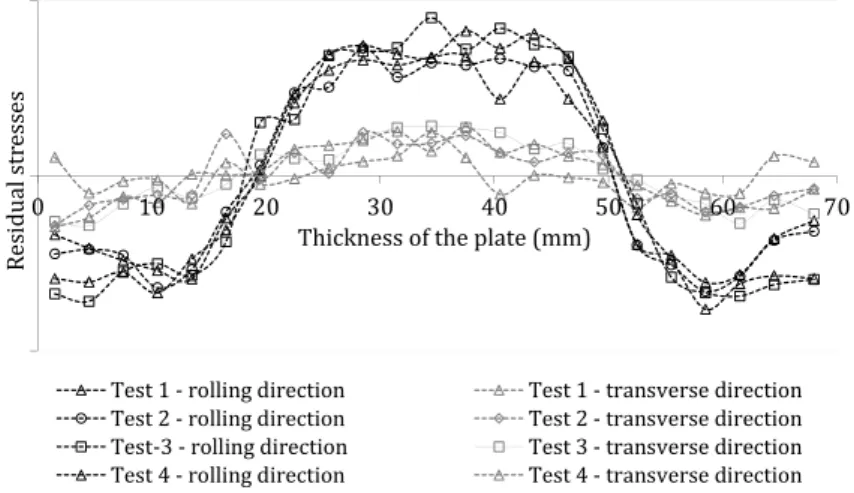
3.1.1 Experimental Results: AIRWARE�2050 Alloy Residual Stress Profiles . . 99
3.1.2 Analysis of the Residual Stress Profiles . . . 103
3.2 Simulation of the Layer Removal Method . . . 105
3.2.1 Polynomial Approximation of the Residual Stress Profiles . . . 106
3.2.2 The Numerical Approach . . . 106
3.2.3 Simulation Results . . . 108
3.2.4 Discussion . . . 110
3.3 Post-Machining Distortion Prediction: Validation Tests . . . 112
3.3.1 Machining of an "Open Pockets" Case [124] . . . 112
3.3.2 Discussion . . . 117
3.4 Machining Part Quality Analysis: Initial Residual Stresses and Machining Sequence Influence . . . 118
Contents
3.4.1 Definition of the Case Study . . . 118
3.4.2 Reference Machining Case . . . 120
3.4.3 Machining Part Quality Improvements . . . 123
3.4.4 Discussion . . . 133
3.5 Conclusion . . . 134
3.6 Résumé en Français . . . 135
4 Machining Process Plan Optimisation 137 4.1 Influence of the Parameters . . . 139
4.1.1 Machining Process Plan Parameters . . . 139
4.1.2 Machining Quality Evaluation: Measurements . . . 141
4.1.3 Machining Process Plans with a 70 mm Thick Rolled Plate: Minimal Use of Material . . . 143
4.1.4 Machining Process Plans with a 90 mm Thick Rolled Plate . . . 150
4.1.5 Discussion . . . 158
4.2 Methodology to Improve the Machining Quality . . . 159
Influence of the Parameters . . . 159
4.2.1 Procedure . . . 159
4.2.2 Machining Process Plan Definition: Guidelines . . . 162
4.2.3 Application of the Methodology . . . 164
4.2.4 Discussion . . . 167
4.3 Conclusion . . . 168
4.4 Résumé en Français . . . 169
5 Simulation of Large Aerospace Parts 171 5.1 Machining of Rolled Plate . . . 173
5.1.1 The Geometry . . . 173
5.1.2 Industrial Machining Process Plan . . . 173
5.1.3 Simulations . . . 175
5.1.4 Discussion . . . 183
5.2 Machining of a Forged Part . . . 185
5.2.1 Presentation of the Case . . . 185
5.2.2 Results . . . 186
5.3 Conclusion . . . 190
5.4 Résumé en Français . . . 190
Conclusion and Perspectives 193 Conclusion . . . 193
Perspectives . . . 196
Bibliography 201 A OFELIA Project 213 B The Layer Removal Method: Residual Stress Redistribution 217 C Machining of a "Closed Pockets" Case 221 D Results Presented in Chapter 4 225 D.1 70mm Thick AIRWARE�2050-T84 Alloy Rolled Plate: Thickness Variations . . . 225
D.2 90mm Thick AIRWARE�2050-T84 Alloy Rolled Plate . . . 226
D.2.1 Post-Machining Distortions . . . 226
Introduction
ContentsAeronautics . . . 2
Aluminium-Lithium Alloys . . . 3
The OFELIA Project: Motivation . . . 6
Presentation of the OFELIA Project . . . 6
Involvement of this Work in the Project: Problematic . . . 7
Research Objectives . . . 9
Aeronautics
According to forecasts, air traffic is expected to more than double over the next 15-20 years with an increase of approximately 4.7% [1] per annum. The aerospace industry is therefore booming and is facing an increasing demand [2]. This represents a need for approximately 30,000 new planes, a third of them replacing older ones. The aviation industry is thus very healthy and presents a high potential of economical growth (see Figure 1).
Figure 1: Forecasts of the development of air traffic and the number of new aircrafts needed by 2032 [1]
Aeronautics requires the implementation of sophisticated technologies with an absolute secu-rity, resulting in the need of a high mastery of every process which has led the aviation industry to significant investments into R&D programs. For example, the technological progresses
made during the last 40 years have already allowed to reduce the fuel consumption and CO2
emissions by 70% as well as noise by 75% compared to levels in 1970, while passengers benefit from an increasing level of comfort [1]. This progress results in a continuous improvement of technologies used in the construction of aircrafts which is itself the result of the numerous R&D programs. Competition in the aviation industry is therefore increasing and industries face many challenges to produce even more efficient parts with increasingly shorter lead times, using the most advanced materials. The production of relatively small series requires production flexibility, making the fulfilment of these expectations even harder.
The aim to improve the efficiency and to minimise the environmental impact of planes has become a priority and therefore a major area of research and innovation in aeronautics. One way to achieve the objective of more efficient and more environmentally friendly planes is the manufacturing of lighter parts with better mechanical properties and the use of the smallest amount of resources (material, energy) possible to produce them. Both the development of new grades and the optimisation of the manufacturing processes are therefore solutions. This need has already led to an increase in the use of composite materials for aircraft construction. However, in new planes aluminium still represents up to 20% of the weight (see Figure 2) and with the arrival of new alloys this percentage may well increase.
Aluminium-Lithium Alloys
Figure 2: Distribution of materials by percentage of weight of the aircraft [3, 4] structural parts made of aluminium are large monolithic parts, thereby lowering the weight of the parts in minimizing the use of assembly equipment (bolts, screws, etc). The manufacturing of increasingly larger monolithic parts in aeronautics is also intensified by the need to reduce the assembly costs which can represent up to 50% of the total costs of delivered parts [5]. These large monolithic parts are usually made from aluminium prismatic blocks or from preformed parts (forging, stamping) of which up to 90% of the weight of the raw material is removed by machining operations. One of the terms commonly used to express this characteristic is the "buy-to-fly" ratio, which represents the ratio between the weight of raw material purchased to manufacture the part and the weight of the final part (flying part). Some examples of structural aluminium alloy aircraft parts are presented in Figure 3. The large monolithic structural parts usually present a high "buy-to-fly" ratio and a lot of added value due to the manufacturing steps and to the amount of material required to obtain the final part. These parts are thus very expensive to produce. Machining is the last manufacturing step where the finished product is obtained and is therefore a crucial step in the global manufacturing of aeronautics aluminium alloy parts.
Aluminium-Lithium Alloys
Among new aluminium alloys developed to meet these new challenges the Al-Cu-Li alloys have reached the leading position. Al-Li and especially Al-Cu-Li alloys are very interesting for aeronautics. With lithium (the lightest metallic element) these alloys present a lower density as well as higher elastic properties compared to conventional high strength alloys such as the 2XXX and 7XXX series. Using 1% lithium of the total mass, the alloy density drops by about 3% while its Young’s modulus will be increased by about 6% (valid for a Li content of up to 3%) [7, 8].
Figure 3: Machining examples of large aerospace monolithic parts made of aluminium alloy [6]
first appearances of lithium in aluminium alloys go back to the 1920s, but the first generation of aluminium-lithium alloys has emerged only in the 1960s with the arrival of the AA2020 alloy (Alcoa in 1958, USA) and then VAD23 (1961, USSR) [9].
However, the development of modern aluminium-lithium alloys (second generation) really began after the oil-shocks of the late 1970s and early 1980s. This second generation comprised mainly the alloys AA2090, AA2091, AA8090 and AA8091. These alloys contained more than 2% of lithium in their weight and therefore had lower densities (about 7-10% compared to conventional alloys of the same strength used at that time). They were used primarily for military applications and achieved very limited commercial success, mainly because of technical problems due to the strong anisotropy and to the particularly low toughness and corrosion resistance under stress causing many cases of rupture during riveting operations for example [7].
The alloys of the new generation that emerged in the 1990s contained less lithium than previous alloys, thereby avoiding the technical problems encountered before. The first alloy of the new-generation alloys was the Weldalite 049 (AA2094) followed by a refined version of the original AA2195 alloy. This alloy was selected for the Space Shuttle (U.S. Space Shuttle Super Light Weight Tank) allowing a reduction in weight by 3,400 kg of a total weight of the
Aluminium-Lithium Alloys
Figure 4: The first developments and uses of lithium in aluminium alloys [9]
space shuttle of 27,000 kg. Three other alloys of the new generation were then developed: AA2096, AA2097 and AA2197. These alloys exhibit improved fatigue properties which allow for example to double the service life of parts such as the BL 19 Longeron of the F16 military aircraft compared to the alloy used previously (2124) [10]. Despite the fact that these alloys are more expensive than conventional alloys they are more economical on the long term. It has for example been shown that the AA2098 has an improvement in life time of the factor six compared to the AA2024. This alloy was then selected for the fuselage of the F16 military aircraft [8].
In the past, aluminium-lithium alloys have not achieved a great commercial success because in addition to the problems encountered in the mechanical properties of these alloys (anisotropy), they were also difficult to produce. The arrival of new and more efficient addition techniques of lithium [11] have given a fresh boost to these alloys making them one of the cutting-edge materials for aerospace.
Among the new aluminium-lithium alloys, the ones using the AIRWARE� technology
de-veloped by Constellium are the most advanced. They have been specially dede-veloped for aeronautics and space and combine uniquely strength, lightness, durability and recyclability.
They have notably been chosen by Bombardier for the fuselage of the CSeries aircraft and by SpaceX for the Falcon 9 rocket.
The product range includes the AIRWARE�2050 alloy for thick products. It is an alloy offering
a high strength and high damage tolerance. The chemical composition of the AIRWARE�2050
alloy, which is presented in Table 1, has been specially chosen to obtain a very good balance in its properties and at the same time to avoid element additions which can cause undesired
behaviour. In other words, the AIRWARE�2050 alloy has been developed using an optimised
chemical composition allowing to ensure thermal stability, to achieve the required strength level and to maximise the strength-toughness balance.
Table 1: The AIRWARE�2050 alloy’s chemical composition
% by weight Si Fe Cu Mn Mg Zn Li Ag Zr
Min 3.2 0.20 0.20 0.7 0.20 0.06
Max 0.08 0.10 3.9 0.50 0.60 0.25 1.3 0.70 0.14
The mechanical properties of the AIRWARE�2050 alloy (the main ones being summarised in
Table 2) substantially exceed those of conventional alloys including the 7050 alloy very com-monly used in aeronautics. For more details on the choice of the addition elements interested
readers can refer to [12]. The AIRWARE�2050 alloy is particularly used in the manufacture of
large structural parts where significant machining operations are generally performed. More
specifically, the alloy used for these parts is the AIRWARE�2050-T84 alloy. This state of the
AIRWARE�2050 alloy is obtained by performing multiple thermo-mechanical treatments after
the forming process (which are described later in this dissertation in Section 1.1.3). Within
this document the AIRWARE�2050-T84 alloy will always be cited as the AIRWARE�2050 alloy.
Table 2: Main mechanical properties of the AIRWARE�2050 alloy at room temperature (20 °C)
Young’s Modulus (E) Poisson’s Ratio (ν) Density (ρ) Tensile Yield Strength
75000 MPa 0.33 2693 kg /m3 500 MPa
The OFELIA Project: Motivation
Presentation of the OFELIA Project
The work presented in this dissertation has been carried out in the framework of theOFELIA
project which aims to optimise the eco-efficiency of the AIRWARE�alloys sector for the
aeronautic industry ("Optimisation d’uneFilièreEco-efficiente AluminiumLithium pour
The OFELIA Project: Motivation
Viaméca" in the scientific topic of "Advanced manufacturing processes". Its main objec-tive is to develop an optimised manufacturing chain for complex aeronautics parts made
of AIRWARE�2050 alloy. More specifically, the project objective is to optimise the global
manufacturing going from the semi-finished product (forged part, rolled plate) to the recycling of the machining chips. The improvement of the eco-efficiency of the sector aims to minimise both the environmental impact by optimising the use of resources and the costs (economic efficiency).
The OFELIA project gathers three industrial (Constellium, Aubert&Duval, Rexiaa) and three academic (Cemef, IFMA, SPIN) partners and is structured in five tasks. More information on the project organisation and partners can be found in Appendix A.
Involvement of this Work in the Project: Problematic
The work presented in this dissertation has as main objective the prediction of the machined part quality depending on the machining process plan used in order to develop machining process plans taking into consideration the mechanical behaviour of the workpiece due to its manufacturing history and therefore to improve the machining quality.
The machining quality can be defined as the machining process plan’s capability to produce parts with the desired geometrical and dimensional characteristics. The fewer differences between the final machined part and the designed one (CAD) occur the better the quality of the part. The machined part quality is defined by macro-geometrical properties such as the accuracy of dimensions, form and position of geometrical elements [13]. The part quality is strongly governed by the parameters of the machining process which can all cause disturbances. Five different machining parameters can be defined:
- The fixture - The tool path
- The machining sequence - The cutting conditions
- The mechanical state and the dimensions of the initial workpiece
All these parameters can have a more or less significant influence on the global part quality. In a traditional industrial environment, the choice of the machining parameters is often based on the experience and expertise of the process engineers and machinists. There is therefore almost no rule available based on scientific analysis in the definition of machining process plans.
Influences of parameters such as the manufacturing technique (forged part or rolled plates) of the initial workpiece are often not taken into account in the definition of the machining process plan. The consequences of neglecting some of the machining parameters and their influence on the machined part quality can lead to several costly machining trials to validate a machining process plan, to unexpected extra conforming steps after machining to obtain a conforming part or in the worst case to reject. To improve the cost-efficiency of the machining
processes, the initial workpiece is often chosen to have the shortest machining time and the smallest amount of material used as possible, despite the fact that the choice of the initial workpiece has a significant influence on the machining quality. The workpieces having undergone several manufacturing steps (forming processes and/or heat treatments) always contain residual stresses. When a section of a workpiece that possesses residual stresses is removed by machining, the initial equilibrium state of the block (plate or preformed part) is broken. A new state of static mechanical equilibrium is therefore obtained resulting in part distortion. Depending on the manufacturing steps performed previously to the machining, the workpiece exhibits different residual stress distributions. A change in the choice of the initial workpiece can therefore have a significant influence on its behaviour during the machining process.
In the past, several studies have been realised on the influence of the different machining parameters but most of them are applied on parts with simple geometries and are not adapted to our industrial problematic (large and complex structural parts with multiple machining features) [14, 15, 16]. Only a few studies have been performed on the combined effects of the parameters and their impact on the global part quality [17, 18]. These studies have nevertheless shown some limitations:
- The numerical method used to perform the material removal makes it difficult to simu-late the machining of large and complex aluminium alloy aerospace parts (the size of the simulated part is often decreased and the geometry often simplified).
- The numerical methods (material removal technique, element type) used make it diffi-cult to simulate the machining of aluminium alloy aerospace parts made from work-pieces obtained with different manufacturing methods (like forging).
- Only the post-machining distortions are predicted. The dimensional and geometrical variations due to the workpiece deflections during the machining depending on the machining process plan used are neither considered nor predicted.
The main objective of this work is therefore the development of a numerical approach and tool to predict deflections during machining as well as post-machining distortions of large and complex aerospace parts depending on the machining process plan used. In other words, this numerical tool has to be able to predict the final shape and dimensions of the parts to analyse the quality of the machining process plan. This work aims to offer an evolution in the establishment of machining process plans of aluminium structural parts by proposing rules of chronological sequencing of the machining operations and of the choice of the fixture-layout depending on the residual stresses in the workpiece and the geometry of the designed part.
The need for this study is further enhanced by the use of new alloys such as the AIRWARE�
2050 alloy whose machining behaviour has not been extensively studied. This work therefore presents both scientific and economic challenges.
Scientific challenges:
The numerical tool developed will allow to understand the various phenomena occurring
Research Objectives
influence of the different parameters. This work will therefore enable to determine the param-eters of first order (with the biggest influence) and to determine rules to ensure the desired machining quality. In addition, it will allow to accurately predict the final geometry and the stress state of the parts at the end of the manufacturing line. This will give the possibility to model the behaviour of a part in service in taking into account its whole manufacturing history (including machining). It will be possible to study for example the influence of the final geometry on the assembly process and stress state of the global structure, the influence of the final stress state of the part on the mechanical strength (fatigue, crack growth) as well as the optimisation of the entire life cycle of a part.
Economic challenges:
By predicting the machining quality, the numerical tool developed will provide a better con-trol of the machining process and the possibility to optimise the machining process plan to ensure the accuracy and quality aimed at. This will avoid the rejection of parts due to the non-conformity with dimensional and geometrical specifications as well as the realisation of extra-conforming steps to decrease the post-machining distortions and to make the part compliant with the tolerance specifications. The prediction of the machining quality and the optimisation of the machining process plan will therefore help to enhance both the productiv-ity and the machining process robustness.
A strong collaboration between project stakeholders was necessary to fulfil the objectives of the work presented in this dissertation:
- With Aubert&Duval and Constellium CRV: to determine the residual stress state of the workpiece before machining (rolled plates or forged parts) as well as the main
thermo-mechanical characteristics of the AIRWARE�2050 alloy.
- With IFMA: to make the connection between CAD/CAM software and the numerical tool developed to predict the machining quality as well as the comparison between simulation and experimental results.
- With Constellium Issoire, REXIAA and LUSINA: to use their experience and knowledge of the machining of large aerospace aluminium alloy parts and to come as close as possible to the industrial problem.
Research Objectives
The main objective of this work is to meet needs of the aerospace industry in giving the possibility to optimise and to validate a machining process plan to obtain the desired part quality before going into real machining. If the predicted machined geometry lies outside the tolerance specifications, the part is defective and the parameters of the machining process plan have to be changed. The requirements are therefore to predict the workpiece deflec-tions during the machining as well as the post-machining distordeflec-tions of large and complex
To fulfil this purpose, the research objectives of this Ph.D. work are:
� To review the literature on the machining of aluminium alloys and to establish
assump-tions on the machining parameters’ influence on the machining quality.
� To develop a modelling approach to simulate the machining of complex and large
AIRWARE�2050 alloy aerospace parts based on the previously established assumptions.
� To develop numerical methods based on the approach chosen.
� To develop a numerical method which gives the possibility to use both experimentally
and numerically determined residual stress distributions as input.
� To integrate all the numerical methods into the FORGE 2011�environment in order
to obtain the numerical tool FORGE OFELIA: the version of FORGE�adapted to the
simulation of the machining of large and complex parts made of aluminium alloys.
� To analyse the influence of the different parameters in order to develop a procedure for
the definition of machining process plans adapted to the initial residual stresses and therefore to the mechanical behaviour of the workpiece.
Organisation of the Dissertation
The presentation of this research work on the prediction of the machining quality of large and
complex AIRWARE�2050 alloy aerospace parts revolves around five chapters.
In the first chapter, a review of literature is presented which constitutes a background for the whole dissertation. First, an introduction on the residual stresses and their development during the manufacturing is realised. The machining process plan parameters (the cutting conditions, the fixture and the machining sequence and tool path) are then presented and reviewed with a particular attention on the machining of aluminium alloys. Then the different numerical material removal techniques and models developed to simulate the machining are revised. Finally, conclusions are drawn from the reviews of literature and assumptions adapted to the objectives of this project are established.
Chapter 2 is dedicated to the numerical developments. In the first section, a brief summary on the mechanical problem and solving using the mixed velocity-pressure formulation of
FORGE 2011�is performed. Details on the numerical methods used for contact modelling,
automatic remeshing and field mapping are also briefly introduced. Then, the developments
performed to create FORGE OFELIA, the version of FORGE 2011�adapted to the machining
simulation, are described. The methods used for the computation of the initial residual stresses, for the material removal as well as the adaptation of the contact analysis are detailed.
The implementation of these methods in FORGE 2011�is then discussed, followed by the
parallelization of this procedure. The options developed to increase the accuracy of the cutting are also presented. The last section focuses on the different models which can be created using FORGE OFELIA followed by a numerical validation by comparing with literature results.
Organisation of the Dissertation
Chapter 3 presents the study of the residual stress state of two rolled plates with different
thick-nesses made of AIRWARE�2050 alloy. First, the layer removal method used to determine the
residual stress profiles of both plates is presented and the results obtained are analysed. Simu-lations of these experiments are then performed which allow a first experimental validation of the numerical tool. An example of the machining of a part is also simulated and compared to experimental results, showing again the validity of the approach and of the numerical tool for the prediction of the post-machining distortion. Then, a more in-depth study on a simplified machining case, on which the two main problems of machining non-quality are highlighted, is performed. An analysis of the influence of the initial residual stresses and of the machining sequence on the geometrical and dimensional errors is thus realised. The feasibility to improve the machining quality using the developed numerical tool is then demonstrated.
Chapter 4 is devoted to a complete analysis of the influence of the machining process plan parameters on the machining quality. The case studied is a more complex part requiring several machining steps. A complete analysis of the fixture, machining sequence and initial workpiece has been performed on this part. From the results observed, a classification of the parameter influences has been realised and a procedure as well as guidelines for the definition of the machining process plan taking into consideration the mechanical behaviour of the workpiece have been developed.
In Chapter 5, the developed numerical tool is tested on two industrial cases. The first case is a large and complex structural part machined from a rolled plate whereas the second one deals with a part machined from a forged workpiece. The objective is to show that the developed numerical tool can also be used to study and to optimise the machining of complex industrial parts.
Chapter 1
Review of Literature
This first chapter is dedicated to a complete review of literature on the different aspects linked to the prediction of the machining quality. This literature review is organised in three main sections and is used as a reference for the whole study.
In the first section a brief introduction on the residual stresses, their origins and the residual stress genesis during the manufacturing of aluminium parts is realised.
Then, in a second section, previous work realised on machining processes and more specifi-cally on the milling of aluminium alloys and the parameters possibly influencing the machin-ing quality is studied.
In the third section, the different numerical methods to simulate the material removals as well as the different models used to predict the machining quality are presented.
Contents
1.1 Residual Stresses . . . 15 1.1.1 Residual Stresses in Metals: Definition and Origins . . . 15 1.1.2 Residual Stress Influences . . . 16 1.1.3 The Aluminium Alloy Aerospace Part Manufacturing:
Residual Stress Genesis . . . 17 1.1.4 Discussion on the Residual Stresses . . . 20 1.2 Machining Processes . . . 20 1.2.1 Machining Process Plan . . . 22 1.2.1.1 Cutting Conditions . . . 22 Cutting Forces . . . 23 Heating During Cutting . . . 28 Residual Stresses Induced by Machining . . . 33 1.2.1.2 Fixture . . . 35 Fixture Elements . . . 35 Fixture Design . . . 36 Machining Fixture Analysis . . . 38 1.2.1.3 The Machining Sequence and the Tool Path . . . 41 1.2.2 Discussion on the Machining Processes . . . 42 1.3 Simulation of the Milling Process at Part Scale:
Prediction of the Machining Quality . . . 43 1.3.1 Numerical Methods for Material Removal . . . 43 1.3.1.1 The Deactivation Method . . . 43 1.3.1.2 The Massive Removal Approach . . . 46 1.3.1.3 The Level-Set Method . . . 47 1.3.2 The FE Models for the Prediction of the Machining Distortion . . . 47 1.3.3 Discussion on the Prediction of the Machining Quality . . . 48 1.4 Establishment of the Assumptions . . . 49 1.5 Conclusion . . . 51 1.6 Résumé en Français . . . 52
1.1. Residual Stresses
1.1 Residual Stresses
In order to achieve a better understanding on the residual stresses, a brief introduction on their origins and influences is realised in this section. The residual stress genesis and control during the manufacturing of aluminium alloy parts is also presented.
1.1.1 Residual Stresses in Metals: Definition and Origins
Residual stresses can be defined as self-equilibrated stresses (tensile and compression stresses) existing in a solid material which is not submitted to any external load (thermal or mechanical). They can arise from different sources and can be structured in four different categories [19, 20]. - The two first sources are the unequal plastic deformations resulting from mechanical
and thermal loads.
- The third source is the metallurgical structure changes. During solid state transfor-mations a release of latent heat, change in dimensions and transformation plasticity occur, resulting in a change of the residual stresses inside the part. The difference in volume between two coexisting phases in the presence of an external load generates microscopic plasticity leading to macroscopic plastic flow [21].
- The last source of residual stresses is a mismatch in the thermal expansion coefficients. Manufacturing processes being complex combinations of these sources [22], residual stresses cannot be avoided and can be considered as outcomes of the manufacturing processes. Fig-ure 1.1 illustrates the coupling of temperatFig-ure, stress and metallurgical changes (microstruc-ture) which causes the development of residual stresses during manufacturing.
Figure 1.1: The coupling of temperature, stress and metallurgical changes [23] Residual stresses are also categorised in three types in function of the length scale over which they act [19, 24].
“Type I” are macroscopic residual stresses and are almost homogeneous across distances equal to several grains. They affect a large number of grains or the whole mechanical part. The forces and moments associated are in equilibrium in any cross-sectional plane throughout the complete body. A change in this equilibrium will lead to macroscopic dimension changes.
“Type II” are homogeneous microscopic residual stresses. They act at the microstructure scale (grain size at maximum). The forces and moments associated are in equilibrium across a sufficient number of grains. They are almost always present in polycrystalline materials because of the heterogeneity and anisotropy of each crystal or grain (grain orientations). Changes in the microstructure therefore lead to the creation of “Type II” residual stresses. A change in the equilibrium will create microscopic deformations which can also cause macroscopic dimension changes.
“Type III” are heterogeneous microscopic residual stresses. The forces and moments associated are in equilibrium over a small part of the grain. Changes in the equilibrium will not lead to macroscopic dimension changes.
In Figure 1.2 illustrations of these three residual stress categories are shown.
a) b)
Figure 1.2: Illustration of the residual stress types: a) [25]; b) [24] 1.1.2 Residual Stress Influences
Whether it is to improve the final properties of parts or to optimise the manufacturing steps, the study of residual stresses and their effects on the mechanical behaviour of parts have become one of the major interests in the manufacturing industry. Because residual stresses are sources of manufacturing defects and problems and because they can significantly alter the mechanical behaviour of parts, the interest in mastering them and their effects is particularly high in aerospace [26, 20].
1.1. Residual Stresses
When a part containing initial residual stresses (σI RS) undergoes thermal or mechanical loads,
in-service stresses σS are created in the part and will be added to the initial residual stress
fields. The real stress state of the part σRealcan therefore be defined as σI RS+σS, as illustrated
in Figure 1.3. σIRS σS σReal x y overloading relieving
Figure 1.3: Illustration of the real stress state of a part linked to the addition of the residual stresses and in-service stresses
Residual stresses play therefore an important role in the mechanical strength, fatigue strength and stress corrosion cracking [26]. For example, the superposition of the residual stresses and cyclic stresses can have a significant influence on the fatigue strength of materials. Depending on the distribution pattern of residual stresses the fatigue strength and stress corrosion resis-tance of parts will be improved or degraded. Failure due to fatigue and stress corrosion are two mechanisms initiated in surface areas of parts. Surface compressive residual stresses allow to prevent failure [27]. Specific processes as shot-peening have therefore been invented and are used in order to generate uniform compressive residual stress patterns and to eliminate microscopic defects nearly without any changes in the geometry of the part [28, 29].
Because residual stresses lead to the distortion of parts, problems can also occur during the manufacturing and the assembly processes. As explained in the Introduction, the machining process is especially concerned with non-quality problems linked to the redistribution of residual stresses. The machining inaccuracies and distortions can also have a significant impact on the assembly process. A small distortion on each part can generate a domino effect and lead to significant residual stresses in the final structure or even to the impossibility to assemble the parts. Moreover, additional steps can sometimes be required for distortion correction, thus increasing the manufacturing costs.
The interest of mastering residual stresses and associated distortions is therefore very high. The incorporation of the residual stress effects into the design and the manufacture phases of parts can allow to significantly improve the quality and final properties of products.
1.1.3 The Aluminium Alloy Aerospace Part Manufacturing: Residual Stress Genesis
Aerospace parts are usually machined from rolled plates or forged parts. In a first step, the mix of alloying elements is melted and cast into an ingot. To obtain a plate, the ingot is then hot-rolled before being heat-treated and quenched. The quenching step allows to
avoid precipitation but also produces high levels of residual stresses. In order to decrease these residual stresses, a mechanical stress relief operation is realised by stretching [30]. It is performed in the rolling direction until a uniform plastic strain of about 4% is reached [12]. To achieve precipitation strengthening, thermal aging is finally performed. Figure 1.4 illustrates
the needed successive manufacturing steps to obtain the AIRWARE�2050-T84 alloy rolled
plates. ROLLING 45b D 5bb°C QUENCHING D Quenching speed and quenchants D Quenching technology Timmersion: sprinkling:%%%f D Quenching temperature D ThermoDdependent physical properties Residual stresses after quenching STRESS RELIEF: STRETCHING
Direction of stretching and strain k Residual stresses after
stress relief AGING Aging parameters Residual stresses before machining T8b5bDT84f
Figure 1.4: Illustration of the AIRWARE�2050 alloy manufacturing line for rolled plates: the
1.1. Residual Stresses
For forged parts, the forming is also performed with a hot working process. At the end of the forging, parts are heat-treated and quenched. Mechanical stress relief operations are also performed to suppress the high residual stresses induced during quenching. These operations are done by cold compression and then, depending on the case, thermal aging can be performed additionally. However, the residual stress patterns in a forged part are not uniform like they are in rolled plates. The determination of residual stresses is therefore more complex for forged parts than for rolled plates.
Overall, residual stress distributions are complex to determine. The multiple sources and their interactions (mechanical, thermal, metallurgical) make the use of analytical analyses almost impossible. The understanding of residual stresses can therefore only be realised by two approaches, the experimental trials and the numerical modelling. Purely experimental approaches being often expensive, numerical modelling and especially finite element mod-elling is nowadays commonly used in the numerical analysis of manufacturing processes and great progress has been made in this field during the last few decades. In addition, numerical modelling is a cost-effective approach allowing a closer and more in-depth understanding. However, the quality of the modelling is strongly governed by inputs like the material be-haviour. Experimental and numerical approaches are therefore required when dealing with residual stresses and distortion [19].
To achieve the objective of a good understanding of residual stresses and their effects, several measurement methods have thus been developed. Depending on the residual stress type and the part’s characteristics the measurement techniques used have to be adapted [31]. A list of possible measurement techniques can be found in Table1.1. Figure 1.5 allows to determine which method has to be used depending on the manufacturing process and the measurement depth.
Table 1.1: Different residual stress measurement techniques [31, 25]
Technique Residual stress type Comments
Hole drilling Type I Semidestructive
Sectioning Type I Destructive
Layer removal Type I Destructive
X-Ray Type I, II & III
Non-destructive, only surface measurements, sensitive to grain size
(difficult with aluminium alloys) Neutron
diffraction Type I & II Non-destructive, costly
Ultrasonics Type I, II & III Non-destructive, microstructure-sensitive
Magnetic Type I, II & III Non-destructive, microstructure-sensitive,
Figure 1.5: Measurement techniques depending on the processes, depth of measurements and failure [32]
1.1.4 Discussion on the Residual Stresses
Residual stresses are present in all manufactured parts and are created all along the manufac-turing line. They can have both benefits and drawbacks for the final mechanical properties of the part. The determination of residual stresses can be realised using both numerical modelling and experimental measurements, the best approach being a mix of both.
In the OFELIA project, both experimental and numerical approaches have been investigated for rolled plates and a forged part. This work is partly described in Chapter 3 for the rolled plates. The prediction of the residual stress distribution of a forged part has been performed on a complex industrial case by one of the industrial partners. The results will be briefly discussed in Chapter 5.
1.2 Machining Processes
Machining processes are subtractive manufacturing methods which consist in the realisation of multiple removals of material by cutting an initial workpiece to obtain the desired final part. The machining gathers several kinds of processes which can be classified in four categories:
1.2. Machining Processes - The drilling process
- The milling process
- Specific machining processes
The three first categories are the machining processes commonly used in all industries. The last one is composed of all specific or relatively new machining processes such as grinding, sawing, electrical discharge machining (EDM), electro-chemical machining (ECM) or even the laser and water jet cutting processes. The machining process has to be chosen depending on the part geometry, surface texture and desired accuracy.
In aeronautics manufacturing industry, the milling process is most frequently used, especially when machining large aerospace aluminium alloy parts. This process is therefore the one considered in the whole study presented in this dissertation.
The milling process is a machining process where the removal of material is performed with a rotating cutting tool composed of several cutting edges (milling cutter). Usually the workpiece is moved against the rotating milling cutter, in function of the material removal required, to obtain the desired final geometry. In some cases, the milling tool can move against the fixed workpiece. Milling allows the machining of simple (plane surface) as well as of complex geometries (curved and irregular surfaces).
The first milling machine appeared in the 1810s and technologies have since never stopped evolving. The most significant evolutions in the machine tool industry occurred in the 1950s with the development of the first Numerical Control machine at MIT and then in the 1970s-1980s with the development and implementation of the Computer Numerical Control (CNC) in industry [33]. CNC technology has allowed a significant improvement in the manufacturing of parts by offering more flexibility, shorter delivery times and the capacity to produce an enormous range of geometrically complex parts for various kinds of materials and dimensions from micro- to multi-metre sized parts [34, 35]. To face the new challenges and the increasing need of productivity and quality, efforts to improve CNC machine tools are still made. Nowa-days, CNC machine tools with multi-axes are adapted to High Speed Machining (HSM) and multi-process machine tools allowing drilling, milling, turning, laser hardening and grinding operations on a single machine in one part setup have been developed [36]. New machine tool kinematics are also explored as a new field of improvement with the development of Parallel Kinematic Machine Tools (PKM) for example [37, 38]. According to the CNC machine tools progress, Computer Assisted Design/Manufacturing (CAD/CAM) software products have also evolved, thus contributing to the increase of the productivity and quality of machined products. In order to fully use the capacities of the new CNC machine tools, these software programs allow now to automatically generate tool paths and machining programmes for complex geometries machining operations [34, 39]. They also allow to obtain a virtual repre-sentation of the machining and information such as the material volume removed and the machining time. Nowadays these software products are largely spread in industry and allow to make the link between the designed parts (CAD) and the production (machining program).
In the aerospace industry, usually five-axis milling machines are used to machine the large and complex aluminium alloy structural parts. Depending on the available resources and on the desired productivity, accuracy and complexity of the designed part the machining parameters have to be adapted. All of these are defined in the machining process plan.
1.2.1 Machining Process Plan
The machining process plan is a detailed plan with instructions specifying how a product has to be machined, depending on the characteristics of both the part and the available machining facilities. All needed information regarding the machining facility, processes and parameters which are to be used are therefore defined in it.
In the next section, previous research work related to the analysis of the influence of the different machining parameters with a specific emphasis on the machining of aluminium alloys is briefly presented. The machining parameters are here subdivided into three groups: the cutting conditions and more precisely their resulting effect on the material, the fixture and the machining sequence and tool path.
1.2.1.1 Cutting Conditions
As explained previously, in milling the material removal is performed by moving the workpiece against a rotating milling cutter. The cutting edges of the milling cutter therefore penetrate the surface of the workpiece. The material is plastically deformed and slides along the rake face of the cutting edge before breaking. This phenomenon is called chip formation [40]. Assuming that the deformation is two-dimensional because the major material flow occurs within the orthogonal plane, the mechanism can be illustrated by five deformation zones, as presented in Figure 1.6. The main deformation zone is located between the front of the cutting edge and the area of the free surface (primary shear zone).
For productivity reasons, a high material removal rate (MRR, in cm3/mi n) is requested in
industry. It can be obtained by varying machining parameters, especially the cutting speed, as shown in the equation 1.1.
N =1000 ×Vc
π × D ; Vf =f × Z × N ; M RR =
Vf ×ap×ae
1000 (1.1)
with N being the spindle speed in (r pm), Vcthe cutting speed in (m/mi n), D the largest tool
diameter in (mm), Vf the feed speed in (mm/mi n), f the feed per tooth revolution in (mm/r ),
Z the number of teeth, apthe axial depth of cut in (mm) and ae the radial depth of cut in
(mm).
The removal of material during machining by cutting being obtained by chip formation high levels of strains and strain rates can be observed depending on the machining parameters. The use of cutting conditions allowing a high MRR therefore results in an increase of the
1.2. Machining Processes
Figure 1.6: Continuous chip formation illustration [40]
needed power to remove the material and in significant cutting forces and heat generation. These cutting forces and temperature can therefore have a direct impact on the mechanical behaviour of the workpiece during machining as well as they can induce residual stresses which can also affect the behaviour of the workpiece. In the next section, a review of models to describe the chip formation process and of past studies on the influence of the cutting parameters on the cutting loads and associated residual stresses is thus realised.
Cutting Forces
In this section, a brief description of past research work on the prediction of cutting forces with an outline of the most important models is realised. The cutting forces determine the needed machine power, the cutting tool life and can cause deflections of the tool, the workpiece and even of the machine tool [41].
Significant work has been performed in the past and several analytical models have been developed for the prediction of cutting forces in orthogonal cutting. Conditions can be described with a simple two-dimensional case of machining. These models can be classified in three types.
The first one is the shear plane model which is based on the Ernst and Merchant’s theory [42]. In this model, the chip is formed by shearing along a single plane inclined at an angle φ (shear angle). The shear stress along the shear plane is assumed to be equal to the shearing flow stress of the material. Figure 1.7 shows the Ernst and Merchant cutting force diagram. The second type of model is the slip-line field model developed by Lee and Shaffer [44]. In this approach based on plasticity analysis, the material is considered as rigid perfectly plastic (constant stress in the yielding area). The constructed slip-line field formed by the triangle ABC (plastic zone) is shown in Figure 1.8.
Figure 1.7: Ernst and Merchant’s shear plane model of orthogonal cutting [43]
Figure 1.8: Lee and Shaffer’s slip-line field model for orthogonal cutting [43]
Later, some researchers have also extended these two first models to three-dimensional oblique cutting [45].
These models show similar results while agreeing only relatively poorly with experimental results, principally due to the fact that the material is considered as rigid perfectly plastic and that friction is characterised by one constant friction coefficient.
The last kind of analytical model is the shear zone model, of which one of the best known is the Oxley’s model [46]. It assumes that the deformation takes place in a narrow band centred on the shear plane, as illustrated in Figure 1.9.
This model is therefore an enhancement of the previous models and allows to consider strain hardening as well as the strain rate sensitivity and therefore the cutting speed influence. Cutting forces can then be calculated depending on the workpiece material properties, the tool geometry and the cutting conditions.
1.2. Machining Processes
Figure 1.9: Illustration of the shear zone model of Oxley [47]
However, this model presents some limitations which makes its use in industry difficult: - It is only valid for continuous chip formation and can therefore not be used to predict
what type of chip formation will be obtained depending on the machining conditions. - It cannot predict accurately the behaviour of the material in the chip formation area. - It cannot be quickly applied to new materials, new machining methods or new
phenom-ena due to the use of a new tool and new coating for example.
Analytical models presenting these drawbacks, an interest for the numerical modelling of cutting processes has grown. Among the numerical methods, the finite element models are the most commonly used to simulate the chip formation process and to predict cutting forces and the temperature depending on cutting conditions and tool geometry. Since the first models in the 1970s, significant work has been realised [48, 43]. Several commercial software products even offer special solutions for the simulation of the chip formation. The main benefits of the finite element models are:
- The type of chip formation can be predicted.
- They offer the possibility to analyse in detail the whole phenomenon in taking into consideration nonlinear effects linked to the material behaviour and tool-chip interface friction as well as the influence of the exact tool geometry. Fracture mechanisms can also be implemented into finite element models for chip breakage and tool wear prediction. - The desired variables, such as the cutting forces, temperature and chip geometry are directly obtained from machining parameters such as the cutting conditions and the tool geometry.
However, the results obtained are strongly governed by the modelling assumptions and the modelling approach. For example, depending on the formulation employed (Lagrangian, Eulerian or Arbitrary Lagrangian–Eulerian) results obtained can vary but the most significant uncertainties are due to input parameters. Indeed, an accurate description of the input param-eters is essential to overcome these uncertainties and particular attention has thus to be paid during their definition, which can be relatively time-consuming. These input parameters are: the material behaviour laws, the friction models, the fracture models and the wear models [48].
Prediction of cutting force during milling:
The milling process is an intermittent process making the prediction of cutting forces more difficult than in orthogonal cutting. Based on the above-mentioned studies, specific models for the milling process have been developed. In this section a brief summary of some predictive milling force models based on cutting theory is presented.
Young et al. [49] showed that the machining theory can be applied to predict the milling cutting forces depending on the workpiece material properties and cutting conditions. Later, authors in [50, 51] developed an approach based on Oxley’s machining theory to predict the cutting forces in end-milling. In these studies, the milling cutter is considered as a multiple single-point cutting tool and the effect of intermittent cutting on temperature and workpiece material behaviour is taken into account. Measurements of experimental milling force components using a 3D dynamometer were then performed. Good agreements between the experimental and simulated results were obtained.
Based on the same machining theory, Li et al. [52] proposed a model to predict milling forces depending on the fundamental workpiece material properties, the tool geometry and the cutting conditions. In this approach a helical end milling cutter is discretized into a number of slices along the cutter axis, as illustrated in Figure 1.10.
Figure 1.10: Illustration of the discretization of the milling cutter into slices [52] The cutting force is then obtained on each slice using oblique cutting models and depending on the geometry of the milling cutter. The sum of the forces at all cutting slices of all teeth is then computed to predict the total cutting force acting on the cutter. The flowchart of the procedure is shown in Figure 1.11. Experimental milling tests have also been conducted in order to validate the approach. A good agreement between the experimental and simulated results was obtained, except for severe cutting conditions where vibrations occurred. Using the same approach as proposed in [52], Rai et al. [18] implemented the mechanistic cutting force model into a finite element environment. In their approach, the computed forces
1.2. Machining Processes
Figure 1.11: Flowchart of the simulation system proposed in [52]
are directly applied on the nodes of the mesh representing the workpiece in order to predict the deformations of the workpiece during milling (thin-walled parts).
Conclusion
Globally, the predicted forces are similar to the experimentally measured ones. These models therefore allow to achieve a good prediction of the milling forces. It can also be observed that the cutting forces are relatively small and that deflections due to the cutting forces occur only during machining of thin walls.
Heating During Cutting
During machining, almost all the energy needed to realise the metal cutting is converted into heat. The main part of this heat generation is due to plastic deformation in the shear zones, the rest being due to the friction between the tool and the chip as well as the tool and the workpiece [53, 41]. Most of the generated heat is considered to be carried out by the chip (∼80%), the rest being dissipated in equal parts into the tool and into the workpiece (∼10% each). Figure 1.12 illustrates the dissipation of the heat generated during machining depending on the cutting speed (for carbide tools).
Figure 1.12: Amount of heat dissipated into the chip, tool and workpiece during machining [53]
Several researches have been performed in the past on the prediction of the heat dissipated into the workpiece during cutting. Specific mathematical models allowing to determine the surface heat flux into the workpiece depending on the cutting conditions have for example been developed and used for the prediction of the behaviour of the workpiece during cutting (drilling and milling operations) [54, 55]. However, they have not been used for the cutting of aluminium alloys.
In this section, a brief description of past research work on the prediction of heating dur-ing milldur-ing operations of aluminium alloys is given. Several techniques have been used in order to determine the cutting temperature. They can be classified into two categories, the experimental one and the analytical one [56, 57].
Due to the fact that chip formation is a localised phenomenon, high gradients of temperature can be observed. Accurate measurements of cutting temperatures are therefore difficult to perform. This is even more problematic for milling, where more difficulties are encountered due to the cutting tool rotation and confined work space. To face these difficulties, several specific measurement techniques have been developed to determine the cutting temperature during the milling of aluminium alloys.
In his thesis, L. R. de León García [58] performed tests to determine the surface temperature of a 7449-T7651 alloy workpiece during milling using an infrared thermocamera. The temperature is measured on the milled surface once the cutting tool has moved further.
1.2. Machining Processes
observed. In these measurements, temperature cannot be clearly related to a defined body (tool, chip or workpiece) and the temperature near the cutting edges cannot be analysed. It is therefore difficult to analyse the results to evaluate local heating of the machined surface. Finite element models to predict the surface temperature have also been developed in [58]. These models consist in the application of a moving heat source reproducing the one observed during cutting on the machined surface. Both the thermal power and the heat source speed are computed in function of the machining parameters. Using this model, the cutting speed and feed per tooth influences on the surface temperature have been studied. Due to the low temperature observed, the author concludes that the thermal influence on the workpiece subsurface and on the induced residual stresses during milling is not significant.
a)
b)
Figure 1.13: Temperature measurements using an infrared thermocamera: a) experimental setup; b) The surface temperature measured during milling [58]
In their study, Tang et al. [59] used infrared thermocamera measurements coupled to a finite element model. They initially performed the measurement of the evolution of the temperature in the chip during the machining of an alloy 7050-T7451 part with an infrared camera before using the data to develop and to validate a finite element model. By using this numerical model, they then studied the evolution of the workpiece surface temperature created during the machining and the influence of certain parameters. They found a temperature range between around 140°C and 200°C depending on the spindle speed and feed rate.
Richarson et al. [60] proposed an approach using only thermocouples placed at different depths from the machined surface in a block of 7449 aluminium alloy. They obtained a maximal temperature range from 35°C to 65°C depending on the cutting conditions. In their paper, they also showed that the bigger the cutting speed and feed rate the less heat is transferred to the workpiece.
In [61] authors used an infrared pyrometer and thermocouples to determine the cutting temperatures during the milling of aluminium alloys. A coupled experimental-numerical approach was established. In that work, the surface temperature measurements performed with an infrared thermometer have been used to compute inversely the average heat flux flowing into the workpiece during machining and to predict the cutting temperature in a 2024 alloy. Cutting conditions like the spindle speed have been studied and have shown to have a significant influence on the temperature. Examples of results obtained are shown in Figure 1.14. It has also been observed that the tool–workpiece interface temperature is influenced by the thickness of the workpiece, the surface temperature of a thin-walled part increasing with thickness decrease. The cutting temperatures are therefore more critical when dealing with thin walled parts than with massive parts.
Figure 1.14: Values obtained for both measured and inversely computed temperatures [61] In order to reach a better understanding of the influence of some parameters such as the tool corner radius on the cutting temperature, Denkena et al.[62] developed three-dimensional finite element simulations of milling. These simulations have been realised with material parameters linked to a 7075 aluminium alloy and using the finite element software Deform 3D. The model used and the analysis performed are shown in Figure 1.15. A maximum temperature of approximately 250°C was found at the machined surface at the time of material separation. A relatively high gradient in the first 400 µm of the machined subsurface is also observed. In their studies, Rai et al. [17, 18] implemented the average shear plane temperature (Oxley’s cutting temperature model) into a finite element environment to perform the transient thermal analysis and to obtain the transient temperature distribution in the workpiece during the material removal process. The thermal loads were applied with the cutting forces on the mesh representing the workpiece in the areas where the machining is in progress. The finite element model has been validated by experimental comparisons (measurements performed using thermocouples).
1.2. Machining Processes
Figure 1.15: The finite element model used in [62]
Whereas only dry machining is considered in the other studies, Rai et al. [17] also analysed the influence of coolant on the heat dissipation rate. It was found that whereas the temperature profile rises gradually in dry machining due to the continuous heat flow into the workpiece, the rise of the temperature is negligible in wet machining, as illustrated in Figure 1.16. The temperature rise is therefore limited in industry where coolants are usually used.
a)
b)
Figure 1.16: Comparison between predicted and measured temperature [18]: a) Test without coolant; b) Test with coolant
Table 1.2 presents a literature overview of the studies realised on the prediction of the temper-ature under the machined surface.
Table 1.2: R ecap on the differ ent studies realised on the pr ediction of the cutting temper atur e Study Year Allo y C utting conditions R esults: Temper atur e max (°C) N umer ical E xper imental [58] 2010 7449-T76 51 V c = 250; 750; 1250 m/min f (V c ) = 32; 39; 48 with f = 0.2 f = 0.05; 0.2; 0.35 mm.z − 1 ∼ 65 with V c =1250 and f = 0.2 a p = 4 mm ;a e = 20 mm f (f ) = 37; 48; 52 with V c = 1250 [59] 2008 7050-T74 51 N = 4000; 120 00; 16000 rpm f (N ) = 140; 175; 190 with f = 0.15 -f = 0.1; 0.15; 0.2 mm.z − 1 a p = 2 mm ;a e = 10 mm f (f )= 175; 185; 200 with N = 12000 [60] 2006 7449 V c = 300; 4750 m/min -f (V c ) = 65; 35 f = 0.2 mm.z − 1 a p = 2 mm ;a e = 5 mm [61] 2003 2024 N = 2500; 7500; 15000 rpm f = 0.05 mm.z − 1 f (N ) = 100; 130; 105 f (N ) = 105; 140; 110 a p = 1.5 mm ;a e = 15 mm [62] 2007 7075 V c = 1250 m/min -f = 0.3 mm.z − 1 ∼ 250 a p = 1.2 mm ;a e = 10 mm [17] 2008 7075 N = 25 rps f = 0.074 mm.z − 1 ∼ 80 (dr y machining case) ∼ 80 (dr y machining case) a p = 6 mm ;a e = 9.5 mm with: Vc = the cutting speed in (m /m in ) ;N = the spindle speed in (r p m ) ; f the feed per tooth rev olution in (m m /r ) ; ap the axial depth of cut in (m m ) and ae the radial depth of cut in (m m )
![Figure 1: Forecasts of the development of air traffic and the number of new aircrafts needed by 2032 [1]](https://thumb-eu.123doks.com/thumbv2/123doknet/2957864.81104/11.892.118.727.322.538/figure-forecasts-development-air-traffic-number-aircrafts-needed.webp)
![Figure 3: Machining examples of large aerospace monolithic parts made of aluminium alloy [6]](https://thumb-eu.123doks.com/thumbv2/123doknet/2957864.81104/13.892.183.667.145.601/figure-machining-examples-large-aerospace-monolithic-parts-aluminium.webp)
![Figure 4: The first developments and uses of lithium in aluminium alloys [9]](https://thumb-eu.123doks.com/thumbv2/123doknet/2957864.81104/14.892.156.776.120.634/figure-developments-uses-lithium-aluminium-alloys.webp)
![Figure 1.13: Temperature measurements using an infrared thermocamera: a) experimental setup; b) The surface temperature measured during milling [58]](https://thumb-eu.123doks.com/thumbv2/123doknet/2957864.81104/38.892.269.672.396.874/figure-temperature-measurements-infrared-thermocamera-experimental-temperature-measured.webp)
![Figure 1.16: Comparison between predicted and measured temperature [18]: a) Test without coolant; b) Test with coolant](https://thumb-eu.123doks.com/thumbv2/123doknet/2957864.81104/40.892.250.690.532.984/figure-comparison-predicted-measured-temperature-test-coolant-coolant.webp)
![Figure 2.12: Illustration of the variation of the volume removed in function of the distortion of the part during the machining [124]](https://thumb-eu.123doks.com/thumbv2/123doknet/2957864.81104/84.892.269.673.383.632/figure-illustration-variation-volume-removed-function-distortion-machining.webp)
![Figure 2.25: Evolution of the mesh partitions during a material removing simulation [124] Table 2.6: Efficiency of the parallel numerical tool [124]](https://thumb-eu.123doks.com/thumbv2/123doknet/2957864.81104/102.892.253.683.146.825/evolution-partitions-material-removing-simulation-efficiency-parallel-numerical.webp)