This manusaipt has been reproduœd from the microfilm master. UMI films the text directly from the original or copy submitted. Thus, some thesis and dissertation copies are in typewriter face, while others may be from any type of computer printer.
The quallty of this reproduction is dependent upon the quality of the copy submltted. Broken or indistinct print, colored or poor quality illustrations and photographs, print bleedthrough, substandard margins, and improper alignment can adversely affect reproduction.
ln the unlikely event that the author did not send UMI a complete manuscript and there are missing pages, these will be noted. Also, if unauthorized copyright material had to be removed, a note will indicate the deletion.
Oversize materials (e.g., maps, drawings, charts) are reproduced by sectioning the original, beginning at the upper left-hand corner and continuing from left
to
right in equal sections with small overlaps.Photographs included in the original manuscript have been reproduced xerographically in this copy. Higher quality
a·
x g• black and white photographie prints are available for any photographs or illustrations appearing in this copy for an additional charge. Contact UMI direcUyto
order.ProQuest Information and Leaming
300 North Zeeb Road,
Ann
Arbor, Ml 48106-1346 USA 800-521-0600par
BADIA BOUDAIFFA
Département de Médecine Nucléaire et Radiobiologie
Thèse présentée à la faculté de Médecine
en vue de l'obtention du grade de
Ph. D. en Radiobiologie
10 mai 2000
Acquisitions and
Bibliographie Services Acquisitions et services bibliographiques 395 w.liigtan Street oaa-ON KtAONt Canada 395,ruew~ oaa.ON K140N4
c..m
The author bas
granted
a
non-exclusive licence allowing the
National Library of Canada to
reproduce, loan,
distnbute
or
sell
copies of this thesis
in
microfonn,
paper or electronic formats.
The author retains ownership of the
copyright in this thesis. Neither the
thesis nor substantial extracts from it
may
be printed or otherwise
reproduced without the author' s
permission.
L 'autem a accordé une licence non
exclusive pennettant
à
la
Bibliothèque nationale du Canada de
reproduire,
prêter,
distribuer
ou
vendre des copies de cette thèse sous
la
forme de microfiche/film, de
reproduction sm papier ou sm fomiat
électronique.
L'
autem conserve la propriété du
droit d'auteur
qui
protège cette thèse.
Ni la thèse
ni
des extraits substantiels
de celle-ci
ne
doivent être
imprimés
ou autrement reproduits sans son
autorisation.
LISTE DES FIGURES
m
LISTE DES SIGLES, ABRÉVIATIONS ET SYMBOLES
VI
RÉSUMÉ
I. INTRODUCTION
1
1.1. PHÉNOMÈNES ULTRA-RAPIDES
DE LA RADIATION IONISANTE ... . 1.2. ADN: CIBLE PRINCIPALE DES
RAYONNEMENTS IONISANTS... 7 I.2.1. STRUCTURE DE L' ADN... 7 1.2.2. ÉVOLUTION DES ÉVÈNEMENTS APRÈS
IRRADIATION... 7 1.3. VUE D'ENSEMBLE... 12
II. SYSTÈME EXPÉRIMENTAL
15
11.1. DESCRIPTION DU 1 ER MONT AGE
EXPÉRIMENTAL... 15 11.1.1. DESCRIPTION GÉNÉRALE
DE LA PROCÉDURE... 15 11.1.2. ÉVAPORATEUR D'OR... 17 11.2. DESCRIPTION DU 2 ÈME MONT AGE
EXPÉRIMENTAL... 19 11.2.1. CHAMBRE D'IRRADIATION... 19
low-energy (3 -20 eV) electrons... 62 ID.3. ARTICLE N°3 : DNA Damage lnduced by Low-Energy
(3 - 100 eV) Electrons... 76
IV. CONCLUSIONS GÉNÉRALES
88
REMERCIEMENTS
95
BIBLIOGRAPHIE
97
Figure 1.1 Événements produits lors du transfert d'énergie de
la radiation ionisante à la molécule AB... 3
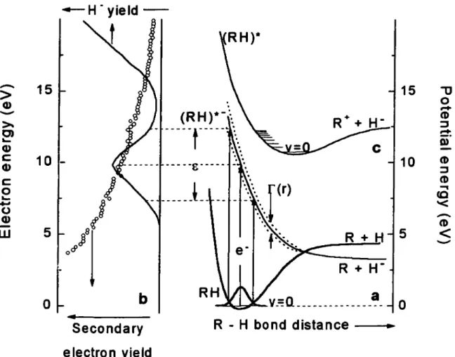
Figure 1.2. Schéma du potentiel d'énergie illustrant l'attachement d'électron resonant à une molécule RH (a). Rendement de désorption de fragments H- et représentation de la distribution d'énergie des électrons secondaires d'une particule primaire de 5-150 keV Figure 1.3 Figure 2.1 Figure 2.2 Figure 2.3 Figure 2.4 Figure 3.1 Figure 3.2 Figure 3.3 Figure 3.4 Figure 3.5 (ou proton en MeV) dans l'eau (cercles ouverts) (b). Représentation de la dissociation dipolaire d'une molécule RH (c) ... 6
Structure d'un fragment d' ADN (Faraggi et al., 1995)... 9
Vue générale de la chambre d'irradiation... 16
Structure des plaques d'Au(l 11) analysées par STM (500 nm I 500 nm)... 18
Vue générale de la chambre d'irradiation... 20
Porte échantillons... 21
Schéma du porte-échantillon et du canon à électrons... 30
Induction des bris simple, double et multiple par impact d'électrons de 500 eV d'énergie, en fonction du temps d'exposition avec un flux de 5xl012électrons/seconde et un débit de dose de 17 kGy/s... ... 36
Induction de cassures simple, double et multiple par irradiation gamma en fonction de la dose... 38
Perte de plasmides surenroulés et induction de cassures simple et double brins par impact d'électrons et par irradition gamma en fonction de la dose... 39
Dommages de I' ADN en fonction de l'énergie des électrons incidents de 100-1500 eV avec un flux de 5x10¹² electrons/seconde et une exposition de 3xl015 electrons... 41
Figure 3.8
Figure 4.1
Figure 4.2
Figure 4.3
Figure 5.1
de 500 eV d'énergie (flux de 5x10¹² électrons/seconde et
un débit de dose de 17 kGy/s) ... 43 Schéma réactionnel de la transformation des plasmides
d' ADN aux formes surenroulées (S), relaxées (R),
linéaires (L) et fragmentés (F) ... 44 Rendements de cassures doubles (A), simples (B) et perte
de plasmides surenroulés (C) en fonction de l'énergie des
électrons incidents... 66 Rendements de désorption des fragments H- induits par impact d'électrons sur des molécules condensées RH= thymine
(A), H20 (B) et tetrahydro-furfuryl alcohol (C)... 69
Perte de plasmides surenroulés (A) et induction de cassures
simple (B) et double brins (C) par impact d'électrons de 11 eV... 72 Rendements de cassures doubles (A), simples (B) et perte
de plasmides surenroulés (C) en fonction de l'énergie des
électrons incidents... 81 Figure 5.2 Induction de cassures multiples en fonction du temps
d'exposition à 50 eV... 85 Figure 6.1 Longueur d'onde de l'électron DeBroglie (en Â)
en fonction de l'énergie des électrons incidents E (en eV) ... 94
A
AD Ade ADN Au(ll l) bp 60Co Cyt DO DEA DNA DSB EBE EDTA eV F Gua L LET LEE MSB •OH 32p R Sou SC SSB STM TAE Thy Angstrom. Attachement Dissociatif. Adénine. Acide Desoxyribonucléïque. Or avec une orientation 111. Base Pair (Paire de base). Cobalt60.Cytosine.
Dipolar Dissociation (Dissociation Dipolaire).
Dissociative Electron Attachment (Attachement d'électron dissociatif). Deoxyrihonucleic Acid
Double Strand Breaks (Cassure double brin). Électrons de Basse Energie.
Ethylene diamine tetra-acetate.
Electron-Volt ( = 1.6 x 10⁻¹⁹ Joule); meV (10-3 eV); MeV (106 eV). Fragmented DNA (ADN fragmenté).
Guanine.
Linear DNA (ADN linéaire).
Linear Energy Transfer (Transfet d'énergie linéïque). Low-energy electrons (Electrons de basse énergie). Multiple Strand Breaks (Cassure de brins multiples). Radical hydroxyl.
Phosphore 32.
Relaxed DNA (ADN relaxé).
Supercoiled DNA (ADN surenroulé). Single Strand Breaks (Cassure simple brin).
Scanning Tunneling Microscopy (microscopie de balayage à effet tunnel). Tris-Acetate EDT A.
Thymine.
B. Boudaïffa
Département de Médecine Nucléaire et Radiobiologie, Faculté de Médecine, Université de Sherbrooke, Sherbrooke, Québec, Canada, JI H-5N4
Les interactions des électrons de basse énergie (EBE) représentent un élément important en sciences des radiations, particulièrement, les séquences se produisant immédiatement après l'interaction de la radiation ionisante avec le milieu biologique. Il est bien connu que lorsque ces radiations déposent leur énergie dans la cellule, elles produisent un grand nombre d'électrons secondaires (4xl04/MeV), qui sont créés le long
de la trace avec des énergies cinétiques initiales bien inférieures à 20 eV. Cependant, il n'y a jamais eu de mesures directes démontrant l'interaction de ces électrons de très basse énergie avec l'ADN, dû principalement aux difficultés expérimentales imposées par la complexité du milieu biologique.
Dans notre laboratoire, les dernières années ont été consacrées à l'étude des phénomènes fondamentaux induits par impact des EBE sur différentes molécules simples
leur phase solide. D'autres travaux effectués récemment sur des bases de l'ADN et des oligonucléotides ont montré que les EBE produisent des bris moléculaires sur les biomolécules. Ces travaux nous ont permis d'élaborer des techniques pour mettre en évidence et comprendre les interactions fondamentales des EBE avec des molécules d'intérêt biologique, afin d'atteindre notre objectif majeur d'étudier l'effet direct de ces particules sur la molécule d'ADN. Les techniques de sciences des surfaces développées et
coupures sont induites par la localisation temporaire d'un électron sur une unité moléculaire de l' ADN, ce qui engendre la formation d'un ion négatif transitoire dans un état électronique dissociatif; cette localisation est suivie d'une fragmentation.
À plus haute énergie, la dissociation dipolaire (i.e., la formation simultanée d'un ion positif et négatif) et l'ionisation jouent un rôle important dans le dommage de l' ADN.
L'ensemble de nos résultats permet d'expliquer les mécanismes de dégradation de l' ADN par les EBE et d'obtenir des sections efficaces effectives des différents types de dommages.
L
INTRODUCTION
L'utilisation des rayonnements en radiothérapie, ainsi que l'importance de la radioprotection expliquent l'intérêt croissant porté à l'étude des effets de ces agents physiques sur la matière vivante et l' ADN en particulier. En effet, l'interaction des rayons thérapeutiques (X ou Gamma) avec les cellules résulte essentiellement en la génération de l'effet Compton et de l'effet photo-électrique (électrons rapides) qui à leur tour génerent un nombre important d'électrons secondaires de basse énergie (électrons lents). Par exemple, l'absorption d'un photon de l MeV génère approximativement 4xl04 électrons secondaires, dont la plupart ont des énergies bien inférieures à l KeV (Platzman, 1955). Il a été aussi démontré par Cobut et ses collaborateurs (1998) que parmis tous les électrons secondaires éjectés dans l'eau, le long de la trace d'un électron primaire de 5 à 150 keV d'énergie initiale (ou d'un proton de quelques MeV), 50 % ont une énergie inférieure à 7.34 eV qui représente le seuil des excitations électroniques dans l'eau (Michaud et al., 1991); 56% ont une énergie inférieure à 8.76 eV qui représente un potentiel d'ionisation et 77 % ont des énergies inférieures à 20 eV (la représentation du spectre et la distribution de ces électrons sont représentées sur la figure 3(b) de l'article 3: Electron resonance in DNA induced by very low energy electrons (3 - 50 eV)). Les électrons secondaires peuvent induire donc des excitations électroniques et/ou vibrationnelles, des ionisations ou des dissociations (Sanche, 199 l, Nikjoo et Goodhead, 1991). Il serait ainsi crucial d'essayer de comprendre et de décrire les effets des radiations ionisantes par l'étude des événements et processus qu'elles déclenchent lors de leur absorption par le milieu biologique en général et par I 'ADN en particulier où sont
Ll.- Phénomènes ultra-rapides de la radiation ionisante
Pour mieux visualiser les événements fondamentaux déclenchés lors de l'absorption des radiations ionisantes, considérons l'exemple d'un système condensé composé exclusivement de molécules diatomiques AB (figure 1).
Le stade primaire comporte l'action directe de la radiation initiale. Au niveau de ce dernier, l'ionisation, la dissociation et l'excitation des molécules AB sont représentées par les réactions 1 à 6.
La majeure partie de lénergie déposée conduira à la réaction 1 produisant des ions positifs (trous) et des électrons secondaires. Ces derniers ont une énergie bien inférieure à celle de l'électron primaire et leur distribution énergétique se situe majoritairement sous le seuil des 100 eV.
Lorsque l'ion se forme dans un état dissociatif il peut conduire à la réaction 4. Le reste de l'énergie absorbée produit des molécules dans des états d'excitation rotationnelle, vibrationnelle et électronique dont certains seront dissociatifs menant ainsi à la dissociation en fragments neutres ou ioniques (réaction 5 ou 6). Bien sûr, si l'énergie de l'état excité est superieure au seuil de l'ionisation, la voie 3 devient alors probable et la molécule AB pourra suivre la voie de l'auto-ionisation. À nouveau un électron secondaire pourra être formé.
AB+Rad
Primaire
2AB+ e- (élastique)
Secondaire
A++AB
Il )JIProduits (ex.,
At+
B)
A+AB
12 )JIAi+B
Réactif
A-+AB
c
Produits (ex.,
Ai-+
B)
Détachement d'e- (ex.,
Ai+
B + e·)
14Figure 1.1. : Événements produits lors du transfert d'énergie de la radiation ionisante à la molécule AB.
l'une des réactions 1-6. Cependant, l'amplitude de probabilité de chacune de ces réactions produites par des électrons secondaires est considérablement différente de celle due aux électrons primaires car la nature ondulatoire de l'électron ne peut être ignorée à basse énergie. L'électron lent perturbe d'une façon marquée les nuages électroniques des molécules avoisinantes. Il peut s'attacher temporairement à une molécule et lui céder une partie importante de son énergie. Ce phénomène appelé "résonance" électronique joue un rôle déterminant dans la compréhension de la déposition d'énergie dans le milieu. En effet, lors de l'interaction résonante, l'électron réside plus longtemps dans le voisinage de la molécule, induit généralement une plus grande distorsion des orbitales moléculaires et un échange d'énergie plus important, comparativement à l'interaction non résonante. Cette perturbation peut engendrer des excitations vibrationnelles ou électroniques (9) et l'attachement dissociatif (10). Dans la matière condensée, à l'énergie de la résonance, ces derniers phénomènes dominent souvent tous les autres causés par des électrons lents. Le temps de vie des ions transitoires ainsi formés se situant généralement entre l ff 12 à l 0-15 s, on les considère par ailleurs, comme faisant partie des phénomènes plus rapides que la picoseconde.
Une représentation pratique pour visualiser une résonance est de décrire l'énergie potentielle de la molécule en fonction des distances intemucléaires.
La représentation est encore plus simple pour une molécule diatomique où une courbe de potentiel à deux dimensions illustre adiquatement l'énergie potentielle de la molécule neutre, de ses états électroniques et de ses ions négatifs figure 1.2 ..
En effet, une molécule condensée à basse température est normalement dans son état électronique fondamental et dans son état vibrationnel le plus bas.
La formation d'une résonance est illustrée par le passage de la courbe de potentiel de la molécule neutre à une courbe d'ion négatif dans un temps très court de sorte que la distance intemucléaire demeure pratiquement inchangée, c.à.d., la transition s'effectue dans la région du Franck Condon.
L'anion évolue ensuite selon sa nouvelle courbe de potentiel, souvent répulsive dans la région du Frank Condon. Par exemple, la molécule pourra voir ses deux atomes s'éloigner l'un de l'autre. L'autodétachement de l'électron laisse alors la molécule dans un état électroniquement et/ou vibrationnellement excité. Par ailleurs, si le temps de vie de la résonance est assez long pour franchir le point de croisement entre la courbe de l'ion négatif et celle de l'état fondamental de la molécule neutre, la dissociation devient alors, le canal de décroissance possible. Un ou des fragments neutres et un fragment chargé négativement sont formés et on parle alors d'attachement dissociatif (AD).
-
>
15
15-u
Q)-
0-
CD >- ::::J O> !:!:...
m Q)c
10 - 10 CD Q) ::::Jc
l
CD 0....
...cc
-
0,u
'< -Q) CDw
5 o&Jl
R+H
5
-
<
al
R +
H-b
0
Secondary
R - H bond distance
electron yield
Figure 2.1. : schematic potential energy diagram illustrating resonant electron attachment to a molecule RH (a). Anion fragment yield and calculated relative secondary-electron energy-distributions (b). Dipolar dissociation (c).
Le troisième groupe de la figure 1 (11-14) met en jeu des anions, cations et radicaux neutres créés par des processus dits dissociatifs. Ces radicaux possèdent une énergie cinétique de quelques eV et peuvent réagir rapidement avec le milieu.
On sait par ailleurs que le libre parcours moyen de la majorité des électrons lents varie de 1 à 1
ooA,
ils ont donc le potentiel de produire des dommages localisés dans I' ADN, qui a un diamètre de 20A,
et lorsqu'autour du nucléosome a un diamètre 100A.
Il est bien connu aussi que les dommages "localisés" sont les plus difficilement réparables et les plus létaux. Or la plupart des études précédentes ont caractérisé le dommage de l'ADN résultant d'électrons de haute énergie (KeV à MeV), ou d'électrons thermalisés et solvatés, d'ions ou encore de radicaux distribués le long de la trace des radiations et des spurs. En effet, très peu d'études ont été consacrées aux mesures des dommages de I 'ADN induits par des électrons secondaires de basse énergie ( < Ke V). Même si ces investigations peuvent être techniquement difficiles, elles permettent néanmoins de mesurer directement les interactions des électrons secondaires de basse énergie avec l'ADN, qui est l'étape cruciale pour la compréhension de l'effet biologique des radiations ionisantes.L2. ADN: Cible principale des rayonnements ionisants
1.2.1. Structure de /'ADN
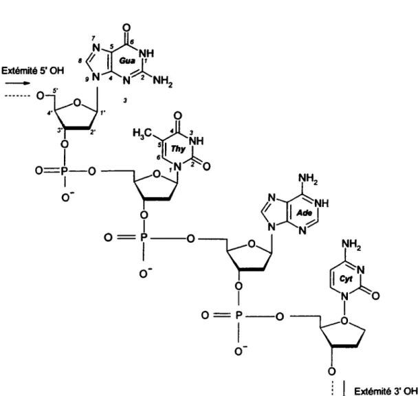
La molécule d'ADN est un polymère formé de deux brins oligonucléotidiques antiparallèles enroulés hélicoïdalement l'un autour de l'autre (double hélice). Chaque brin est campos~ d'une succession de quatre nucléosides. Un nucléoside est formé par l'une
3' et le carbone 5' du nucléoside voisin {Figure 2). L'ordre dans lequel sont disposées les sous-unités constitue le code génétique.
Figure 1.3.: Structure d'un fragment d'ADN (Faraggi et al., 1995)
molécule, chaque brin servant de matrice pour la synthèse du brin opposé. Dans la double hélice, les plans de chacune des bases sont parallèles entre eux et perpendiculaires à l'axe de l'hélice.
A cette structure, s'ajoute une première couche d'hydratation constituée en moyenne de 12 à 15 molécules d'eau associées à chaque nucléotide (formé par l'union d'une base avec un 2'-déoxyribose lui même attaché à un groupement phosphate) (Swarts et al, 1992). Ces molécules d'eau, fortement liées à l'ADN, accroissent la stabilité de l'ensemble.
Les modifications de la structure chimique des bases nucléiques peuvent conduire à des processus de mutation, de cancérisation et de létalité cellulaire. Ceci a pour conséquence d'altérer le message génétique, rendant, par exemple, inactive la protéine dont la synthèse est dirigée par le gène endommagé. Si la lésion a pour effet de bloquer la réplication de l'ADN, elle peut entraîner la mort de la cellule.
En ce qui concerne les ruptures des chaînes d'ADN (cassures simples et doubles), des fragments formés peuvent être déplacés, par exemple, d'un chromosome à l'autre (une telle réorganisation est appelée recombinaison génétique). Ces fragmentations sont responsables d'aberrations chromosomiques, en général très défavorables à la vie de la cellule car elles se traduisent souvent par une perte de l'information génétique portée par les chromosomes ou par de mauvaises interprétations de cette mémoire génétique.
Parce qu'ils modifient les gènes des cellules, les rayonnements ionisants sont qualifiés de
génotoxiques.
Dans ce travail, nous nous sommes concentrés seulement sur l'étude des cassures de brins simple, double et multiples.
L2.2. Évolution des événements après irradiation
La succession des événements physiques, chimiques, biochimiques et biologiques intervenant après l'ionisation primaire de l'ADN est présentée dans le tableau l pour les trois cas : effets direct, quasi-direct et indirect (Becker et Sevilla, 1993 et de Faraggi et ses collaborateurs, 1995).
10-18 - 10-13 de l'ADN, donnant du milieu proche de l'eau non liées à 1' ADN, ADW0
, e-scc et ADN•. I' ADN {eau, complexes donnant HiO+-, e-scc et
ADN/protéines), donnant Hio·.
Hio+·, protéines+·, e-sec. HiO • et protéine•.
Thermalisation des Transfert d'une partie des Formation des radicaux électrons. Migration des charges {e-sec et ''trous") libres de l'eau ("OH,
H°
et e-10-13 - 10-10 charges {électron et formées vers l' ADN, suivi aq). Diffusion de ces espèces''trou") et piégeage de de processus analogues à et réactions d'une partie de celles-ci dans des sites ceux produits par l'effet celles-ci avec l'ADN. radicalaires dans I' ADN. direct. Formation de sites Formation de sites
radicalaires dans l' ADN. radicalaires dans l' ADN. Protonation et déprotonation réversibles donnant des radicaux neutres (ADN) ; 10-10 - 10-J addition des ions OH- {ou H20) avec les cations radicaux; formation des pontages ADN-protéines, ADN-ADN ; autres modifications chimiques... Il faut noter que différents effets peuvent conduire à des modifications chimiques identiques.
10-3 - 103 Evolution des radicaux des fragments osidiques conduisant aux cassures doubles de chaînes d'ADN. Réparation enzymatique des dommages.
103 - 1010 Effets sur le développement cellulaire et la réplication. Les cassures doubles de chaînes peuvent provoquer la mort cellulaire, les modifications de bases -mutagénèse, létalité cellulaire ou cancérogénèse.
Tableau l : Evénements produits par l'action du rayonnement ionisant sur l'ADN cellulaire. D'après Becker et Sevilla (1993).
L3.- Vue d'e11semble
Les études antérieures dans notre laboratoire ont caractérisé les interactions des électrons secondaires avec des molécules simples (ex., Ni, CO, 02, H20, NO, C6H6) et complexes {ex., les hydrocarbones linéaires et cycliques, allant des bases del' ADN, des
oligonucléotides au plasmides d' AND surenroulé en phase condensée). Il a été possible d'étudier ces interactions en permettant à un faisceau d'électrons de basse énergie de percuter une cible sous des conditions d'hyper-vide. Ces investigations ont démontré que l'impact des électrons de basse énergie peut conduire à des dissociations en fragments moléculaires, atomiques et radicalaires.
Ces études nous ont permis de développer deux nouveaux montages et de nouvelles méthodes pour étudier le dommage, induit par les électrons lents, à I' ADN irradié sous des conditions d'hyper-vide. Nous avons, en premier lieu, étudié l'effet des électrons à des énergies comprises entre 100 et 1500 eV, et pour ce faire, nous avons mis au point un évaporateur d'or afin de fabriquer nous mêmes les surfaces (figure 2.2) sur lesquelles on dépose les cibles d' ADN à irradier. Nous présentons dans l'article n°1 (Induction of single and double strand breaks in plasmid DNA by 100 to 1500 eV) les dommages (assures simple double et multiple) induits par les électrons de 100 à 1500 eV. Une comparaison de ces résultats et ceux obtenus par irradiation
y
est aussi présentée. Nous abordons également les problèmes liés au calcul de la dose dans le cas des électrons de basse énergie.Suite à de nombreux problèmes techniques reliés à la préparation des échantillons et au mauvais contrôle du faisceau d'électrons comme mentionné dans l'article n°l, nous avons mis au point un deuxième montage et de nouvelles techniques de préparation des cibles et de traitement des dommages induits à l' ADN, avec un meilleur contrôle du faisceau d'électrons. Les résultats obtenus avec ce dernier montage ont donné lieu à trois articles. Nous présentons dans le premier article (Resonant fonnation of DNA strand breaks by low energy (3 - 20 eV) electrons), les rendements de bris simple et double brins mesurés
d'électrons d'énergie comprises entre 3 et 100 eV.
H.
SYSTÈMES EXPÉRIMENTAUX
D.1.-
Description du 1er montage expérimental
ILJ.J.- Description générale de la procédure
Dans un système à hyper-vide (Fig. 2.1 ), des échantillons d' ADN sec déposés sur un substrat métallique sont bombardés par un faisceau d'électrons d'intensité et d'énergie variables. Ensuite les échantillons sont retirés du système à vide et analysées par électrophorèse.
Les EBE sont faciles à produire, cependant, la pénétration et la portée limitées de ces particules nécessitent une préparation très stringente des cibles. Il faudrait, en premier lieu, avoir un film mince d' ADN sec, car les molécules se trouvant en profondeur dans un film trop épais peuvent être complètement protégées (Hutchinson, 1954). En second lieu, l' ADN doit être étalé sur une surface conductrice pour pouvoir déterminer le potentiel et l'énergie des électrons incidents et de permettre aux électrons de percuter la cible d' ADN avec une énergie précise. Notre choix pour la surface a été porté sur l'or qui est un métal inerte à 99.9 % de pureté.
250 Ils Turbo
- molecular Drag Pump
Sealed Dry Nz Glove Box with
2 Opposite Pairs (not shown for clarity)
Rotatable Sample Holder Wheel with Faraday Detector on l O"CF in Retracted;lN Vented) Position
0 -ring Sealed Access Door
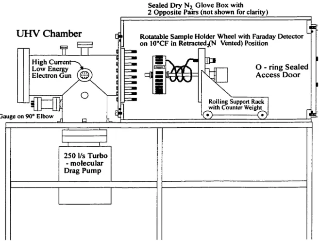
Figure 2.1. : Vue générale de la chambre d'irradiation1•
1 Pour plus de détail, une vue intérieure de la chambre d'ultra-vide est représentés dans la figure 3.1.
11.1.2.- Évaporateur d'or
L'évaporation de l'or s'effectue sur des plaques de verre, dans une cloche à vide (-10-8 Torr) et les plaques peuvent être chauffées pour une meilleure qualité de déposition. Cette chambre à vide permet la production de 60 - 70 plaques d' Au (300 cm2) dans les mêmes conditions.
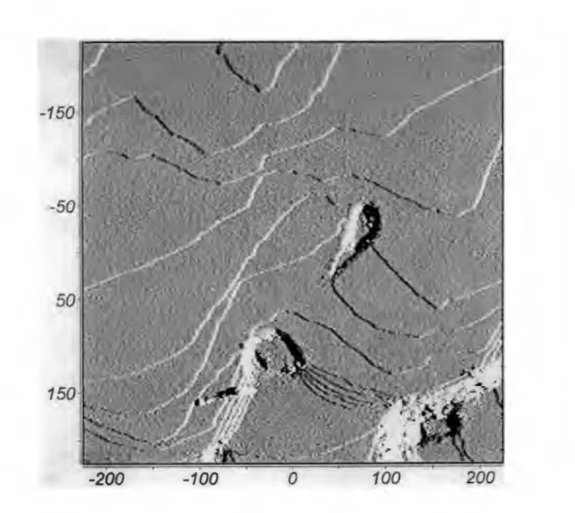
Les plaques de verre chimiquement nettoyées sont placées dans l'évaporateur, après pompage, les plaques sont chauffées pendant 15-20 heures avant l'évaporation de I' Au. La qualité et la structure des plaques d'or sont vérifiées par microscopie de balayage à effet tunnel ("scanning tunneling microscopy"). Ceci donne de larges plans de surfaces (quelques 100 nm), d'orientation (111), avec des échelles atomiques bien visibles (Fig 2.2).
Afin, d'éliminer les contaminations organiques résiduelles, les plaques sont copieusement lavées avec de leau distillée et déionisée.
-160
-50
50
-200
-100
0
100
200
Figure 2.2. : Structure des plaques d' Au (111) analysées par STM (500 nm / 500 nm).
11.2.-
Description du 2ème montage expérimental
Nous avons mis au point un deuxième montage pour faciliter la préparation des échantillons dans une atmosphère contrôlée d'azote sec. La surface utilisée dans ce cas est le Tantal. Ce choix a été fait après plusieurs essais de surfaces ordonnées, telles que, l'or, le platine, le molubdène (MoS2), le tungstène, ... etc. En effet, nous avons obtenu de meilleurs résultats et une meilleure reproductibilité avec le Tantal.
11.2.1.- Chambre d'irradiation
Le montage (Fig. 2.3) se divise essentiellement comme suit :
- Une chambre hermétiquement fermée sous atmosphère contrôlée d'azote sec, dans laquelle s'effectue la préparation et la lyophilisation des échantillons. Cette chambre est reliée à un système à vide, muni d'une pompe turbomoléculaire raccordée à une pompe à vide primaire. La pression typique dans cette partie de l'appareil est d'environ 10·10 Torr.
- Un canon
à
haut courant (0-50 µA), de basse énergie (0 - l OO eV) constitué d'un filament de tungstène thorié comme source d'électrons, de lentilles pour former et focaliser le faisceau d'électrons. Le faisceau d'électrons orienté par un champs magnétique, quitte le monochromateur (D) pour percuter lefilm
condensé sur la cible (L).N A
•
TOPVIEW G A 0Figure 2.3. : Vue générale de la chambre d'irradiation. A: Pompe turbo-moléculaire (520
Vs); B: Jauge ionique; C: Boite à gants fermée hermétiquement; D: Canon d'électrons; E: Sonde Kelvin; F: Fenêtre; G: Analyseur de gaz résiduel (RGA); H: Fenêtre; I: Porte d'accès; J: soufflet Anti-vibration; K: Commande de rotation; L: Porte échantillons; M: Alimentations électriques; N: Commande linéaire; 0: Fenêtre.
- Un porte échantillons sur lequel sont placées les cibles devant être bombardées (fig. 2.4).
- Une cage de Faraday muni d'une fente de 0.33mm permet de mesurer la densité et la distribution spatiale du faisceau d'électrons. Des plaques phosphorescentes ont été aussi utilisées afin de visualiser et de contrôler la distribution des électrons sur les cibles d'ADN.
Le nombre d'électrons percutant l'échantillon par unité de temps est calculé à partir de la fraction du courant total incident qui atteint le dépôt
B
Figure 2.4. : Porte échantillons. A: Support à échantillons avec feuille de Tantal, B: Porte échantillons fixé sur un plateau horizontal tournant.
Phosphore qui fluorescent lors de l'interaction de cette dernière avec les électrons. Ceci nous pennet ainsi d'orienter le faisceau d'électrons, grâce au champs magnétique, et de l'étaler, grâce aux lentilles, afln d'obtenir une surface de bombardement recouvrant toute la surface de I' ADN déposé.
Avant d'introduire les cibles, la chambre UHV incluant le porte échantillons peut être dégasée à 100°C.
llLJ.
ARTICLE N °1 : Induction of single and double strand breaks
in plasmid DNA by 100 to 1500 eV electrons.
In
press.
!nt.
J.
Rad.
Bio/. 2000.
Sanche
Canadian Medical Researcb Council Group in the Radiation Sciences, Dept. of Nuclear Medicine and Radiobiology, Faculty of Medicine, University of Sherbrooke,
Québec, Canada JI H SN4
ABSTRACT
Dry supercoiled plasmid DNA was irradiated with electrons of energies ranging from 0.1 to 1.5 keV and the results were compared with those obtained by y-irradiation of the same plasmid in solution. For electron irradiation, the plasmid is deposited on a gold substrate under a controlled atmosphere to minimize contamination of the DNA film. Electron bombardments are performed under ultra high vacuum (UHV - 10·9 Torr) conditions. DNA damage is detected by gel electrophoresis followed by quantitation of the DNA bands by fluorescence or by hybridization with a radioactive probe. Our results show that electrons within the energy range of the secondary electrons generated by high-energy ionizing radiation induce single, double and multiple double strand breaks in DNA. For equal doses, we observe a marked increase in the efficiency of induction of double and multiple strand breaks in supercoiled DNA as a function of electron energy. In contrast to y-irradiation, the formation of small DNA fragments by electrons does not seem to be related to the production of the linear form of the plasmid. We also discuss problems associated with low-energy electron irradiation experiments and dose calculations in thin films.
The interaction of diagnostic and therapeutic x-rays or gamma rays with cells results essentially in the generation of Compton recoil and photo-electrons (fast electrons) which in tum generate large numbers of low energy electrons (slow electrons) (Uehara and Nikjoo, 1996). For example, the absorption of a l MeV photon generates approximately 4x 10⁴ secondary electrons, most of which having energies well below 1
keV (Platzman 1955). These electrons may induce electronic and/or vibrational excitations, ionizations or dissociations (Sanche, 1991, Nikjoo and Goodhead, 1991 ). Subsequent chemical reactions result in the DNA damage characteristic of ionizing photons, such as single and double strand breaks (von Sonntag, 1987), and oxidative damage to the bases (Fuciarelli et al. 1990), resulting mainly from hydroxyl radical
formation (Miliigan et al. 1993). Since the inelastic mean free path of the majority of
secondary electrons varies from l to 100
A
(Marsolais et al. 1991; Pimblott and La Verne1995; Bass and Sanche 1998), they have a high probability of depositing energy in clusters, producing complex damage in DNA (Nikjoo and Goodhead, 1989; Goodhead, 1990), which may be responsible for a major part of the biological effectiveness of low-LET radiation (Goodhead and Nikjoo, 1990). lt is believed that clustered DNA damage is the most difficult to repair and thus the most lethal (Ward 1981, 1985). Most previous studies have characterized the DNA damage resulting from either high-energy electrons, with energies in the keV to MeV range, or thennalized and solvated electrons, and thermal ions and radicals distributed along the radiation tracks and spurs. However, very few studies have endeavoured to measure the DNA damage which can be induced by low energy secondary electrons, in the sub-keV energy range (Folkard et al., 1993). Although
these investigations may be technically demanding, they should allow us to directly
from 1 eV to 1 keV {Hutchinson, 1954; Cole, 1974; Folkard et al. 1993; Dugal et al. 1999). Previous studies have characterized such damage for simple (e.g. N2, CO, 02, H20, NO; Kimmel et al, 1995; Sanche 1997, Bass et al. 1998) and more complex molecules;
e.g., linear and cyclic hydrocarbons (K.elber and Knotek, 1982; Rowntree et al. 199la,
1991b) as well as DNA bases (Huels et al. 1998) and small single stranded
oligonucleotides (Dugal et al. 1999) in the condensed phase. These investigations have
demonstrated that low energy electron (LEE) impact can lead to molecular dissociation, i.e. to the production of atomic and radical ions and fragments.
LEE experiments on insulating materials ( e.g., biological, organic and molecular solids) must usually be performed with thin films condensed or deposited on a metal substrate in order to avoid charging of the target (Sanche 1997). Since LEE have short mean free paths (Tougaard and Chorkendorff, 1987), it is also necessary to minimize surface contamination during the experiment. In other words, the prepared surface must be atomically clean and kept clean, before and during the measurements. This is usually accomplished by introducing the sample in the vapor phase, into an ultra-high vacuum (UHV) system, and allowing the target molecules to condense on a clean metal substrate. Afterwards, the induced damage is monitored in vacuo by techniques of microanalysis such that the sample is never exposed to atmospheric contaminants. UHV techniques of microanalysis such as electron stimulated desorption, temperature-programmed
spectroscopies are highly sensitive and therefore it is possible to monitor LEE-induced damage with very small amounts of material; e.g., by analyzing an area of a few mm2 on
films having thicknesses ranging from 1 to about 5 nm. Thus, due to the high
conductivity of the metal substrate and the small film thickness, the molecular solid target does not charge appreciably during the time required to measure the induced damage. Under these conditions, the electron energy remains well defined within the beam resolution.
Unfortunately, large biomolecules usually cannot be vaporized without decomposition. Furthermore, when the probed damage cannot be assessed under UHV conditions, the sample must then be both prepared and analyzed outside the UHV environment. Since ex vacuo techniques are usually less sensitive, more degraded
material must be prepared by electron bombardment, a condition which may be difficult to meet for thin films and highly focused LEE beams. Thus, new methods of analysis must be devised if we are to perform such experiments with an accuracy and reliability similar to those performed in vacuum on thin condensed films. We are presently developing this type of technology for measurement of LEE-induced damage within pure samples prepared and analyzed outside UHV.
The analysis of single and double strand breaks induced by LEE impact on DNA represents a typical experiment, in which both target preparation and analysis must be performed outside an UHV environment. In this article, we describe our first attempt to develop an apparatus and the methodology to determine the damage induced by LEE in supercoiled plasmid DNA, irradiated under UHV conditions. As in the case of simpler molecules, we require that the target be clean (i.e., pure) and thin. In order to insure
present study, we show that secondary electrons of energies from O. l to 1.5 keV induce single, double, and multiple double strand breaks in supercoiled plasmid DNA. In addition, y-rays were used as a positive control to generate strand breaks in the same plasmid, thus allowing a comparison of the formation and interconversion of the three topological forms of the plasmid. Finally, our results are compared with published results obtained with soft X-rays, y-rays and 25-4000 eV electrons on similar targets irradiated under different conditions. This study has allowed us to better define the problems associated with LEE irradiation of high molecular weight nucleic acids; namely, difficulties associated with the stability of pure supercoiled plasmid DNA in UHV, the relatively small amount of material which can be irradiated and the dosimetry associated with LEE irradiation ofthin films.
MATERIALS AND METHODS
A. Preparation of supercoi/ed plasmid DNA and metal substrate
We use gold as substrate films since they are relatively inert and easy to prepare by evaporation onto glass or mica. High-purity gold (99.99 %) is evaporated onto either freshly cleaved mica or glass slides, degassed at 350° C or 150° C, respectively, in an UHV chamoer held at 10"8 Torr. The quality of the gold substrates is verified by scanning
tunneling microscopy. The substrate gold surfaces consist of azimuthally disordered large surface planes (several hundred nanometers) of crystalline Au(l 11).
coli (DH5a) and extracted by alkaline lysis. The supercoiled form of the plasmid is purified using an anion exchange resin (Qiagen), following the manufacturer's protocol. The plasmid is precipitated and re-dissolved in nano-pure water and stored frozen.
B. Preparation of DNA onto gold substrates
Ali sample manipulations are carried out in a hennetically sealed glove box under a dry nitrogen atmosphere. This glove box is attached and sealed directly to the UHV chamber to allow sample transfer without exposure to air. The Au substrates are cooled to -800 C and 25 µI of DNA solution in ultra-pure water containing 500 ng of plasmid are deposited, covering an area of about 25 mm2• The DNA is then lyophilized using a hydrocarbon-free sorption pump. The thickness of the DNA is estimated to be about 10 nm (density of DNA of about l.35 g.cm-3) assuming minimal (less than 20 %) clustering of the plasmids in the solid. Although we have not experimentally confirmed the conformations of the DNA molecules in our target solids, electron microscopy studies have shown that supercoiled plasmids adopt a plectonemic form when deposited on carbon grids (Cozzarelli et al. 1990; Vologodskii 1992). ln plectonemic supercoiled plasmids (i.e. inter-wound DNA as opposed to solenoidal or toroïdal DNA) the DNA winds up and back down a super-helical axis, thus creating many sites where the DNA helix crosses itself or is in close proximity to another part of the same DNA molecule. Thus the IO nm thick solid is estimated to consist on average of about 5 layers of plasmid DNA.
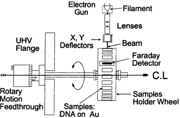
The samples are fixed to the rotary wheel shown in figure 1 and introduced into an UHV chamber previously degassed by heating to l 000 C under vacuum for 3-4 days. Afterwards, the UHV chamber is evacuated for ca. 24 hours by a hydrocarbon-free
UHV
FI ange
Rotary
Motion
Feedthrough
Electron
Gun
X,
y
-~
Deflectors
Filament
Lenses
Bearn
Faraday
Detector
C.L
1--Samples
Samples:
...__..._.
Helder Wheel
DNAon Au
Figure 1: View of rotatable sample holder and low energy electron gun.
C. LEE and }"ray i"adiation.
The UHV chamber is equipped with a high current (0-50 µA, 0.5 eV resolution) electron source, covering the energy range of 100-1500 eV. The incident electron beam is collimated with a coaxial magnetic field; as shown in Figure 1, electric fields in the x and
y direction are applied to the electron beam for scanning the beam across the sample. In the present experiments, the beam was scanned at a frequency of 100 Hz over an area much larger than that covered by the DNA sample, in order to ensure that all the DNA was irradiated. The number of electrons incident on the target DNA was determined from the area scanned by the beam and the area occupied by the DNA. DNA damage by LEE can be expressed as a function of the exposure, &, the total number of electrons which have arrived at the target solid of area A (5 mm diameter on average) after a fixed time t of irradiation; thus & = JtA, where J is the flux-density (number of electrons s-1 cm-2). The details of the rotatable sample holder are shown in Figure 1. One position on the holder is occupied by a Faraday detector slit (0.33 mm by 5 mm) which allows measurements of the spatial distribution of the electron beam. Irradiation times with a beam current of 1 µA were varied between 10 and 90 min. In order to generate positive control samples containing single, double and multiple double strand breaks, plasmid DNA samples in solution are exposed to a graded series of doses of ionizing radiation in a 60Co y-ray source
(Gammacell 220 irradiator, Nordion Inc., Canada).
D. Determination of DNA damage and dosimetry
Following electron irradiation, the samples are re-dissolved in Tris-EDT A buffer (pH 7 .5). Theo samples which have been y-irradiated or electron bombarded are electrophoresed on a 1 % agarose gel in T AE running buffer. The gel is soaked in a
et al. (1982). The
radioactivity is then quantified using a Phosphorlmager (Molecular Dynamics). Several types of DNA controls are produced, including DNA in solution (prior to lyophilisation), lyophilized DNA held in dry Ni and lyophilized DNA held under UHV, but not irradiated with electrons. The electron beam results are expressed in terms of DNA damage as a function of electron energy and dose or time of electron irradiation at a given electron current, i.e., exposure. In ail cases, the dose rate is provided in the figure captions such that time can be converted to dose. Finally, aliquots of solution of y-irradiated samples are analyzed in the same manner and the results are expressed as a function of dose.
The damage induced by LEE on thin films is usually measured in terms of the number of specific fragments or breaks per incident electron or similar units, such as an effective cross section for a given target (Leclerc et al, 1987; Sanche 1995). Although such definitions provide values which are significant for beam experiments on thin targets, they do not allow easy comparison with the results of other experiments which are expressed per unit of absorbed energy (or dose) by the target. ldeally, one would like to be able to calculate from available cross sections and stopping powers the energy absorbed by the thin film during the time of bombardment. However, such calculations are bound to provide unrealistic values, since the deposited energy from the portion of the incident electron beam which interact with the film constituents is not retained within the
film.
It is known, for thin films ( 1-5 nm) on metal substrates, that within picoseconds most of thetransferred to the metal substrate via exciton motion followed by quenching on the metal (Zimmerer, 1988) and coupling of intramolecular vibrations to phonon modes of the substrate (Cavanagh, 1994). Furthennore, part of the incident electron energy is directly deposited in the metal substrate via image-charge interactions (Gomer, 1975) and most of the prompt photons from decay of excited states are emitted in vacuum and in the substrate.
To demonstrate this point, we can calculate, based on the thin film approximation, the rate of energy deposition in the first DNA layer of our film. For a thin target of thickness l'.ll, bombarded by an electron current of intensity Io, during time t, with an energy E, the total amount of energy absorbed by the target, L\ W(E), may be written as the sum of the energies absorbed
&w(E,Ep)
by each process Ieading to an energy loss Ep while the beam traverses the target.i.e.
&W(E)=
Î&w(E,EP)
[l]p=O
where [2]
where Q is the scattering probability per unit length. Substituting [2] into [ l ], we obtain,
[3]
n
in which the stopping cross section S(E) = LQ(E,EP)EP related to the stopping p=O
powers by a density factor (Kimura et al., 1993). Within a first approximation, we assume that this thin layer approximation is valid for energy deposition within a first layer of DNA (i.e., through a diameter of -20 A). ln this case, the instantaneous energy 33
electron energy, a dose rate of about 17 kGy/s to the first layer. This means that for irradiation times typical ofthose of the present experiment (e.g., IO min), the first layer of DNA would have received about l 07 Grays. Assuming that ail this energy remains in the film, we cm calculate the effective temperature at long times from Debye's model of specific heat (Ashcroft and Mermin, 1976). Taking tabulated values of Debye's temperatures and specific heats from the latter reference, we find an unrealistic value of the order of 105 degrees Kelvin for the effective temperature of the first layer. Even ifwe assumed that the entire film would absorba hundred limes Jess energy per unit mass, it would have decomposed and evaporated during the experiment.
Another problem in assigning a dose only to the DNA sample anses from secondary electrons created in the metal substrate which retum to the thin film, where they may cause damage. Obviously, the film cannot simply be considered in isolation since, in these experiments, energy is imparted to the film-substrate system, which is the effective target. A more realistic dose calculation should therefore include the portion of the substrate which has received energy from the beam. This is also difficult to estimate, but as a first approximation, we can assume that beam energy is deposited within the extrapolated ranges of the electrons in the substrate-film system. Since energy quickly flows out of the extrapolated range, this approximation also overestimates the dose delivered to the substrate-film system but it is more comparable to that measured in
in the work of Iskef et al. (1983), we fmd that the present results were obtained at a dose rate of about 50 Gy/s at 500 eV. This means, for example, that for a 10 min irradiation at 500 eV a dose of 30 kGy bas been delivered to the target. According to this estimate, we must therefore consider that the present LEE-results were obtained at high doses. With the present apparatus and methodology, the use of considerably smaller doses resulted in amounts of measured fonns of DNA which were within the statistical fluctuations of the control samples; i.e., those which were transferred into UHV but not irradiated. We also note that within this calculation of energy absorbed by the substrate-DNA system, the absorbed dose becomes dependent on extrapolated electron ranges which are themselves inversely proportional to the stopping powers.
~ 70 c: ~ 60 (/)
E
J2
50 <(z
40 0...
c: ~ 30~
"O.._
20 0 "O 10 Q)>=
a--Solution contrai 0 min 10min 20min 30min
Time of irradiation (min)
Relaxed
c::J
Linear - SupercoiledD
Fragmented60min 90min
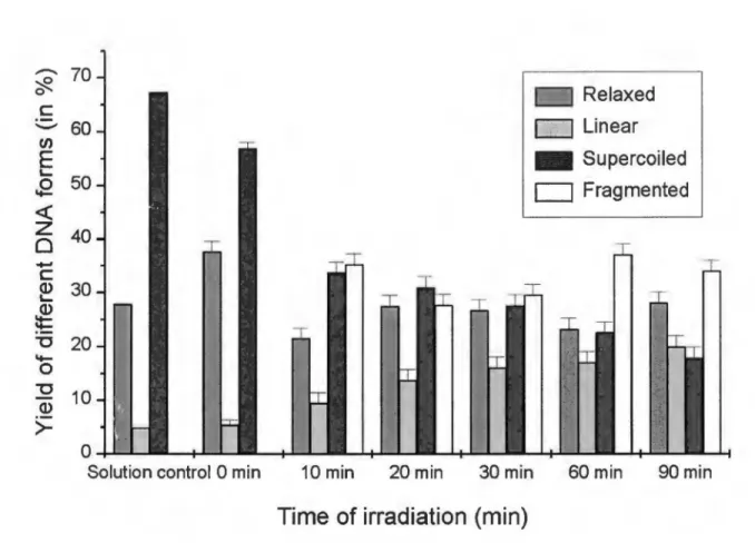
Figure 2: Induction of single, double and multiple double strand breaks in plasmid DNA by a beam of 500 eV electrons as a function of irradiation time (i.e. exposure) for a flux-density of about 5x10¹² electrons/second and dose rate of about 17 kGy/s.
RESULTS
The induction of DNA damage by 500 eV electrons as a function of irradiation time (i.e. exposure) is shown in Figure 2. Each point represents an average of five independent measurements. The error bars correspond to the spread in the data. The plasmid (pGEM3Zt{-)) in solution, prior to deposition on the gold substrate, consists of approximately 70% supercoiled (S) molecules, less than 5% linear (L) and about 25% relaxed circular (R) molecules (Figure 2; solution control). Deposition, lyophilization and re-dissolution of the plasmid results in the induction of some further single strand breaks (SSB) but no double strand breaks (DSB) (Figure 2; 0 min irradiation). Irradiation of the lyophilized plasmid under UHV with 500 eV electrons (flux-density of about 5xl012 electrons/second-cm2) leads to further loss of the supercoiled form and to the formation of three forms of the plasmid: relaxed circular, full length linear and short linear fragments, resulting from the generation of single strand breaks, double strand breaks and multiple double strand breaks, respectively. The short linear plasmid fragments appear as a smear following agarose gel electrophoresis indicating that they are of random lengths. Within experimental error, the amount of linear plasmid increases linearly with irradiation time up to 30 min, while the amount of supercoiled plasmid decreases.
For comparison, the induction of strand breaks in an aqueous solution of plasmid as a function of dose of y rays is shown in Figure 3. Each point corresponds to three independent measurements. The error bars represent the spread in these data. Under y-ray irradiation, both the relaxed and linear forms of the plasmid increase as a fonction of radiation dose, while the supercoiled form decreases. As observed with 500 eV electrons irradiation,
y
irradiation also induces formation of short linear DNA fragments (i.e. multiple double strand breaks) but only at the highest doses, (Figure 3; 300 Gy). The short 37from Fig. 2) and in Fig. 4(d-f) for y-rays (tak:en from Fig. 3).
-
RelaxedCJ
Linear ~ 0c
(/)E
!....J2
<(z
0
...
c
~
~
'Ulot-o
'U Q) >-90 80 70 60 50 40 30 20 10 0ml
SupercoiledCJ
Fragmented Solution control 5 Gy 10 Gy 20 Gy 40 Gy 80 Gy 160 Gy 300 GyDose in Gy
Figure 3: Induction of single, double and multiple double strand breaks in plasmid DNA by gamma rays as a function of dose.
1.0
0.6
j Supercoiled 1\
ISupercoiled 1 c(•
z
0.5
Cl
0.4
'' ~ 0 (d) Uj0.2
E
'-0.0
!Relaxed 1 jRelaxed 1a
0.6
0.4
(J
!•
...
c
i0.4
e
i j j~
0.2
i j0.2
'lJ (b) (e)0.0
~0.0
0 1 Linearl ILinearlc
0.3
0.4
0u
0.2
:!
f!
/
0.2
LL0.1
(c) (f)0.0
0.0
0 100 200
300400 500
0
501 OO 150 200 250 300
Low-energy electron
y-Rays irradiation
irradiation (Dose in kGy)
(Dose in Gy)
Figure 4: Loss of supercoiled and induction of single and double and breaks in plasmid DNA by low-energy electron and gamma rays irradiation as a function of dose.
electrons). The dose rates calculated from corresponding extrapolated ranges appear in the scale on top. The results indicate that for equal exposures, the efficiency of forming multiple double strand breaks increases as a function of incident electron energy. For example, 100 eV electrons converted approximately 10% of the DNA to short linear fragments white an equal exposure to 1500 eV electrons converted approximately 50% of the DNA to short linear fragments. When strand breaks are expressed in terms of yield per adsorbed dose this increase is even more significant and the linear form is clearly found to increase with electron energy, white the relaxed configuration remains constant. This is shown in Fig. 6, where the percentage of the different forms present after irradiation have been normalized to the 500-eV dose and plotted as a function of electron energy.
The relationship between the loss of supercoiled DNA (S(D)) and the exposure is shown in Fig. 7, for the data on 500 eV electrons taken from Fig. 2. Since, at a fixed energy, the absorbed energy dose is proportional to the exposure, one can see from Fig. 7 that the loss of supercoiled plasmid in thin films can be defined by the typical dose-response relation:
S(D) = So exp(-D/Do)
where, D represents the dose, 00 a constant expressed in dose units and So the initial percentage of supercoiled DNA in the unirradiated sample.
Dose (in Gy/s)
Solution control 0 123 104.5 104.5 70.41 62.6890 --~--~---~..-~---~--~---~--~--~--~--~---.
-'#.
80c:
'='
en
70E
~ 60s
~
500
... 40c:
~ ~ 30 "'C I+- 20 0 "'C Q)>-
10 0 Solution control 0 eVT
Relaxed1==:J
Linear - Supercoiled ~ Fragmented..___ ____
__,T
1 OO eV 250 eV 500 eV 1000 eV 1500 eVElectron energy (eV)
Figure 5: Induction of damage in plasmid DNA as a function of incident electron energy, from 100 to 1500 eV, for a flux-density of about 5x10¹² electrons/second and a exposure of 3x 10¹⁵ electrons.
60
lsupercoiled
1jRelaxed
150
1
U)40
1!
32
CD
30
1!
! !
•
j i!
-~20
"O10
{a){b)
CD
-~
-
C\1
80
Junearl
IFragmenty
E
~0
60
z
40
20
{d)0
500
1000
1500
'500
1000
1500
Electron energy
(eV)
Figure 6: Nonnalized yields of the loss of supercoiled (a) and the induction of single (b), double (c) and multiple double (d) strand breaks in plasmid DNA by electrons as a function of energy.
0.0
-0.1
-0.2
~-0.3
0en
...en
-0.4
._.
.s
-0.5
-0.6
-0.7
'-0
20
40
60
80
100
Time of irradiation (in min)
Figure 7: The relationship between the loss of supercoiled plasmid (ln(S(t)/So) and time of irradiation with 500 eV electrons (for a flux-density of about 5x 10¹² electrons/second and dose rate of about 17 kGy/s).
the configurations supercoiled, relaxed, linear and fragmented, respectively.
s ... .
L
·-.
''···-···-
...
""
.1.::···_.,.···
.... •···
..
.. R
F
Figure 8: Reaction scheme for the transfonnation of the DNA plasmid to its different fonns, where S, R, L, and F represent supercoiled, relaxed circular, linear and short linear fragments, respectively.
A. Gamma irradiation
Irradiation of the plasmid by gamma radiation results in the direct conversion of supercoiled DNA to the relaxed circular and linear fonns. However, beyond a dose of about 30 grays, the yield of the relaxed fonn (Fig. 4e) saturates and reaches a steady state. Since beyond 30 grays the amount of supercoiled DNA continues to decline and the yield of the linear fonn continues to rise, it appears that the quantity of relaxed plasmid
produced from the supercoiled fonn equals that which is depleted by conversion to linear plasmid. Since the yield of linear plasmid is a linear function of dose (Fig. 4f), it is clear that the gamma rays have an equal probability of producing a double strand break from the two substrates (supercoiled and relaxed plasmid) at high doses. The possibility of two independent single strand breaks occurring in close proximity is considered to be negligible at these doses, given the length of the plasmid. If the probability of forming a double strand break was different for the relaxed and supercoiled forms, then the dose-response relationship for the formation of linear DNA would deviate from the linear. For example, if the relaxed form were less susceptible, the formation of linear DNA as a function of dose would decline as the percentage of relaxed DNA increased. The short linear DNA fragments probably result from the introduction of a second double strand break in full length linear molecules by another interaction, given that the short DNA molecules are observed mainly at the highest dose, when ail supercoiled plasmids have been already converted to other forms.
This interpretation is consistent with the results of Spotheim-Maurizot et al., 1990,
which also show a decrease in the amount of the supercoiled form, an increase in that of the circular relaxed form, and an increase in the amount of the linear fonn upon
y-irradiation of plasmid DNA. Similar to our results, they show a linear dose-response relationship for the production of the linear fonn while the yield of the circular form saturates. The linear dependence was also reported by Frankenberg-Scwager et al. (1980),
Chaterjee and Magee (1985), and Frankenberg-Schwager (1989) for different types of radiation. Siddiqi and Bothe (1987) have concluded that the gamma-induced double strand breaks which depend linearly on dose are format from an initial single strand break by a mechanism of radical transfer to the opposite strand.
beam. On the other hand, the percentage of relaxed circular plasmid remains relatively constant, between 22 and 28% of the total, throughout the irradiation. A priori, this linear relationship with dose suggests that the supercoiled form may be directly converted to the linear form as a result of the formation of a double strand break by a single electron. This hypothesis is consistent with the fact that 500 eV electrons have a short mean free path, thus increasing the probability of an interaction with both DNA strands and generating a double strand break. This is supported by the hypothesis ofFrankenberg (1971), that DNA double straa"ld breaks are mainly produced by blobs (i.e., energy depositions up to 500 eV in volumes ~ 30 nm).
The appearance of the short DNA fragments at short times of irradiation in Fig. 2 may be due to the relatively high LEE dose. In the case of y-irradiation (Fig. 3), such fragments only occur at doses 300 Grays and above. The difference with LEE irradiation, however, is that the short length linear DNA appears at relatively high levels well before the complete conversion of the supercoiled plasmid to other forms, as in the case with
y-irradiation. In addition, these small fragments are formed during LEE irradiation before substantial accumulation of linear DNA has occurred. These results suggest that DNA multiple fragmentation dynamics with LEE is different from that with y-rays. We have attempted to perforrn preliminary experiments at lower doses with more samples and have observed the same results, i.e., formation of short fragments even at early times (IO seconds), with 100 eV electrons (flux-density of about 2.5xl012 electrons/second, and dose rate of about 50 kGy/s). Thus, these results seem to indicate that at least a portion of the 46
fragments arise from multiple sites of damage by a single electron. On the other band, comparing the results in Figures 2-4, for SSB and DSB formation we find that y and LEE irradiation of the plasmid produce similar behavior as a function of dose; i.e., the Ievel of the relaxed fonn quickly saturates (Fig. 4b,e), the Iinear form increases as a Iinear function of the dose (Fig. 4c,f) and the depletion of supercoiled DNA occurs exponentially (Fig. 4a,d), as is also illustrated by the dose response curve shown for 500 eV electrons in Fig. 7. However, in the case of LEE irradiation, the relaxed form saturates immediately after the minimum dose and the linear form does not exhibit a linear behavior with dose beyond exposure of 30 min (i.e., a dose of 200 kGy). Thus, assuming similar dose behaviors, this would mean that, as estimated in section 3, the doses imparted to DNA are much larger with LEE than with y-rays. Another aspect of these results which indicates that high doses have been delivered to the DNA sample is seen in Figure 4a (i.e. the rapid decline in the percentage of supercoiled DNA after 10 min of irradiation). The similarity between both types of radiation is surprising, since breaks in plasmid DNA y-irradiated in solution have been attributed to OH radical attack (Spotheim-Maurizot et al., 1990 and references therein), whereas in LEE experiments the direct and quasi-direct effects should be operative. On the other band, double strand breaks by low LET radiation are believed to result from the effect of LEE having energies in the range studied here. So, in that respect, similar behavior is expected from these different particles. ln fact, comparison of the yields of DSB's produced by y-ray photons in supercoiled DNA irradiated in the dry versus the aqueous state produces the same linearity with dose (Ito et al., 1993).
The results normalized for equal doses shown in Fig. 6 indicate that for equal amounts of absorbed energy within the substrate-film "target", the damage induced by electrons in the range of 100-1500 eV varies considerably. Since soft X-ray irradiation 47
Hieda et al (1994) show that between 0.1 and 2 KeV the yields of SSB's and DSB in pBR322 DNA exhibit a behavior similar to that seen in Fig. 6(b) and (c), respectively. On the other band, in direct electron beam experiments also performed at high doses. Folkard
et al. (1993), found that from 50 to 2000 eV, the efficiency of conversion of supercoiled
DNA (predominantly due to the production of SSB) as well as the yield of DSB's increased with increasing electron energy. As seen in Fig. 6(a) and (c), their results agree with those of the present experiment. However, beyond 500 eV we do not observe as they did, any further increase in the conversion of SC DNA to other forms. According to Folkard et al., their results are consistent with calculations showing that the absolute number of small energy depositions within the DNA, per unit dose (of the type that can cause a single strand break but not a double strand break) increases with increasing incident electron energy (Nikjoo et al., 1991 ).
Although multiple damage by multiple electron interactions undoubtedly occurs with the present doses, interaction at different energies must have different effects in order to explain the results in Fig. 6(c) and (d). The drastic increase in the number of short fragments shows that the higher energy radiation is more efficient at producing multiple strand breaks. If these multiple breaks were only the result of many single breaks induced by isolated and not correlated events on the same plasmid, we would have to conclude that, at higher energies, electrons are more efficient in producing single breaks. However, this is not the case; in Fig. 6(b) the relaxed form is seen to be constant with electron energy. Thus, the increase in the linear (Fig. 6(c)) and fragmented (Fig.