OATAO is an open access repository that collects the work of Toulouse
researchers and makes it freely available over the web where possible
Any correspondence concerning this service should be sent
to the repository administrator:
tech-oatao@listes-diff.inp-toulouse.fr
This is an author’s version published in: http://oatao.univ-toulouse.fr/21618
To cite this version:
Oignet, Jérémy and Delahaye, Anthony and Torré, Jean-Philippe
and Dicharry, Christophe
and Hoang, Hong Minh and Clain, Pascal and Osswald, Véronique and Youssef, Ziad and
Fournaison, Laurence Rheological study of CO 2 hydrate slurry in the presence of Sodium
Dodecyl Sulfate in a secondary refrigeration loop. (2017) Chemical Engineering Science,
158. 294-303. ISSN 0009-2509
Official URL:
https://doi.org/10.1016/j.ces.2016.10.018
Rheological study of CO
2
hydrate slurry in the presence of Sodium Dodecyl
Sulfate in a secondary refrigeration loop
Jérémy Oignet
a,⁎, Anthony Delahaye
a, Jean-Philippe Torré
b, Christophe Dicharry
b,
Hong Minh Hoang
a, Pascal Clain
c, Véronique Osswald
a, Ziad Youssef
a, Laurence Fournaison
aaIrstea, GPAN, 1 rue Pierre Gilles de Gennes, CS 10030, Antony 92761 Cedex France
bUniv. Pau & Pays Adour, CNRS, TOTAL UMR 5150 LFC-R Laboratoire des Fluides Complexes et leurs Réservoirs, Avenue de l′Université, BP 1155
64013 Pau, France
cLéonard de Vinci Pôle Universitaire, Research Center, 92 916 Paris La Défense, France
Keywords: SDS CO2 Clathrate hydrate Anti-agglomerant Rheology Flow loop
Secondary refrigeration and thermal energy storage are promising solutions to enhance the performance of refrigeration systems and reduce the impact of refrigerants on the environment. To improve the energy efficiency of secondary refrigeration loops, phase change material (PCM) slurries with a high energy density, such as CO2hydrate slurries, can be used as a secondary refrigerant. In addition, hydrate based processes could be an innovative option to capture CO2fromflue gas. In both applications, the rheological properties of the CO2 hydrate slurry have to be controlled. In the present study, CO2hydrate slurry in the presence of Sodium Dodecyl Sulfate (SDS) was studied in a dynamicflow loop. The results show that SDS used at concentrations of 1500 2000 ppm significantly decreases agglomeration and improves the flow properties of the slurry. Moreover, SDS helps decrease the viscosity of the CO2hydrate slurry at high fraction ( > 10 vol%) and therefore could be suitable for use in industrial applications such as secondary refrigeration, in which hydrate slurries must be easy to handle.
1. Introduction
Over the past decade, gas hydrates have been the focus of attention in various fields such as refrigeration, gas transportation, water treatment and gas separation. Nowadays, refrigeration has a substan tial impact on the environment and accounts for 8% of greenhouse gas (GHG) emissions: 80% of this impact is due to energy consumption and the remaining 20% is caused by refrigerant leakage, mainly Hydrofluorocarbon (HFC) fluids.
A number of international protocols have already begun to limit or prohibit the use of primary refrigerantfluids (Kyoto, 1997 or Montreal, 1985).
Due to the uncertainty surrounding the cost and availability of new refrigerants, secondary refrigeration could be considered as an alter native solution. This technology is effectively based on the use of an environmentally friendly secondary fluid whose role is to transport cold energy from the place of production (engine room) to places of use (Guilpart et al., 2006). Thus, secondary refrigeration makes it possible to limit the amount of primary refrigerant used and to confine it. However, secondary refrigeration systems, unlike direct expansion
ones (primary refrigeration), require additional heat exchangers and circulating pumps connected to the secondary loop that are responsible for exergy losses.
To overcome this problem, it is possible to use high energy density secondaryfluids, such as phase change material (PCM) slurry (Zhang and Ma, 2012; Youssef et al., 2013), also called phase change slurry (PCS). In slurry systems, such as ice slurry (Ayel et al., 2003) or hydrate slurry (Fukushima et al., 1999; Fournaison et al., 2004), energy is stored during the phase change of the storage material (ice or hydrates) dispersed in a carrier liquid (continuous phase). PCM slurries have a higher energy density than single phase secondary refrigerants due to both the sensible and latent heat capacities of the PCM.
Clathrate hydrates are crystalline structures that form by trapping guest molecules (e.g. CO2, CH4) (Sloan, 1998; Sloan and Koh, 2008).
Some gas hydrates have a high dissociation enthalpy around 500 kJ kgwater−1 (Marinhas et al., 2006) higher than that of ice
(333 kJ kg−1). In the present work, the PCS is composed of CO2
hydrate particles dispersed in an aqueous solution of Sodium Dodecyl Sulfate (SDS). One of the advantages of CO2hydrate slurry
is that mechanical processes such as scraped or brushed surface heat
⁎Corresponding author.
E-mail address:jeremy.oignet@irstea.fr(J. Oignet).
http://dx.doi.org/10.1016/j.ces.2016.10.018
exchangers are not required to produce it, unlike ice slurry. It also forms at temperatures higher than 273 K which makes it suitable for air conditioning applications (Zhang and Ma, 2012). But whatever the type of secondary refrigeration application, slurryflow properties are of paramount importance to assess the overall feasibility of the process.
Previous studies performed at Irstea have shown that CO2hydrate
slurry in the aqueous phase can agglomerate in a dynamic loop (Delahaye et al., 2008, 2011; Jerbi et al., 2013), and even form plugs as in pipelines (Sum et al., 2011). Depending on whether the loop system studied does or does not have a stirred tank reactor, hydrates can agglomerate and form plugs as from a high hydrate fraction of 20 vol% (with a stirred tank reactor) (Jerbi et al., 2013) or from a small hydrate fraction of 5 10 vol% (Delahaye et al., 2008; Jerbi et al., 2010).
Adding various chemical additives to the water before gas hydrate formation can substantially impact the thermodynamic equilibrium (Mohammadi and Richon, 2009; Trueba et al., 2011), the formation/ dissociation kinetics (Ribeiro Jr and Lage 2008; Yoslim et al., 2010) and the physico chemical properties such as wettability or adhesion force on hydrate particles (Zerpa et al., 2011, Aman et al., 2013). Among the additives tested on gas hydrates, SDS, along with tetra hydrofuran (THF), is one of the most studied and cited in the literature (Kumar et al., 2015). This anionic surfactant, SDS, has been found to enhance hydrate formation kinetics and the amount of hydrate formed with pure gas or gas mixtures (Ricaurte et al., 2014) in bulk or in porous media (Dicharry et al., 2013), even at very low dosage such as a few hundred ppm (Gayet et al., 2005). However, the action mechanism of SDS is not yet fully understood and has been debated in the literature for hardly more than 15 years. Interestingly, it has been suggested that SDS may have anti agglomerant properties on hydrate particles (Zhang et al., 2007b; Torre et al., 2012), but no direct evidence of the “anti agglomerant effect of SDS” has been provided to date in the literature for CO2hydrates.
This work presents a rheological study of CO2hydrate slurry in the
presence of SDS carried out in a dynamicflow loop in order to observe the influence of SDS on slurry viscosity and agglomeration. The rheological behavior of CO2hydrate slurry with SDS has not yet been
studied in the literature (seeTable 3). This behavior is characterized in the present work by applying the capillary viscometer method (based on pressure drop vs. flow measurements), and the Herschel Bulkley model is used in afirst approach to represent the apparent viscosity of the slurry.
2. Materials and methods 2.1. The dynamic loop
A dynamic loop, described in previous works (Delahaye et al., 2008, 2011; Clain et al., 2012), is used to produce CO2hydrate slurry and to
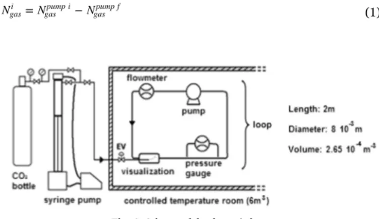
characterize its rheological properties. The loop is mainly composed of stainless steel pipes with an internal diameter of 8 mm (external diameter of 10 mm) and a total length of 2 m. A scheme of the apparatus is shown in Fig. 1. The total volume of the loop is 2.65 10−4m3. The loop is located in a cold room (6 m3) whose temperature
is controlled by PID. Temperature and pressure are maintained within
the range of 268 293 K and up to 3.5 MPa respectively. The dynamic loop is also composed of a glass tube (with an inner volume of around 3 10−5m3) for detecting the formation of hydrate particles and visualiz ing hydrate slurry flow. The loop is equipped with a differential pressure gauge (ABB 265 DS, up to 0.02 MPa, ± 0.04%) to measure the pressure drops caused byfluid flow on a straight line of the loop (0.5 m), and with a pump (AxFlow GC M25, maximum flow rate=0.17 m3h−1) and an electromagneticflowmeter (IFM6080K type
Variflux, ± 0.5%) to control and measure fluid flow. The device is equipped with 6 T type thermocouples ( ± 0.3 K) and 2 pressure gauges (range: 0 5.0 MPa, accuracy 0.05%) (cf.Table 1).
2.2. Gas injection
A syringe pump (1000D ISCO) is used to control the CO2injected
into the dynamic loop to form the CO2hydrate. Initially, gas is directly
injected into the syringe pump which consists of a cylinder with a total volume of around 1000 cm3. Pressure, volume and temperature are
then used to calculate the number of moles of gas inside the syringe pump,Ngaspump i, , based on a real gas equation. Afterwards, when gas is injected into the dynamic loop, the pressure in the syringe pump decreases (at a constant volume) and the number of moles of gas remaining in the syringe pump,Ngaspump f,, can also be determined. The number of moles of gas injected into the loop, Ngas
i
, is the difference between the initial and thefinal number of moles of gas in the syringe pump.
Ngasi =Ngaspump i−Ngaspump f (1)
Table 1
Detailed information on the equipment.
Name Description Range Uncertainty
Pressure gauge ABB 265 DS 0 0.02 MPa ± 0.04% Pump AxFlow GC-M25 0 0.17 m3h1 ( ) Electromagnetic flowmeter IFM6080K-type Variflux 0.01 220 m3h1 ± 0.5% Thermocouples T-type 3 673 K ± 0.3 K Pressure gauges ( ) 0 5.0 MPa ± 0.05%
Nomenclature
N Number of moles of gas, mol
τ Shear stress, Pa τ0 Yield stress, Pa
γ ̇ Shear rate, s−1 n Behavior index, ( ) k Consistency index, (Pa sn)
μ Viscosity, Pa s
Q Volumetricflow rate, l h−1
R Radius, m
L Length, m
u Flow velocity, m s−1 ΔP Pressure drop, Pa
ϕs Hydrate volume fraction, ( )
μ τ γ = ̇ app w w (7) 2.4. Materials used
SDS and CO2 were used for the experiments presented below.
Information on these materials is provided inTable 2. 2.5. SDS properties
SDS is an anionic surfactant that commonly has many practical applications such as detergency, cosmetics, and cleaning. It is an organic compound of formula CH3(CH2)11OSO3Na (shown inFig. 2),
with a molar mass of 288.4 g mol−1and a density of 1.01 g cm-³. More
detailed information about this product can be found in the literature (van Os et al., 1993).
An important physico chemical characteristic of an ionic surfactant is its Krafft point (or Krafft temperature, usually noted TK), where the
solubility of the surfactant is equal to its critical micelle concentration (CMC). The CMC of SDS in water is known to be around 2400 ppm (wt) at ambient conditions (Rosen and Kunjappu, 2012). TK is the
temperature below which the surfactant remains in crystalline form, and above which the solubility of the surfactant increases sharply. SDS has a Krafft point of around 285±4 K (Watanabe et al., 2005) and this value does not drop to a lower temperature in CO2hydrate forming
conditions (Zhang et al., 2007c). It is important to note that under the temperature conditions used here to form the CO2hydrates (i.e. 274
275 K), SDS precipitates and forms a turbid suspension when its concentration is higher than the CMC (Ricaurte et al., 2012).
As regards the use of SDS in hydrate based applications, the additive is usually qualified as a “kinetic hydrate promoter”. At the concentrations used in this study, it was demonstrated that it has no impact on gas hydrate equilibrium (Gayet et al., 2005; Torre et al., 2012). Some authors used SDS to increase storage capacity and induction temperature, and to reduce the induction time for methane (CH4) hydrates (Sun et al., 2003; Ganji et al., 2007).Zhong and Rogers
(2000)claimedfirst of all that the nucleation sites formed by surfactant micelles enhance hydrate formation kinetics. Moreover, they showed that SDS, above its CMC, increases the ethane hydrate formation rate in a quiescent system by a factor greater than 700.Ganji et al. (2007)
reported that only a small amount of SDS (between 300 and 1000 ppm) was necessary to efficiently increase the CH4hydrate formation rate.
Han et al. (2002)studied the impact of SDS on natural gas composed of 90% of CH4, and found that the hydrate gas content was maximized for
an SDS concentration of 300 ppm. Yoslim and Englezos (2008)
indicated that the addition of 2200 ppm of SDS on a methane (90.5%) propane (9.5%) system increased the gas consumption for hydrate formation by a factor of 4.4. The observations made for CO2
hydrates were different however. In this case, several authors (Torre et al., 2011; Lirio et al., 2012) showed that the presence of an additional thermodynamic promoter, such as THF, was needed to observe the effect of SDS on hydrate formation kinetics. In order to have a high rate of CO2 enclathration when SDS is combined with
thermodynamic promoters, Torre et al. (2011) and Ricaurte et al. (2014)stated that the concentration of SDS should be above 1500 ppm. However, the reason why the effect of SDS was different using CO2and
CH4as a hydrate former is not clear to date. It may be due to a different
conformation of SDS molecules interacting in solution with CO2 or
CH4, thus impacting the pre structuration of water molecules to form
hydrate cages (Albertí et al., 2013), or to a competitive adsorption between the surfactant anions (DS−) and bicarbonate (HCO3−) on the
hydrate surface (Zhang et al., 2007c).
As mentioned in the introduction, the mechanism of hydrate formation in the presence of SDS is not thoroughly understood. However, it has been demonstrated both experimentally and numeri cally that SDS micelles are not present under the conditions of hydrate promotion reported in the literature (Di Profio et al., 2005;Zhang et al., 2007a;Albertí et al., 2012). Hydrate nucleation could possibly be promoted by a suitable arrangement of water molecules interacting with the SDS molecules in solution (Lo et al., 2010a). Through observation and experiments carried out on THF and cyclopentane hydrates respectively, it has been found that the DS− anions are adsorbed onto the hydrate surface (Lo et al., 2008; Zhang et al., 2008;Lo et al., 2010b). Several authors (Zhang et al., 2007c;Anklam et al., 2008,Torre et al., 2012) have suggested that SDS could have an anti agglomerant effect on hydrate slurries, which probably results from both the adsorption of DS−on the hydrate surface and electro static repulsions between the adsorbed anions.Kelland (2006)reported that anti agglomerants prevent capillary adhesion by reducing inter facial tension enough to modify the contact angle between hydrate and water.Gayet et al. (2005),Okutani et al. (2008), andTorre et al. (2012)
observed that in the presence of SDS, hydrates grow on the inner sidewalls of the hydrate formation reactor, and suggested that this porous hydrate structure could pump the aqueous phase by capillarity (“capillarity driven mechanism”). Fernandez (2012) indicated that such a mechanism is promoted when SDS concentration is below the CMC. However, although the anti agglomerant effect of SDS has been suggested in many studies, no direct evidence demonstrating this effect on CO2hydrates has been published in the literature to date, even
though it has been observed with other surfactants like Span 80 in the rheology of cyclopentane hydrate (Karanjkar et al., 2016).
3. Experimental results
3.1. Liquid water at atmospheric pressure
Thefirst viscosity measurement tests were carried out on liquid water, a known Newtonian fluid, at 274.5 K under atmospheric pressure. These measurements were performed to verify the accuracy of the method.
Pressure drops were measured at different flow rates. Based on these experimental data, the behavior index n obtained was close to 1 (0.98), while the yield stress τ0 was equal to zero, reflecting the Newtonian behavior of water. These two parameters n and τ0 were determined by the same method as described below for CO2hydrate
slurry. Finally, the apparent viscosity was around 2 mPa.s (close to the theoretical value of 1.8 mPa s for liquid water at 273.15 K). The same tests were performed on another liquid system composed of water and SDS (1500 2000 ppm), without hydrates. The apparent viscosity deduced from these experiments was around 8 mPa s.
3.2. CO2hydrate slurry without additives
The rheological studies carried out on several types of hydrate slurry (CO2, CH4, HC hydrocarbon clathrate hydrates or salt such
as tetrabutylammonium bromide, TBAB semiclathrate hydrates) in different fields of application (oil and gas i.e. agglomeration in pipelines or natural gas transportability and refrigeration and air conditioning) (Pinder, 1964; Austvik and Bjorn, 1992; Andersson and Gudmundsson, 1999; Fukushima et al., 1999; Andersson and Gudmundsson, 2000; Camargo et al., 2000; Fidel Dufour and Herri, 2002; Oyama et al., 2002; Peysson et al., 2003; Darbouret et al., 2005; Fidel Dufour et al., 2006; Xiao et al., 2006; Delahaye et al., 2008; Wang et al., 2008; Ma et al., 2010; Cameirao et al., 2011; Delahaye et al., 2011; Gainville et al., 2011; Hashimoto et al., 2011; Kumano et al. ,2011; Waycuilis et al., 2011; Clain et al., 2012; Peng et al., 2012; Webb et al., 2012; Jerbi et al., 2013; Webb et al., 2013; Zylyftari et al., 2013;
The apparent viscosity, μapp, was thus deduced by dividing the wall shear stress by the wall shear rate (Andersson and Gudmundsson, 2000).
•
Several methods are used, such as rotating, magnetic or plate viscometers, but the most common method applied to hydrate slurries is the capillary viscometer.•
HC hydrates are studied in the organic phase whereas studies on CO2 and CH4 hydrates and salt (such as TBAB) semiclathratehydrates are carried out in the aqueous phase.
•
Hydrate slurry viscosity increases with solid particle fraction, as is the case for most types of slurry (ice, paraffin…).•
Several rheological behaviors can be observed, but hydrate slurries are usually shear thinning/pseudoplastic (viscosity decreases as shear rate increases: Ostwald de Waele or Herschel Bulkley), and sometimes Bingham, which is similar to Herschel Bulkley shear thinning behavior but over a limited shear rate range, as reported on ice slurry (Ayel et al., 2003).As shown inTable 3, some studies were carried out on CO2hydrate
slurries (Delahaye et al., 2008, Jerbi et al., 2013). Experiments were performed in two different experimental systems: in the same loop as the one described in Fig. 1 (Delahaye et al., 2008) or in a loop associated with a stirred tank reactor (Jerbi et al., 2013). In both systems, the authors drew on the same assumptions as those of the present study. In these experiments, it was pointed out that CO2
hydrates have a tendency to agglomerate as the hydrate fraction increases, which results in a lack of control of theflow rate. In addition, the behavior of the CO2hydrate slurryflow was classified into three
categories according to the hydrate fraction (Jerbi et al., 2013), (Delahaye et al., 2008). A summary of these studies is shown in
Table 4. The rheological behavior of CO2 hydrate slurry can be
described using Herschel Bulkley or Ostwald de Waele models. According to Table 4, CO2 hydrate slurry has a pseudoplastic trend
for a hydrate volume fraction above 10%. 3.3. CO2hydrate slurry in the presence of SDS
In order to carry out the experiments with CO2hydrate slurries in
the presence of SDS, it wasfirst of all necessary to determine the right amount of additive to be used in the aqueous phase. As quoted previously from Torre et al. (2011)and Ricaurte et al. (2014), the SDS concentration should be above 1500 ppm. However, an excessive SDS concentration (i.e. 3500 ppm and above) can decrease the promoting effect of this additive (Watanabe et al., 2005; Ricaurte et al., 2014). In addition, an SDS concentration lower than the CMC at ambient conditions (i.e. < 2400 ppm) should be chosen to avoid the crystallization of the surfactant at a temperature below the Krafft point (Dicharry et al., 2016) Consequently, an SDS concentration between 1500 and 2000 ppm was chosen for the present study.
These experiments had two objectives:
First, verify that the presence of SDS decreases CO2 hydrate
agglomeration and thereby improves the flowing conditions of CO2
hydrate slurries.
If thefirst goal is achieved, then the rheological behavior of CO2
hydrate slurries can be investigated in the presence of SDS.
The water SDS aqueous solution was prepared at 293.2 K. In
Fig. 3a, before gas injection, the liquid phase is transparent: the
injection tube and part of the stainless steel loop are clearly visible below the water surface. The solution contains some foam, which is usual in the presence of SDS. InFig. 3b, the gas is injected into the experimental device at 283.2 K. Once P T equilibrium was reached (corresponding to CO2solubility equilibrium, from Diamond and
Akinfiev (2003)), the temperature was decreased to 274 275 K allow ing CO2hydrates to form. As shown inFig. 3a and b, it was possible to
visually distinguish the formation of the CO2hydrate. Indeed, inFig. 3b
(with hydrates) the fluid is more opaque (milky) than in Fig. 3a (without hydrates) and the injection tube is no longer visible.
In all the experiments, CO2hydrate formation was detected in three
different ways:
(i) Observation of hydrate particles in the liquid phase as shown in
Fig. 3b: thefluid becomes milky after hydrate formation. (ii) Pressure decreases and temperature increases as seen inFig. 4:
these changes are due to the exothermic and gas consuming reaction of hydrate formation.
(iii) Significant variation in pressure drops before and after hydrate formation, for example between 13 and 19 mbar as shown in
Fig. 5: this greater pressure drop is due to an increase in viscosity during hydrate slurry formation (appearance of CO2 hydrate
particles in the liquid phase). The greater pressure drop is associated with a local disturbance in theflow rate (slight increase then decrease).
In each experiment, it was noted that the slurryflow significantly improved in the presence of the additive. In fact, there was no visual evidence of any significant agglomeration in the first 48 h after CO2
hydrate formation in the presence of SDS, in contrast to the tests without any additive where agglomeration occurred just a few hours after hydrate formation. After this 48 h period, hydrate agglomeration was observed in some experiments, but in others no agglomeration was observed for several hours after. This behavior confirms the anti agglomerant effect of SDS on hydrate slurries, as assumed in the literature (Zhang et al., 2007c;Anklam et al., 2008; Lo et al., 2008; Zhang et al., 2008; Lo et al., 2010b; Torre et al., 2012), particularly the fact that DS−anions could be adsorbed onto the hydrate surface, which could promote electrostatic repulsions between hydrate particles.
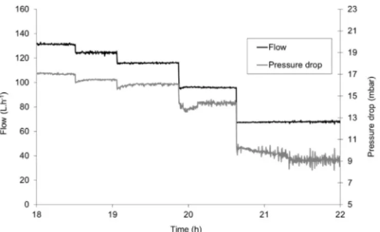
When CO2 hydrates had formed in the loop and liquid vapor
hydrate (L V H) equilibrium had been reached (steady temperature and pressure), different flow rates were applied and the resulting pressures were measured as function of time, as shown inFig. 6. It can be noted that the pressure drops were almost stable, which confirms that the CO2 hydrate slurry did not strongly agglomerate in the
presence of SDS.
In the present experiments, hydrate fractions were set between 0 and 15.5 vol%. The hydrate volume fraction was calculated based on a previous study on hydrate fraction modeling (Marinhas et al., 2007) using P T data at equilibrium and a mass balance of CO2in its different
phases: in vapor phase, dissolved in liquid (corresponding to CO2
solubility equilibrium, from Diamond and Akinfiev (2003)), and in hydrate phase. The behavior index for each hydrate fraction was determined by using the experimental data described in previous work (Jerbi et al., 2010). In short, for each couple (ΔP, u), it was possible to deduce the curveln(D PΔL)vs. ln(Du)
4
8
: the behavior index n corresponds to the slope of this curve, according to Eq.(6). The evolution of the
Table 4
Rheological behavior of CO2hydrate slurries.
Author Flow behavior index Apparent viscosity Slurry behavior
Delahaye et al. (2008) −0.77(1 + lnφs) φ γ 3800φs + 1900 ̇ γw s w φs 3.6 ̇
5.4 −1−0.77(1+ ln ) φ > 10 %s HB type with a pseudoplastic trend
Jerbi et al. (2013) −1.82φs+ 1 0.0018 exp(17.976 ) ̇φ γs w(−1.85φs+1) Pseudoplastic
Webb et al., 2014; Yan et al., 2014) are summarized in Table 3. The table shows several key features of hydrate rheology:
behavior index n as a function of the hydrate fraction is represented in
Fig. 7. It can be noted that the behavior index n is less than 1, suggesting a pseudoplastic behavior. The behavior index n can be expressed by a linear curve as a function of the hydrate fraction, as shown in Eq.(8):
n= −1.077ϕs+ 0.931 (8)
Measurement uncertainty calculations were determined for the behavior index n at ± 8% (Fig. 7), based on the guide to the expression of uncertainty in measurement (GUM) method, from sensor accuracies and the uncertainties related to linear regressions.
The next step consisted in simultaneously determining the other parameters of the general Herschel Bulkley model, Eq. (2), i.e. the consistency index k and the yield stress τ0.Fig. 8shows the evolution of the shear stress τw(deduced from Eq.(4)) as function ofγ ̇w
n
(deduced from Eqs.(5) and (6)) for hydrate fractions between 0 and 15.5 vol%. According to the Herschel Bulkley model, for each hydrate fraction, the slope of each linear curve represents the consistency index k, while the yield stress τ0corresponds to the ordinate at the origin.
InFig. 8, the linear curves pass through the origin. Hence, the yield stress, τ0, for CO2 hydrate slurry in the presence of SDS can be
neglected in afirst approach. At this stage, the rheological model can be represented using the Ostwald de Waele model for hydrate fractions between 0 and 15.5 vol%. It is then possible to represent the evolution of the consistency index k (corresponding to the slope of the curves in
Fig. 8) as a function of the hydrate fraction, as shown inFig. 9.
The empirical equation governing the evolution of the consistency index k can then be expressed as a function of the hydrate fraction in Eq.(9):
k = 0.0125 exp( 18.65ϕs1,315) (9)
where k is expressed in mPa sn.
An exponential was used as a function of the hydrate fraction for
Fig. 3. a: Water and SDS before CO2hydrate formation. b: Water and SDS after CO2hydrate formation.
Fig. 4. Temperature and pressure evolution during CO2hydrate formation in the presence of SDS.
Fig. 5. Flow rate and pressure drop evolution during CO2hydrate formation in the
the consistency index k because it provided the most accurate correla tion for the experimental data. Measurement uncertainty calculations were determined for the consistency index k at ± 9% (Fig. 9).
The rheological model can be expressed by integrating the correla tions of n and k into the Ostwald de Waele model for hydrate fractions between 0 and 15.5 vol%:
τw=kγẇ = 0.0125 exp ( 18.65 ) ̇γ n ϕ w ϕ −1.077 +0.931 s1 315 s (10)
Finally, the experimental values of shear stress and viscosity as a function of the shear rate were compared with those obtained by the
semi empirical equation models(10)and(7), as shown inFigs. 10and
11respectively.
InFig. 10, the model is consistent with the experimental data. For the hydrate fraction of 15.5 vol%, the gap is more significant for the highest shear rates. This can be explained in part by differences between the model and the experimental data, in particular for the
Fig. 6. Variation of the pressure drop andflow as a function of time, for a hydrate formation temperature of 274.5 K.
Fig. 7. Variation of the behavior index n as a function of CO2hydrate volume fraction in
the presence of SDS.
Fig. 8. τwas a function of γ ̇wnfor hydrate fractions between 0 and 15.5 vol%.
Fig. 9. Variation of the consistency index k as a function of the CO2hydrate volume
fraction in the presence of SDS.
Fig. 10. Comparison of experimental and modeled rheograms of CO2hydrate slurries
for hydrate fractions between 0 and15 vol% in the presence of SDS.
Fig. 11. Comparison of experimental and model values for CO2hydrate fractions
consistency index k (Fig. 9).
Concerning the evolution of the apparent viscosity as a function of the shear rate (Fig. 11), CO2hydrate slurry in the presence of SDS has a
pseudoplastic behavior. Moreover, as shown in the literature, the apparent viscosity increases with the hydrate fraction for hydrate slurries. Indeed, for a shear rate of 400 s−1, viscosity is multiplied by approximately a factor of 2 between the liquid phase without hydrate and the slurry at a hydrate fraction of 15 vol%.
3.4. Comparison of the rheological model of CO2hydrate slurry with
the literature
To verify the relevance of the present results, they were compared with data from the literature.Fig. 12compares viscosity data obtained for hydrate slurries in the aqueous phase: CO2hydrate slurries, with or
without a stirred tank reactor, as described in previous work (Delahaye et al., 2008; Jerbi et al., 2013), and CH4hydrate slurries with a stirred
tank reactor calculated from a Bingham model (Andersson and Gudmundsson, 2000).Fig. 12also shows hydrate slurry rheology data fromWebb et al. (2014)obtained in the organic phase with a rotating rheometer, and finally the theoretical correlations ofThomas (1965)
andEinstein (1906).
As shown inFig. 12, hydrate slurry viscosity increases with the hydrate fraction, which is a standard result. Moreover, as pointed out byKauffeld et al. (2005)in a previous study on ice slurry, the relative apparent viscosity (μapp/μwater) calculated according toThomas (1965)
orEinstein (1906)underestimates the viscosity determined on slurries in the aqueous phase. However, the viscosity values differ according to the system. Indeed, for low hydrate fractions ( < 10 vol%), the viscosity of CO2 hydrate slurry with SDS is slightly higher than that of other
types of slurry. This is because the initial viscosity values before CO2
hydrate formation are higher with SDS, respectively 4.9 mPa s with SDS (μapp=8.34 mPa s and μwater=1.67 mPa s at 275 K) and 1 mPa s
(μapp=2 mPa s) for other types of slurry without SDS. However, above a
hydrate fraction of 10 vol% in the case of a simple loop without a stirred tank reactor, the viscosity of the CO2hydrate slurry with SDS
becomes lower than that without SDS. For example, for a hydrate fraction of 15 vol%, the relative apparent viscosity of CO2 hydrate
slurry with SDS is 8.9 mPa.s (μapp=15 mPa s) while it is 14.4 mPa s
(μapp=23 mPa s) without SDS. This reduction in viscosity at a higher
hydrate fraction ( > 10 vol%) could be due to the anti agglomerant property of SDS, which could limit formation of hydrate agglomerates and facilitate hydrate slurryflow. This may also explain why SDS could improve the stability of the CO2hydrate slurry over time, as pointed
out previously in the present paper (no visual evidence of agglomera tion in the first 48 h after CO2hydrate formation in the presence of
SDS, contrary to tests without the additive).
It is also important to note that when a stirred tank reactor is associated with the loop, hydrate slurry viscosity is drastically lowered (close to the theoretical Thomas correlation). This result can be explained by the rheological behavior of hydrate slurries. Indeed, the stirring action in the tank increases the shear rate, which consequently may result in a decrease in the viscosity of the slurry in the loop due to its pseudoplastic behavior (viscosity decreasing with increasing shear rate). This assumption is supported by the results ofAndersson and Gudmundsson (2000)on a CH4hydrate slurry circulating in a loop
equipped with a stirred tank reactor that are close to those obtained in the present work in the same kind of experimental device (loop +reactor), but with CO2hydrate. The results ofWebb et al. (2014)in
the organic phase also show low viscosity values: these data were obtained in a rotating rheometer.
So, the mode of production and use of gas hydrate slurry (with vs. without a stirred tank reactor) seems to have more influence on viscosity than the nature of the guest molecule (CO2vs. CH4) or the
presence of additive in the liquid phase (with vs. without SDS). 4. Conclusion
In the present work, the influence of SDS on the flow and rheological properties of CO2hydrate slurry were studied for thefirst
time in a dynamic loop. The results obtained have shown that CO2
hydrate slurries with an SDS concentration of 1500 2000 ppm (below the CMC level) has a pseudoplastic behavior for hydrate fractions between 0 and 15.5 vol%. Moreover, the presence of SDS facilitates the slurry flow for high solid fractions above 10 vol%: in this case the viscosity of CO2 hydrate slurry with SDS becomes lower than that
without SDS (decrease in viscosity of about 20% for a hydrate fraction of 15.5 vol%). In addition, comparisons with previous studies showed that the presence of a stirred tank reactor associated with the loop allows hydrate slurry viscosity to be drastically lowered (decrease in viscosity of about 73% for a hydrate fraction of 15 vol%). So, in order of importance, the mode of production of a gas hydrate slurry (with vs. without a stirred tank reactor) seems to have more influence on viscosity than the presence of the additive (with vs. without SDS), while the nature of the guest gas molecule (CO2vs. CH4) seems to have
no effect on viscosity.
Another important point is that SDS has an anti agglomerant effect on CO2hydrate slurry. Indeed, the use of SDS improves CO2hydrate
slurry stability over time: there was no visual evidence of any significant agglomeration in the first 48 h after CO2hydrate formation
in the presence of SDS, contrary to previous tests without additives where agglomeration occurred just a few hours after hydrate formation. References
Albertí, M., Pirani, F., Laganaì, A., 2013. Carbon dioxide clathrate hydrates: selective role of intermolecular interactions and action of the SDS catalyst. J. Phys. Chem. A 117, 6991 7000.
Albertí, M., Costantini, A., Laganá, A., Pirani, F., 2012. Are micelles needed to form methane hydrates in sodium dodecyl sulfate solutions? J. Phys. Chem. B 116, 4220 4227.
Aman, Z.M., Olcott, K., Pfeiffer, K., Sloan, E.D., Sum, A.K., Koh, C.A., 2013. Surfactant adsorption and interfacial tension investigations on cyclopentane hydrate. Langmuir 29, 2676 2682.
Andersson, V., Gudmundsson, J.S. 1999. Flow experiments on concentrated hydrate slurries. In: Proceedings of the 1999 SPE Annual Technical Conference and Exhibition:‘Production Operations and Engineering General’. Houston, TX, USA.
Andersson, V., Gudmundsson, J.S., 2000. Flow properties of hydrate-in-water slurries. Ann. N.Y. Acad. Sci. 912, 322 329.
Anklam, M.R., York, J.D., Helmerich, L., Firoozabadi, A., 2008. Effects of antiagglomerants on the interactions between hydrate particles. AIChE J. 54, 565 574.
Austvik, T., Bjorn, M. 1992. The transportability of hydrates in pipes. In: Multiphase transportation III. Roros.
Ayel, V., Lottin, O., Peerhossaini, H., 2003. Rheology,flow behaviour and heat transfer of ice slurries: a review of the state of the art. Int. J. Refrig. 26, 95 107.
Camargo, R., Palermo, T., Sinquin, A., Glenat, P., 2000. Rheological characterization of
Fig. 12. Comparison of the relative apparent viscosity (μwaterat 275 K) of hydrate
Rheological properties of tetra-n-butylphosphonium bromide hydrate slurryflow. Chem. Eng. J. 193 194, 112 122.
Darbouret, M., Cournil, M., Herri, J.M., 2005. Rheological study of TBAB hydrate slurries as secondary two-phase refrigerants. Int. J. Refrig. 28, 663 671.
Delahaye, A., Fournaison, L., Marinhas, S., Martinez, M.C., 2008. Rheological study of CO2hydrate slurry in a dynamic loop applied to secondary refrigeration. Chem. Eng.
Sci. 63, 3551 3559.
Delahaye, A., Fournaison, L., Jerbi, S., Mayoufi, N., 2011. Rheological properties of CO2
hydrate slurryflow in the presence of additives. Ind. Eng. Chem. Res. 50, 8344 8353.
Di Profio, P., Arca, S., Germani, R., Savelli, G., 2005. Surfactant promoting effects on clathrate hydrate formation: are micelles really involved? Chem. Eng. Sci. 60, 4141 4145.
Diamond, L.W., Akinfiev, N.N., 2003. Solubility of CO2in water from 1.5 to 100 °C and
from 0.1 to 100 MPa: evaluation of literature data and thermodynamic modelling. Fluid Ph. Equilib. 208, 265 290.
Dicharry, C., Diaz, J., Torré, J.P., Ricaurte, M., 2016. Influence of the carbon chain length of a sulfate-based surfactant on the formation of CO2, CH4and CO2 CH4gas
hydrates. Chem. Eng. Sci. 152, 736 745.
Dicharry, C., Duchateau, C., Asbaï, H., Broseta, D., Torré, J.P., 2013. Carbon dioxide gas hydrate crystallization in porous silica gel particles partially saturated with a surfactant solution. Chem. Eng. Sci. 98, 88 97.
Einstein, A., 1906. Eine neue Bestimmung der Moleküldimensionen. Ann. Phys. 324, 289 306.
Fernandez, M.J.R., 2012. Séparation Du CO2D′un Mélange CO2-CH4Par Cristallisation
D′hydrates De Gaz: Influence D′additifs Et Effet Des Conditions Opératoires (Ph.D. Thesis). Université de Pau et des pays de l′adour, France.
Fidel-Dufour, A., Herri, J.-M. 2002. Formation and transportation of methane hydrate slurries in aflow loop reactor: influence of a dispersant. In: Proceedings of the International Conference on Multiphase Flow. Alba, Italy.
Fidel-Dufour, A., Gruy, F., Herri, J.-M., 2006. Rheology of methane hydrate slurries during their crystallization in a water in dodecane emulsion underflowing. Chem. Eng. Sci. 61, 505 515.
Fournaison, L., Delahaye, A., Chatti, I., Petitet, J.P., 2004. CO2hydrates in refrigeration
processes. Ind. Eng. Chem. Res. 43, 6521 6526.
Fukushima, S., Takao, S., Ogoshi, H., Ida, H., Matsumoto, S., Akiyama, T., Otsuka, T., 1999. Development of high-density cold latent heat with clathrate hydrate. NKK Tech. Rep. 166, 65 70.
Gainville, M., Sinquin, A., Darbouret, M., 2011. Hydrate Slurry Characterisation for Laminar and Turbulent Lows in Pipelines. ICGH, Edinburgh.
Ganji, H., Manteghian, M., Sadaghiani zadeh, K., Omidkhah, M.R., Rahimi Mofrad, H., 2007. Effect of different surfactants on methane hydrate formation rate, stability and storage capacity. Fuel 86, 434 441.
Gayet, P., Dicharry, C., Marion, G., Graciaa, A., Lachaise, J., Nesterov, A., 2005. Experimental determination of methane hydrate dissociation curve up to 55 MPa by using a small amount of surfactant as hydrate promoter. Chem. Eng. Sci. 60, 5751 5758.
Guilpart, J., Stamatiou, E., Delahaye, A., Fournaison, L., 2006. Comparison of the performance of different ice slurry types depending on the application temperature. Int. J. Refrig. 29, 781 788.
Han, X., Wang, S., Chen, X., Liu, F. 2002. Surfactant accelerates gas hydrate formation. In: Proceedings of the Fourth International Conference on Natural Gas Hydrates. Yokohama, Japan
Hashimoto, S., Kawamura, K., Ito, H., Nobeoka, M., Ohgaki, K., Inoue, Y. 2011. Rheological study on tetra-n-butyl ammonium salt semi-clathrate hydrate slurries. In: Proceedings of the 7th International Conference on Gas Hydrates. Edinburgh, Scotland, United Kingdom.
Jerbi, S., Delahaye, A., Fournaison, L., Haberschill, P., 2010. Design of a New Circulation Loop based on CO2Hydrate Kinetics. Sustainable Refrigeration and Heat Pump
Technology. KTH, Stockholm.
Jerbi, S., Delahaye, A., Fournaison, L., Haberschill, P., 2010. Characterization of CO2
hydrate formation and dissociation kinetics in aflow loop. Int. J. Refrig. 33, 1625 1631.
Jerbi, S., Delahaye, A., Oignet, J., Fournaison, L., Haberschill, P., 2013. Rheological properties of CO2hydrate slurry produced in a stirred tank reactor and a secondary
refrigeration loop. Int. J. Refrig. 36, 1294 1301.
Karanjkar, P.U., Ahuja, A., Zylyftari, G., Lee, J.W., Morris, J, F., 2016. Rheology of cyclopentane hydrate slurry in a model oil-continuous emulsion. Rheol. Acta 55, 235 243.
Kauffeld, M., Kawaji, M., Egolf, P.W., Melinder, A., Davies, T.W., 2005. Handbook on Ice Slurries Fundamentals and Engineering.
Kelland, M.A., 2006. History of the development of low dosage hydrate inhibitors. Energy Fuels 20, 825 847.
Kumano, H., Hirata, T., Kudoh, T., 2011. Experimental study on theflow and heat transfer characteristics of a tetra-n-butyl ammonium bromide hydrate slurry (first report:flow characteristics). Int. J. Refrig. 34, 1963 1971.
Kumar, A., Bhattacharjee, G., Kulkarni, B.D., Kumar, R., 2015. Role of surfactants in promoting gas hydrate formation. Ind. Eng. Chem. Res. 54, 12217 12232.
Lirio, C.Fd.S., Pessoa, F.L.P., Uller, A.M.C., 2012. Storage capacity of carbon dioxide hydrates in the presence of Sodium Dodecyl Sulfate (SDS) and tetrahydrofuran (THF). Chem. Eng. Sci..
Lo, C., Zhang, J., Somasundaran, P., Lee, J.W., 2010. Raman spectroscopic studies of surfactant effect on the water structure around hydrate guest molecules. J. Phys. Chem. Lett. 1, 2676 2679.
Lo, C., Zhang, J.S., Couzis, A., Somasundaran, P., Lee, J.W., 2010. Adsorption of cationic and anionic surfactants on cyclopentane hydrates. J. Phys. Chem. 114,
13385 13389.
Lo, C., Zhang, J.S., Somasundaran, P., Lu, S., Couzis, A., Lee, J.W., 2008. Adsorption of surfactants on two different hydrates. Langmuir 24, 12723 12726.
Ma, Z.W., Zhang, P., Wang, R.Z., Furui, S., Xi, G.N., 2010. Forcedflow and convective melting heat transfer of clathrate hydrate slurry in tubes. Int. J. Heat Mass Transf. 53, 3745 3757.
Marinhas, S., Delahaye, A., Fournaison, L., 2007. Solid fraction modelling for CO2and
CO2-THF hydrate slurries used as secondary refrigerants. Int. J. Refrig. 30, 758 766.
Marinhas, S., Delahaye, A., Fournaison, L., Dalmazzone, D., Furst, W., Petitet, J.P., 2006. Modelling of the available latent heat of a CO2hydrate slurry in an experimental loop
applied to secondary refrigeration. Chem. Eng. Process. 45, 184 192.
Metzner, A.B., Reed, J.C., 1955. Flow of non-newtonianfluids correlation of the laminar, transition, and turbulent-flow regions. AIChE J. 1, 434 440.
Mohammadi, A.H., Richon, D., 2009. Phase equilibria of clathrate hydrates of methyl cyclopentane, methyl cyclohexane, cyclopentane or cyclohexane+carbon dioxide. Chem. Eng. Sci. 64, 5319 5322.
Okutani, K., Kuwabara, Y., Mori, Y.H., 2008. Surfactant effects on hydrate formation in an unstirred gas/liquid system: an experimental study using methane and sodium alkyl sulfates. Chem. Eng. Sci. 63, 183 194.
Oyama, H., Ebinuma, T., Shimada, W., Takeya, S., Nagao, J., Uchida, T., Narita, H. 2002. Viscosity increase before nucleation of CO2gas hydrate. In: Proceedings of the 4th
International Conference on Gas Hydrates. Yokohama, Japon.
Peng, B.-Z., Chen, J., Sun, C.-Y., Dandekar, A., Guo, S.-H., Liu, B., Mu, L., Yang, L.-Y., Li, W.-Z., Chen, G.-J., 2012. Flow characteristics and morphology of hydrate slurry formed from (natural gas+diesel oil/condensate oil+water) system containing anti-agglomerant. Chem. Eng. Sci. 84, 333 344.
Peysson, Y., Maurel, P., Vilagines, R. 2003. Hydrate transportability in multiphaseflow. In: Proceedings of the International Conference on Multiphase: Extending the Boundaries of Flow Assurance.
Pinder, K.L., 1964. Time dependant rheology of the tetrahydrofuran-hydrogen sulphide gas hydrate slurry. Can. J. Chem. Eng. 42, 132 138.
Ribeiro, C.P., Jr, Lage, P.L.C., 2008. Modelling of hydrate formation kinetics: state-of-the-art and future directions. Chem. Eng. Sci. 63, 2007 2034.
Ricaurte, M., Dicharry, C., Renaud, X., Torré, J.P., 2014. Combination of surfactants and organic compounds for boosting CO2separation from natural gas by clathrate
hydrate formation. Fuel 122, 206 217.
Ricaurte, M., Dicharry, C., Broseta, D., Renaud, X., Torré, J.-P., 2012. CO2Removal from
a CO2 CH4Gas Mixture by Clathrate Hydrate Formation Using THF and SDS as
Water-Soluble Hydrate Promoters. Ind. Eng. Chem. Res. 52, 899 910. Rosen, M.J., Kunjappu, J.T., 2012. Surfactants and Interfacial Phenomena. Fourth
edition.
Sloan, E.D., 1998. Clathrate Hydrates of Natural Gases. Marcel Dekker Inc, New York.
Sloan, E.D., Koh, C.A., 2008. Clathrate Hydrates of Natural Gases. Taylor & Francis CRC Press, New York.
Sum, A.K., Wu, D.T., Yasuoka, K., 2011. Energy science of clathrate hydrates: simulation-based advances. MRS Bull. 36, 205 210.
Sun, Z.-g., Wang, R., Ma, R., Guo, K., Fan, S., 2003. Natural gas storage in hydrates with the presence of promoters. Energy Convers. Manag. 44, 2733 2742.
Thomas, D.G., 1965. Transport characteristics of suspension: VIII. A note on the viscosity of Newtonian suspensions of uniform spherical particles. J. Colloid Sci. 20, 267 277.
Torre, J.-P., Ricaurte, M., Dicharry, C., Broseta, D., 2012. CO2enclathration in the
presence of water-soluble hydrate promoters: hydrate phase equilibria and kinetic studies in quiescent conditions. Chem. Eng. Sci. 82, 1 13.
Torre, J.-P., Dicharry, C., Ricaurte, M., Daniel-David, D., Broseta, D., 2011. CO2capture
by hydrate formation in quiescent conditions: in search of efficient kinetic additives. Energy Procedia 4, 621 628.
Trueba, A.T., Rovetto, L.J., Florusse, L.J., Kroon, M.C., Peters, C.J., 2011. Phase equilibrium measurements of structure II clathrate hydrates of hydrogen with various promoters. Fluid Phas. Equilib. 307, 6 10.
van Os, N.M., Haak, J.R., Rupert, L.A.M., 1993. Physico-Chemical Properties of Selected Anionic, Cationic and Nonionic Surfactants. Elsevier Science Publishers, B.V..
Wang, W., Fan, S., Liang, D., Yang, X., 2008. Experimental study onflow characters of CH3CCl2F hydrate slurry. Int. J. Refrig. 31, 371 378.
Watanabe, K., Imai, S., Mori, Y.H., 2005. Surfactant effects on hydrate formation in an unstirred gas/liquid system: an experimental study using HFC-32 and sodium dodecyl sulfate. Chem. Eng. Sci. 60, 4846 4857.
Waycuilis, J., Sirajuddin, H., Rensing, P., 2011. A novel approach to production of hydrate slurries at high process intensity and conceptual applications. ICGH, Edinburgh.
Webb, E.B., Koh, C.A., Liberatore, M.W., 2013. Rheological properties of methane hydrate slurries formed from AOT+Water+Oil microemulsions. Langmuir 29, 10997 11004.
Webb, E.B., Koh, C.A., Liberatore, M.W., 2014. High pressure rheology of hydrate slurries formed from water-in-mineral oil emulsions. Ind. Eng. Chem. Res. 53, 6998 7007.
Webb, E.B., Rensing, P.J., Koh, C.A., Sloan, E.D., Sum, A.K., Liberatore, M.W., 2012. High-pressure rheology of hydrate slurries formed from water-in-oil emulsions. Energy Fuels 26, 3504 3509.
Xiao, R., Wu, S., Tang, L., Huang, C., Feng, Z. 2006. Experimental investigation of pressure-drop of clathrate hydrate slurry (CHS)flow of tetra butyl ammonium
hydrate suspensions in oil dominated systems. Ann. N.Y. Acad. Sci. 912, 906 916.
Cameirao, A., Fezoua, A., Ouabbas, Y., Herri, J.M., Darbouret, M., Sinquin, A., Glénat, P., 2011. Agglomeration of Gaz Hydrate in a Water-in-oil Emulsion: Experimental and Modeling Studies. ICGH, Edimbourg.
Li, N., Song, Z.Y., Niu, S.S., Chen, G.J., 2014. Flow characteristics and rheological properties of natural gas hydrate slurry in the presence of anti-agglomerant in aflow loop apparatus. Chem. Eng. Sci. 106, 99 108.
Yoslim, J., Englezos, P. 2008. The effect of surfactant on the morphology of methane/ propane clathrate hydrate crystals. In: Proceedings of the 6th International Conference on Gas Hydrates (ICGH 2008). Vancouver, British Columbia, Canada.
Yoslim, J., Linga, P., Englezos, P., 2010. Enhanced growth of methane-propane clathrate hydrate crystals with sodium dodecyl sulfate, sodium tetradecyl sulfate, and sodium hexadecyl sulfate surfactants. J. Cryst. Growth 313, 68 80.
Youssef, Z., Delahaye, A., Huang, L., Trinquet, F., Fournaison, L., Pollerberg, C., Doetsch, C., 2013. State of the art on phase change material slurries. Energy Convers. Manag. 65, 120 132.
Zerpa, L.E., Salager, J.L., Koh, C.A., Sloan, E.D., Sum, A.K., 2011. Surface chemistry and gas hydrates inflow assurance. Ind. Eng. Chem. Res. 50, 188 197.
Zhang, J.S., Lee, S., Lee, J.W., 2007. Does SDS micellize under methane hydrate-forming conditions below the normal Krafft point? J. Colloid Interface Sci. 315, 313 318.
Zhang, J.S., Lee, S., Lee, J.W., 2007. Kinetics of methane hydrate formation from SDS solution. Ind. Eng. Chem. Res. 46, 6353 6359.
Zhang, J.S., Lo, C., Somasundaran, P., Lee, J.W., 2007. Competitive adsorption between SDS and carbonate on tetrahydrofuran hydrates. J. Colloid Interface Sci. 341, 286 288.
Zhang, J.S., Lo, C., Somasundaran, P., Lu, S., Couzis, A., Lee, J.W., 2008. Adsorption of Sodium Dodecyl Sulfate at THF hydrate/liquid interface. J. Phys. Chem. C. 112, 12381 12385.
Zhang, P., Ma, Z.W., 2012. An overview of fundamental studies and applications of phase change material slurries to secondary loop refrigeration and air conditioning systems. Renew. Sustain. Energy Rev. 16, 5021 5058.
Zhong, Y., Rogers, R.E., 2000. Surfactant effects on gas hydrate formation. Chem. Eng. Sci. 55, 4175 4187.
Zylyftari, G., Lee, J.W., Morris, J.F., 2013. Salt effects on thermodynamic and rheological properties of hydrate forming emulsions. Chem. Eng. Sci. 95, 148 160. bromide (TBAB) in straight pipe. In: Proceedings of the 10th International
Conference on Thermal Energy Storage. New Jersey, USA.