O
pen
A
rchive
T
OULOUSE
A
rchive
O
uverte (
OATAO
)
OATAO is an open access repository that collects the work of Toulouse researchers and
makes it freely available over the web where possible.
This is an author-deposited version published in :
http://oatao.univ-toulouse.fr/
Eprints ID : 14040
To link to this article : DOI:10.1007/s00348-015-1996-5
URL :
http://dx.doi.org/10.1007/s00348-015-1996-5
To cite this version : Venning, James and Lo Jacono, David and
Burton, David and Thompson, Mark C. and Sheridan, John The effect
of aspect ratio on the wake of the Ahmed body. (2015) Experiments in
Fluids, vol. 56 (n° 6). pp. 1-11. ISSN 0723-4864
Any correspondance concerning this service should be sent to the repository
administrator:
staff-oatao@listes-diff.inp-toulouse.fr
The effect of aspect ratio on the wake of the Ahmed body
J. Venning1 · D. Lo Jacono1,2 · D. Burton3 · M. Thompson1 · J. Sheridan1Due to the wide variability in the shape of ground vehi-cles, Morel (1976) defined a generalised three-dimensional model that produces a wake with features similar to the important ones in automobile wakes. Ahmed et al. (1984) defined a similar body based on the fast-back shape of auto-mobiles that has been accepted as the standard for aerody-namic studies on ground vehicles. The body has a rounded front end and a slanted surface at the trailing edge that pro-duces the major flow structure in the wake: a pair of counter-rotating vortices. These so-called c-pillar vortices (so named due to their formation at the third, or ‘C’, pillar of a vehi-cle) are conical in shape and produce a downwash between them. In this study, we adopt and systematically modify the Ahmed body geometry by changing the aspect ratio in order to understand and characterise the effects of aspect ratio on the wake. Our investigation aims to control the lateral spac-ing of the c-pillar vortices and thereby understand the influ-ence of their spacing on the strength and nature of these vor-tices, the topology of other features within the wake, and, by inference, the drag. As Onorato and Costelli (1984) showed with their control volume momentum analysis, the c-pillar vortices contribute to the drag through energy losses and induced rotational kinetic energy in their cores.
The key parameter varied by Ahmed et al. (1984) was the angle of the slant at the rear of the body. It was found that the drag strongly depended on the slant angle, hav-ing a minimum at 10◦ and a maximum at a critical angle of 30◦, before dropping sharply. Between these critical angles, the wake flow exhibits highly three-dimensional structures (Fig. 1). In addition to the c-pillar vortices, a pair of recir-culation regions (A and B) forms behind the rear surface, and the flow separates from the ground plane due to the expansion of the underbody flow. Beyond the 30◦ critical angle, the flow separates over the backlight (slanted sur-face) (Ahmed et al. 1984; Strachan et al. 2007; Gilliéron
Abstract This paper seeks to further elucidate the wake
of the Ahmed body by investigating how the time-averaged flow structures vary with frontal aspect ratio. High-resolu-tion particle image velocimetry results are provided for eight different width Ahmed geometries at Re√
FA= 3 × 10
4 . It is shown that the narrower the body, the greater the down-wash over the back slant, meaning the flow remains more attached. At a critical aspect ratio ( = 1.9), the flow down-stream changes. The separation over the back slant is shown to be affected by the , and this in turn has a significant effect on the circulation in the c-pillar vortices.
1 Introduction
A large component of the energy used in ground transpor-tation comes from overcoming aerodynamic drag, with typ-ically over 60 % of the total resistive force being aerody-namic drag at highway speeds (Hucho 1993). Much effort has been expended in researching methods to reduce this drag, particularly focusing on the wake region, as approxi-mately 85 % of the drag is produced at a simplified vehi-cle’s rear end (Drouin et al. 2002).
* J. Venning
james.venning@gmail.com
1
Fluids Laboratory for Aeronautical and Industrial Research (FLAIR), Department of Mechanical and Aerospace Engineering, Monash University, Clayton, VIC 3800, Australia
2 Institut de Mécanique des Fluides de Toulouse (IMFT),
CNRS, UPS, Univeristé de Toulouse, Allée Camille Soula, 31400 Toulouse, France
3
Department of Mechanical and Aerospace Engineering, Monash University, Clayton, VIC 3800, Australia
et al. 1999) and the flow is much more two-dimensional. Vino et al. (2005) propose that vortex A and the recircu-lation region over the top of the backlight join into one structure.
It is well known in bluff-body aerodynamics that an increase in aspect ratio of a body tends to reduce three-dimensional effects by increasing the distance between the end-affected flows. Huang et al. (2015) studied the effect of aspect ratio on rectangular plates, finding that at low aspect ratio, the edge vortices stabilise the wake and increase the stall angle. For higher aspect ratios, the flow separation at the leading edge occurs at a lower angle of attack. The effect of aspect ratio on the Ahmed model has not been exhaustively studied to date. Morel (1976) supposed that a change in aspect ratio of a generalised body would merely have a proportional effect, since the effect of c-pillar vor-tices on the overall flow patterns becomes smaller, as only a relatively smaller portion of the base is exposed to them. However, Okada et al. (2005) found that the maximum vor-ticity of an Ahmed model with = 2.2 is much lower than that of a standard = 1.8 body. McQueen et al. (2014) found that the corner vortices generated by the acceleration of the underbody flow increased in strength with increas-ing . Corallo et al. (2015) performed a similar study to the present one with CFD. They found the critical angle of an Ahmed model to be dependent on the aspect ratio. For a slant angle of 25◦, they suggest a critical aspect ratio of 1.5, beyond which the flow separates over the back slant.
In the present paper, we provide details regarding the wake of the Ahmed body as the aspect ratio is varied. The rest of this article is organised as follows. Section 2 describes the experimental methodology and data acqui-sition. Section 3 presents the results of the experiments. A description is given of the wake of the standard width Ahmed body at Re√
FA= 3 × 10
4
, and a comparison is shown with LDA data of Lienhart and Becker (2003). The effects of aspect ratio on the flow structures in the wake are then presented. Section 4 gives some concluding remarks and summarises the key findings.
2 Experimental set-up
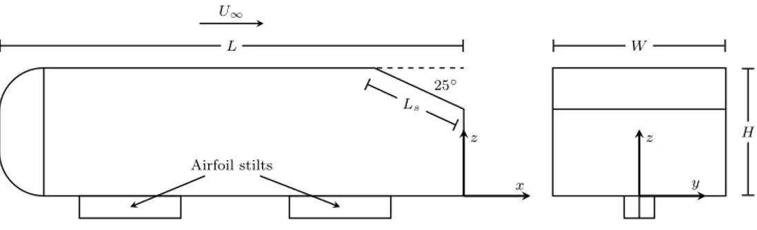
For this study, Ahmed bodies with a slant angle of 25◦ were used. According to Ahmed et al. (1984), this should produce wakes in the high-drag regime far from the criti-cal angle of 30◦. The models were scaled down to 25 % of the original size proposed by Ahmed et al. (1984) to reduce blockage effects (blockage was less than 2 %). The result-ing size for the standard width (AM10) model was 261 mm long × 97 mm wide × 72 mm high, with an aspect ratio ( = W /LS= 1.75). The models were manufactured out of acetal, and the widths were varied between 60 % and 130 % of the standard model, while the height of the models was kept constant. With a freestream velocity of 0.365 ms−1, the Reynolds number based on the square root of the stand-ard body frontal area (FA) was Re√
FA= 3 × 10
4
. The flow velocity was constant for all bodies tested.
A flat plate was used to simulate the ground plane. The plate extended 4.2H upstream of the leading edge of the model and had a 4:1 elliptical leading edge. The models were attached to the ground plane via two symmetric airfoil stilts. The stilts were manufactured out of stainless steel and had a chord of 57 mm and thickness of 17 mm. The ground clearance was 0.17H as defined by Ahmed et al. (1984). This resulted in a boundary layer with height less than one-third that of the clearance between the model and the ground plane at the leading edge of the model. The dis-placement thickness was one-tenth of the ground clearance at the leading edge. The origin of the coordinate system was defined as the base of the model at the rear edge in the symmetry line (Fig. 2).
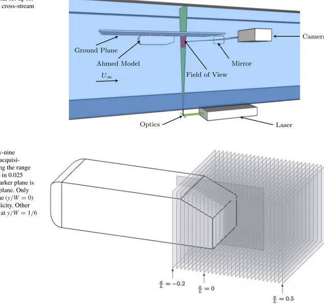
The model (Fig. 2 and Table 1) and ground plane were placed upside down in a water channel at FLAIR (Fluids Laboratory for Aeronautical and Industrial Research) at Monash University, Victoria (Fig. 3). The water channel is a free-surface, closed circuit channel with cross section 600 mm wide × 800 mm high and is 4000 mm long. The model and ground plane were mounted on parallel tracks to allow the position of the laser plane relative to the model to be varied between x/L = −0.2 and x/L = 0.5 (Fig. 4). Fig. 1 Vortex system after Ahmed et al. (1984)
Particle image velocimetry (PIV) was used to quan-tify the flow velocities in the wake of the model. The flow was seeded using Vestosint spherical particles (Vestos-int, Germany) with density 1.016 g/cm3 and mean size 56 µm. These particles were illuminated with two Mini-lite II Continuum lasers (New Wave Research Inc., USA). These were Nd:YAG lasers emitting light at a wavelength of 532 nm and energy 25 mJ. The laser beam was passed through a series of optical components to spread the beam into a 3-mm-thick sheet which illuminated a cross-flow (yz) plane behind the model. This plane was then imaged using a high-resolution pco.4000 CCD camera (pco, Germany). The images were captured through a Nikkor 105 mm lens (Nikkor, Nikon Corporation); the camera was placed per-pendicular to the channel side wall and captured images through a 45◦ mirror mounted in the channel 6H down-stream of the model. We verified that the mirror was not influencing the upstream flow by comparing velocity fields from data taken in an xz plane behind the model both with
and without the mirror in place. There were no measurable differences in the flow.
The PIV vector fields were acquired at 29 different cross-stream (yz) planes downstream of the body (Fig. 4), from x/L = −0.2 to x/L = 0.5 in increment of x/L = 0.025. For
each downstream location, 680 image pairs were gathered,
with a ∆t of 3.5 ms, and a frame rate of 2 Hz. The image pairs were analysed using in-house cross-correlation soft-ware (Fouras et al. 2007) with a window size of 32 × 32 pixels and an overlap of 75 %. With a region of interest of 2368 × 1600 pixels and a magnification factor of 13.84 px/ mm, the field of view was 1.75W × 1.6H, and the result-ant vector field was 293 × 197 vectors, with vectors spaced every 0.58 mm (0.006W).
Streamwise (xz) velocity fields were also acquired at
three spanwise positions: y/W = 0 (symmetry plane),
y/W = 1/6, and y/W = 1/3. For each plane, 242 image pairs were acquired at a resolution of 4008 × 2672. The magnification factor was 26.07 px/mm, resulting in a field of view of 0.6L × 1.4H. The cross-correlation parameters were the same as for the yz planes, resulting in a vector
field of 498 × 331 vectors which were spaced every 0.3 mm (0.003H). Convergence of the mean flow (via variance of the fluctuating cross-velocity product from the cumula-tive mean) was shown to occur (within 2 %) after 100 pairs, and therefore, 242 pairs were deemed sufficient.
The flow quality in the channel and freestream veloc-ity was quantified using PIV. For a freestream velocveloc-ity of 0.365 ms−1, the in-flow conditions were a turbulence inten-sity (Iu) of less than 0.5 % and non-uniformity of ±1 %
across the usable test section.
The Ŵ2 field as described by Graftieaux (2001) was used to define the bound of a vortex. Ŵ2 is a Galilean-invariant scalar related to the rotation of the fluid in a region of inter-est around each point. It is not influenced by the magnitude of velocity vectors, but rather the direction of each vector.
For a point P, Ŵ2 is defined by:
where N is the number of points in the Ŵ
2 interrogation region R and θ is the angle between the fluctuating velocity vector and a line between the origin of that vector and the point P. The size of the square region, R, used in this study is 41 × 41 vectors. (1) Ŵ2(P) = 1 N R sin (θ )
Table 1 Model geometries
Bold faced row indicates the scaled geometry matching that of the standard Ahmed body
Name Width % standard Width (mm) Height (mm)
AM06 60 58.4 72.3 1.05 AM07 70 68.1 72.3 1.23 AM08 80 77.8 72.3 1.40 AM09 90 87.5 72.3 1.58 AM10 100 97.3 72.3 1.75 AM11 110 107.0 72.3 1.93 AM12 120 116.7 72.3 2.10 AM13 130 126.4 72.3 2.28 W H L U∞ Ls 25◦ z x z y Airfoil stilts
3 Results
3.1 Comparison with previous work
The present results were compared with Lienhart and Becker (2003) who provide wind tunnel laser Doppler ane-mometry (LDA) data behind a standard Ahmed model at a Reynolds number of Re√
FA= 8.9 × 10
5
, an order of mag-nitude higher than this study. While Lienhart and Becker used four cylindrical stilts mounted at the outer edges of the Ahmed body, the current experiment used two airfoil stilts in the symmetry plane. When the stilts are on the outside of the body, the underbody flow is likely to be accelerated between them, while for this study, the symmetry plane is in the wake of the struts, causing a slower flow. This is demonstrated in Fig. 5a where there is a large discrepancy near z/H = 0. The other notable difference between this
study and the previous LDA data of Lienhart and Becker is that the wake deficit is larger in this study. Figure 5b
shows this difference in the streamwise velocity plane. This is consistent with the findings of Spohn and Gilliéron (2002) who showed that the size of separated regions tends to decrease with Reynolds number. However, despite these differences, the major streamwise structures are consistent with Lienhart and Becker (2003), as can be seen in Fig. 6.
While the present study was performed at a relatively low Reynolds number, the major flow structures are com-parable to those at higher Re. Thus, it is likely that our results are applicable to higher Re range, even though there might be some Reynolds number dependence of the critical aspect ratio (discussed later), which depends on whether the separating flow from the slant reattaches again.
3.2 Flow structures for the standard width Ahmed model
The PIV data allowed the time-mean structures in the wake to be visualised and quantified. Figure 7 shows four
Fig. 3 Experimental set-up for PIV acquisition in cross-stream
(yz) planes Field of View Ahmed Model Ground Plane Laser Optics Mirror Camera U∞
Fig. 4 The twenty-nine cross-stream PIV acquisi-tion planes covering the range
−0.2 ≤ x/L ≤ 0.5 in 0.025 increments. The darker plane is
a streamwise (xz) plane. Only
the symmetry plane (y/W = 0)
is shown for simplicity. Other
planes are located at y/W = 1/6
downstream planes behind the standard width Ahmed model. The Ŵ2 criterion was used to quantify the rotation of the flow. In Fig. 7a at x/L = 0.1, three structures are
pre-sent. The c-pillar vortex is shown in red (positive rotation) near the end of the slant and at the side edge of the body. The other positively rotating structure at this downstream location is the corner vortex. This forms from accelerated flow under the body rolling up over the bottom corner. These vortices are (presumably) suppressed in most Ahmed model experiments due to the stilts being on the outside. They have been seen in other studies with clean underbod-ies or stilts in the centreplane (e.g. Strachan et al. 2007; Krajnovic and Davidson 2004; McQueen et al. 2014). The third structure evident in this plane is the blue (nega-tive rotation) structure below the c-pillar vortex. This is the streamwise element of structure B (Fig. 1), which forms as the flow separates at the bottom edge of the body. It is
a predominantly spanwise structure (Fig. 8) and does not extend far downstream (Fig. 7b).
Slightly further downstream at x/L = 0.2, Fig. 7b
shows the persistence of the c-pillar and corner vortices, but recirculation structure B is no longer visible. By this downstream position, a new structure has emerged (struc-ture D), which is formed as the underbody flow expands significantly downstream of the end of the body. This causes the boundary layer on the ground plane to separate at x/L = 0.1, with a local separation zone resulting (see
Fig. 8a). This structure does not extend far in the spanwise direction (notice in Fig. 8c that the bubble is no longer vis-ible), and the associated boundary layer vorticity is tilted into the streamwise direction. Interestingly, this vortical structure is not depicted in Ahmed’s schematic of the mean flow topology, reproduced in Fig. 1, although it does appear in the study of Drouin et al. (2002) at a Reynolds number an order of magnitude higher than this study. Hence, this suggests that it is not generated because of the lower Reyn-olds number, although of course, it might be amplified by it. Figure 7a, b shows the sudden development of this struc-ture. Further downstream, the associated boundary layer vortex filaments tilt away from the symmetry plane towards the corner vortex.
Velocity/U∞ -0.5 0 0.5 1 z/H 0 0.2 0.4 0.6 0.8 1 1.2 (a) x L = 0.084 Velocity/U∞ -0.5 0 0.5 1 z/H 0 0.2 0.4 0.6 0.8 1 1.2 (b) x L=0.420
Fig. 5 Comparison of time averages of streamwise (squares) and vertical velocity (circles) profiles across the symmetry plane at two downstream positions in the wake of the standard width Ahmed model. The black symbols represent the PIV data from the present
study (Re√
FA= 3 × 10
4
), and only one in five points is shown for clarity. The grey symbols are LDA data from Lienhart and Becker
(2003) (Re√
FA= 8.9 × 10
5 )
Fig. 6 Comparison of time-averaged cross-stream (yz) velocity data represented by vectors. Left is LDA data from Lienhart and Becker
(2003), right is PIV data from the present study. One in sixty-four
PIV vectors shown for clarity. Freestream velocity is towards the observer. Half of symmetry plane shown for brevity
At x/L = 0.3 (Fig. 7c), the horseshoe vortex starts to
merge with the corner vortex, and by x/L = 0.4 (Fig. 7d),
the vortices have merged. The c-pillar vortex is also mov-ing downwards, driven by the downwash from the opposite c-pillar vortex. These vortices merge with the corner and horseshoe vortices.
The spanwise structures are shown in Fig. 8. The sub-figures, which represent different spanwise planes, show streamlines based on the time-mean flow, with coloured contours of spanwise vorticity overlaid. Note that the streamlines are used to indicate the approximate local flow direction and should not be interpreted to show the trajecto-ries of fluid particles based on the mean flow. In particular, in the centerplane, since symmetry enforces a zero span-wise velocity component, the foci shown in that plane can-not be real.
The streamlines clearly indicate the recirculation regions A and B, which are generated by the flow separation at the back of the body. The separation region D, off the boundary
layer, is seen in the symmetry plane (Fig. 8a), and a very small separation is seen at y/W = 1/6 (Fig. 8b). Note that the ‘banding’ of positive, negative, and positive vorticity in the y/W = 1/3 plane is due to the plane slicing through the
Fig. 7 Downstream evolution of vortical structures in the wake of
AM10 ( = 1.75). One in one hundred time-averaged velocity
vec-tors is shown for clarity. The vertical black dashed line represents
the symmetry plane. Filled contours are Ŵ2, with red representing
positive (counter-clockwise) rotation and blue representing negative
(clockwise) rotation, with levels between ±1. Freestream velocity is
towards the observer
Fig. 8 Spanwise vorticity and velocity streamlines in three xz planes in the time-averaged wake of the standard width model (AM10). Pos-itive vorticity (clockwise, red) and negative vorticity
c-pillar vortex. The main structures in the flow contributing to the downstream wake can be seen in Figs. 9 and 10.
3.3 Circulation and the effects of aspect ratio
The circulation in the c-pillar vortex was determined by integrating the out-of-plane vorticity across the cross section of the vortex. The bound was defined as where Ŵ2= ±2
π (Graftieaux 2001). The vorticity was non-dimen-sionalised with the freestream velocity and the square root of the frontal area.
The circulation as it varies with downstream position and aspect ratio is given in Fig. 11; in the standard width geometry (AM10), several trends can be seen. Firstly,
there is an increase in the circulation over the slant until
x/L = 0.1, as the boundary layer on the side surface of the
body rolls over the slant edge. This explains the growth of circulation up until x/L = 0, where the body ends.
Accord-ing to Kelvin’s theorem, circulation is a conserved quantity in a vortex tube; in an incompressible flow, vorticity origi-nates at the solid surfaces of the body. Since the stream-wise vorticity in the c-pillar vortex is increasing even after the body ends at x/L = 0, this vorticity must come from
another plane. A plausible hypothesis is that the vorticity is fed in from the recirculation region A. While this struc-ture is initially spanwise (Fig. 7), vortical fluid feeding along the core is tilted into the streamwise direction giving it the same sign as the corresponding c-pillar vortex; this structure is consistent with the vortex system described by Hucho (1993). While Hucho describes vortex A as having low circulation, he presents no data to support this. How-ever, our data show that the circulation in A has 45 % as much circulation as the slant recirculation region, and B has 30 %, using the Ŵ2 criterion for calculating the bounds of these regions. These data and the increase in the circula-tion of the c-pillar vortex show that this structure contains significant circulation. While A and B may be sections of the standard time-averaged toric structure, the increased circulation of A compared to B suggests that not all the cir-culation is bound in this toroid, and some may be being fed into the c-pillar vortex.
From x/L = 0.1 to x/L = 0.3, the circulation remains
constant. At x/L = 0.3, however, there is a sudden rise in
the circulation. This increase occurs due to the merging of three vortex systems: the c-pillar vortex, the corner vortex,
Fig. 9 The flow topology of the standard width (AM10) Ahmed model. Skin friction lines on the back surface are calculated from PIV data near the surface. The three-dimensional structure is an isosurface
of Ŵ2 at 2/π
Corner
C
A
B
Horseshoe
Slant RecirculationFig. 10 Vortex structure schematic in the wake of the standard width Ahmed body, with lines indicating location of vortex cores. The
structure is dashed for y/W < 0 and solid for y/W > 0. Spanwise
rotation indicated by black arrows, streamwise rotation indicated by
red or blue arrows for positive or negative rotation, respectively
Downstream Position(x/L) -0.2 0 0.2 0.4 Circulation 0 2 4 6 8
AM06 AM07 AM08 AM09
AM10 AM11 AM12 AM13
Fig. 11 Time-averaged circulation (non-dimensionalised) in the c-pillar vortex as it varies with downstream location and aspect ratio. Darker lines represent wider bodies. The vertical dotted lines denote
and the horseshoe vortex. For the AM10 model, this merger takes place at x/L = 0.3, causing a significant increase in
circulation. From x/L = 0.375 onwards, the circulation
remains approximately constant. The streamwise circula-tion in each of the component vortices is given in Table 2.
For all the geometries tested, there is an increase in the circulation in the c-pillar vortex from the start of the slant to x/L ≈ 0.1. From this point onwards, there are two
separate regimes. The circulation of the narrower five bod-ies increases between x/L = 0.1 and x/L = 0.4. This
sec-ondary increase in circulation is due to the merging of the c-pillar vortex with the corner vortex. This increase occurs at different points for the different width bodies, but by
x/L = 0.4, the circulation has again reached a constant
level, and the increase is proportionally constant, as shown in Fig. 12.
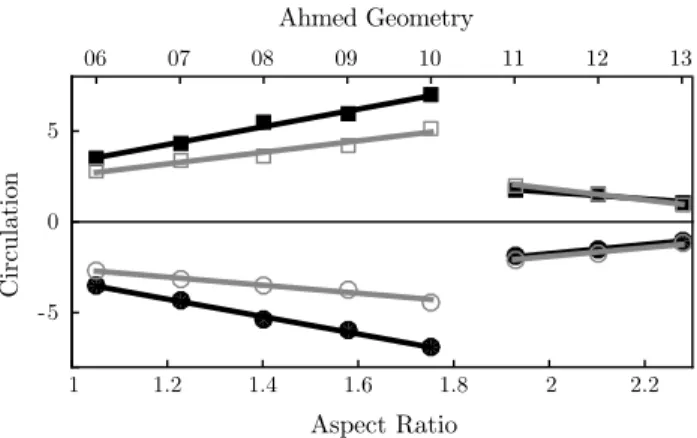
The wider three models have significantly less circula-tion across the measurement domain. The reason for this is twofold: firstly, the additional circulation from vortex A is considerably reduced, and secondly, the corner vortex does not merge with the c-pillar vortex as far downstream as we measured, though it is proposed that eventually these two vortices will merge. Furthermore, while the narrower five bodies show an increase in circulation with width, this trend is reversed for the widest three (Fig. 12).
The large difference in circulation in the c-pillar vortices between the bodies with < 1.8 and those with > 1.9 stems from the separation over the back slant (Fig. 13). For the narrowest five cases, the stronger induced downwash between the two c-pillar vortices promotes the reattach-ment of the flow over the slant. In the regimes where the flow reattaches over the slant, the vorticity built up in this recirculation zone must be fed downstream by some mech-anism; since the flow is attached, the initially spanwise vor-ticity becomes entrained through the spanwise circulation bubble and is tilted into the c-pillar vortices.
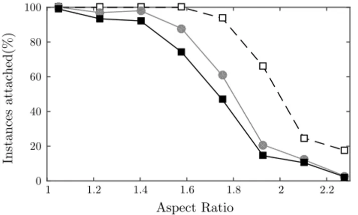
When the flow is separated, this vorticity can be shed downstream directly as spanwise vorticity. Figure 14 shows the percentage of time the flow remains attached for each aspect ratio. This is calculated by comparing the pitch angle of the velocity vector at each snapshot at the
end of the slant. If the pitch angle is aligned with the slant, then the flow is defined as attached. It is clear that the nar-rower bodies have much more attached flow over the rear slant. For all cases, the flow was more separated closer to the symmetry plane, further from the c-pillar vortices. Fig-ure 15 supports this by finding the reattachment length as a function of aspect ratio and spanwise position. The wider the body, the further down the slant the flow reattaches, if it reattaches at all.
This behaviour is similar to that seen for a standard width Ahmed geometry as it passes the critical slant angle. At angles lower than the critical, the partially attached flow serves to strengthen the c-pillar vortices, causing a lower core pressure and hence higher drag. Conversely, past the critical angle, the flow separates from the backlight and has significantly lower drag.
While the flow in the high-drag regime for the standard body (α < 30°) is recognised as three-dimensional, for > 1.9, the flow is in a sense much more two-dimensional.
Figure 16 shows the vertical velocity as it varies with span-wise position. It is clear that spanspan-wise position has little effect on the flow velocity for > 1.9, while in the nar-rower cases, the variation across the span is significant.
The turbulence levels in the wake also increase with (Fig. 17), indicating a significant change in the wake topol-ogy. There is a clear correlation between Figs. 17 and 14 showing that the separation that occurs for the wider bodies causes the increase in turbulence intensity in the wake. This is consistent with our hypothesis that there is increased spanwise vorticity shedding into the wake due to the separation.
Figure 18 shows the wake structure of three geometries: AM08, which has attached flow and no groundplane horse-shoe vortex; AM10, which has attached flow over the slant
Table 2 The circulation in each of the component vortices of Fig. 7
Italics represent vortex merging
Plane CPV Corner D B x/L = 0 3.567 0.520 x/L = 0.1 4.673 0.363 −0.744 x/L = 0.2 4.917 0.213 0.382 x/L = 0.3 4.818 0.999 x/L = 0.4 6.870 Aspect Ratio 1 1.2 1.4 1.6 1.8 2 2.2 Circulatio n -5 0 5 Ahmed Geometry 06 07 08 09 10 11 12 13
Fig. 12 Variation of the time-averaged circulation
(non-dimensional-ised) in the c-pillar vortex at two downstream locations, x/L = 0.1 in
grey and x/L = 0.4 in black. Positive circulation (squares) and
and the groundplane horseshoe vortex; and AM12, which has separated flow and the groundplane vortex. The skin friction lines on the back surface of AM08 and AM10 show a negative bifurcation line near the back slant. This is because when the slant boundary layer separates at the end of the body, there exists both the separation zone A (in red) and a much smaller secondary structure above (not shown). In the wider case (AM12), this negative bifurcation line
disappears since there is no secondary structure because the flow has already separated across the slant.
4 Conclusions
High-resolution PIV data taken in the wakes of different width Ahmed bodies show the effect of aspect ratio on their
Fig. 13 Time-averaged spanwise vorticity and
veloc-ity streamlines in xz planes at
y/W = 0. Positive vorticity (red) and negative vorticity (blue). Vorticity is non-dimen-sionalised, and levels are
time-averaged wake structures. The models were investi-gated in the FLAIR water channel at Monash University.
The downstream evolution of the c-pillar vortices was quantified for each case and found to be consistent with them comprising of four elements. (1) The side shear lay-ers roll up over the slant side edges, feeding the c-pillar vortices that advect downstream, forming the main trailing vortex structures. (2) The spanwise recirculation region (A in Fig. 1) feeds spanwise vortical fluid along the core out-wards from the centreplane, combining it with the c-pillar flow and in doing so tilting the vorticity into the stream-wise direction. In addition, as these trailing vortices move downstream, they merge with (3) the corner vortices gener-ated from the underbody and (4) with a horseshoe vortex caused by the expansion of the underbody flow away from the groundplane. This horseshoe vortex was strengthened with increasing .
The wake was shown to exist in one of two regimes. In the first regime ( < 1.9), the flow over the top rear edge predominantly reattaches before reaching the rear edge of the slant. In this case, the spanwise vorticity fed into the recirculation region advects into (and combines with) the trailing vortex structures, as described above. In the second regime ( > 1.9), the flow separates over the slant, but on average fails to reattach, and thus, this spanwise vorticity is shed downstream directly. This causes the circulation in the trailing vortices to be much lower than in the first regime.
The increase in aspect ratio past the critical has a similar effect to increasing the slant angle past the critical 30◦ for the standard width model. When varying the slant angle, previous research (Ahmed et al. 1984) has seen a significant drop in the drag coefficient once the flow is separated. It is a plausible hypothesis that the same effect
Aspect Ratio 1 1.2 1.4 1.6 1.8 2 2.2 Insta n ce s at ta ch ed (% ) 0 20 40 60 80 100
Fig. 14 Ratio of instantaneous frames with the flow attached at the end of the slant to those with the flow separated. Symmetry plane y/W = 0 (filled square), y/W = 1/6 (filled circle), and y/W = 1/3
(open square) Aspect Ratio 1 1.2 1.4 1.6 1.8 2 2.2 Reattachment Len gth 0 0.2 0.4 0.6 0.8 1
Fig. 15 Reattachment length of time-averaged flow along the slant.
Symmetry plane y/W = 0 (filled square), y/W = 1/6 (filled circle),
and y/W = 1/3 (open square)
Aspect Ratio 1 1.2 1.4 1.6 1.8 2 2.2 w/ U∞ (% ) -5 -4.5 -4 -3.5 -3 -2.5 -2
Fig. 16 Time average of vertical velocity at a point x/L = 0, z/H = 1. Symmetry plane y/W = 0 (filled square), y/W = 1/6 (filled circle), and y/W = 1/3 (open square)
Aspect Ratio 1 1.2 1.4 1.6 1.8 2 2.2 Iw (% ) 0 20 40 60 80 100
Fig. 17 Vertical turbulence intensity at a point x/L = 0, z/H = 1.
Symmetry plane y/W = 0 (filled square), y/W = 1/6 (filled circle),
would be seen when varying the aspect ratio, with higher geometries experiencing lower drag coefficients.
Acknowledgments The authors would like to thank Mr T. McQueen and Ms R. Gardiner for their assistance with the data acqui-sition for this experiment. The authors would like to acknowledge the financial support of the Australian Research Council (ARC) through Linkage Project LP0991170 and the Centre National de la Recherche Scientifique (CNRS) through Grant No. PICS161793 under the Projet International de Coopération Scientifique.
References
Ahmed S, Ramm G, Faitin G (1984) Some salient features of the time-averaged ground vehicle wake. Tech rep, Society of Auto-motive Engineers Inc, Warrendale, PA
Corallo M, Sheridan J, Thompson MC (2015) Effect of aspect ratio on the near-wake flow structure of an Ahmed body. J Wind Eng Ind Aerodyn (submitted)
Drouin V, Giovannini A, Gillieron P (2002) Topology and characteri-zation of the vortical near-wake flow over a simplified car model. In: Proceedings of the Bluff body wakes and vortex induced vibrations (BBVIV3) conference, Port-Douglas, Australia Fouras A, Lo Jacono D, Hourigan K (2007) Target-free stereo
PIV: a novel technique with inherent error estimation and
improved accuracy. Exp Fluids 44(2):317–329. doi:10.1007/
s00348-007-0404-1
Gilliéron P, Renault SA, Golf A, Cedex G (1999) Modelling of sta-tionary three-dimensional separated air flows around an Ahmed reference model. In: Third international workshop on vortex
flows and related numerical methods, pp 173–182. doi:10.1051/
proc:1999016
Graftieaux L (2001) Combining PIV, POD and vortex identification algorithms for the study of unsteady turbulent swirling flows. Meas Sci Technol 12:1422
Huang Y, Venning J, Thompson MC, Sheridan J (2015) Vortex separa-tion and interacsepara-tion in the wake of inclined trapezoidal plates. J
Fluid Mech 771:341–369. doi:10.1017/jfm.2015.160
Hucho W (1993) Aerodynamics of road vehicles. Annu Rev Fluid Mech 25:485–537
Krajnovic S, Davidson L (2004) Large-eddy simulation of the flow around simplified car model. Soc Automot Eng.
doi:10.4271/2004-01-0227
Lienhart H, Becker S (2003) Flow and turbulence structure in the wake of a simplified car model. SAE Tech Pap.
doi:10.4271/2003-01-0656
McQueen T, Venning J, Sheridan J (2014) Effects of aspect ratio on the wake dynamics of the Ahmed body. In: Proceedings of the 19th Australasian Fluid Mechanics Conference, Melbourne, Vic-toria, December
Morel T (1976) The effect of base slant on the flow pattern and drag of three-dimensional bodies with blunt ends. In: Symposium on aerodynamic drag mechanisms of bluff bodies and road vehicles, pp 216–217
Okada M, Sheridan J, Thompson M (2005) Effect of width-to-height ratio on wake structures of simplified vehicle geometry. In: Pro-ceedings of the Fourth conference on bluff body wakes and vor-tex-induced vibrations-BBVIV4, pp 243–246
Onorato M, Costelli A (1984) Drag measurement through wake
anal-ysis. SAE Tech Pap. doi:10.4271/840302
Spohn A, Gilliéron P (2002) Flow separations generated by a simpli-fied geometry of an automotive vehicle. In: IUTAM symposium: unsteady separated flows
Strachan RK, Knowles K, Lawson NJ (2007) The vortex structure behind an Ahmed reference model in the presence of a
mov-ing ground plane. Exp Fluids 42(5):659–669. doi:10.1007/
s00348-007-0270-x
Vino G, Watkins S, Mousley P, Watmuff J, Prasad S (2005) Flow structures in the near-wake of the Ahmed model. J Fluids Struct
20(5):673–695. doi:10.1016/j.jfluidstructs.2005.03.006
Fig. 18 The time-averaged flow topology as it varies with aspect ratio. Skin friction lines on the back surface are calculated from PIV data near the surface