HAL Id: hal-03073955
https://hal.archives-ouvertes.fr/hal-03073955
Submitted on 16 Dec 2020HAL is a multi-disciplinary open access archive for the deposit and dissemination of sci-entific research documents, whether they are pub-lished or not. The documents may come from teaching and research institutions in France or abroad, or from public or private research centers.
L’archive ouverte pluridisciplinaire HAL, est destinée au dépôt et à la diffusion de documents scientifiques de niveau recherche, publiés ou non, émanant des établissements d’enseignement et de recherche français ou étrangers, des laboratoires publics ou privés.
Concurrent and coupled resolution of fluid flow and solid
deformation in solidification processes
S Zhang, G Guillemot, C-A Gandin, Michel Bellet
To cite this version:
S Zhang, G Guillemot, C-A Gandin, Michel Bellet. Concurrent and coupled resolution of fluid flow and solid deformation in solidification processes. MCWASP XV, 15th Int. Conf. on Modeling of Casting, Welding and Advanced Solidification Processes, J. Olofsson, J.H. Hattel, A.K. Dahle, Jun 2020, Online conference, Jönköping, Sweden. �10.1088/1757-899x/861/1/012068�. �hal-03073955�
IOP Conference Series: Materials Science and Engineering
PAPER • OPEN ACCESS
Concurrent and coupled resolution of fluid flow and solid deformation in
solidification processes
To cite this article: S Zhang et al 2020 IOP Conf. Ser.: Mater. Sci. Eng. 861 012068
View the article online for updates and enhancements.
Content from this work may be used under the terms of theCreative Commons Attribution 3.0 licence. Any further distribution of this work must maintain attribution to the author(s) and the title of the work, journal citation and DOI.
Published under licence by IOP Publishing Ltd
MCWASP XV 2020
IOP Conf. Series: Materials Science and Engineering 861 (2020) 012068
IOP Publishing doi:10.1088/1757-899X/861/1/012068
1
Concurrent and coupled resolution of fluid flow and solid
deformation in solidification processes
S Zhang, G Guillemot, C-A Gandin and M Bellet
MINES Paristech, PSL Research University, CEMEF – Centre de Mise en Forme des Matériaux, CNRS UMR 7635, CS 10207, 1 Rue Claude Daunesse, 06904 Sophia Antipolis cedex, France
E-mail : [email protected]
Abstract. Control of macrosegregation phenomena and deformation related defects is the main issue in solidification processes. Numerical modelling of casting provides an answer to industrial needs to master these defects. As a first step, it is essential to achieve a concurrent computation of the fluid flow in the bulk liquid and stress-strain evolution in the already solidified regions. For this specific purpose, a partitioned solution algorithm is developed to model both ingot casting and continuous casting processes: liquid flow induced by natural convection or filling step, solidification shrinkage as well as thermal deformation of solid phase are all taken into consideration. This article is mainly composed of two parts. In the first part, details of the model itself are described. In the second part, applications dedicated to steel solidification are proposed.
1. Introduction
One of the most critical modeling difficulties encountered in solidification processes is the concurrent computation of fluid flow and solid deformation. More precisely, the difficulty lies in the stiffness differences between solid and liquid regions and the explicitly un-describable solid/liquid interface at its microscopic scale. In the current state-of-the-art, there are two types of solutions for this numerical issue: monolithic and partitioned algorithms. In monolithic solution, interactions between the solid and liquid phases are considered as a strong interaction problem. Macroscopic governing equations are developed by using the volume averaging method, thus scaling up physical problems from its dendritic scale to that of the cast product. These equations are then coupled and solved in a single resolution system [1, 2]. The main drawback of this approach is that it requires huge computational resources preventing its application to large industrial casting processes. Typically, a monolithic algorithm consists in the resolution of at least seven unknowns, i.e. velocity vectors in the liquid and solid regions plus pressure, or eventually of nine unknowns if taking into consideration the temperature and solute concentration fields. It is then preferable to consider the interactions between solid and liquid phases as a weak interaction problem, in which the fluid flow computation and the stress-strain analysis are treated as two subproblems. Governing equations respective to each subproblem are solved in two different steps and then coupled [3, 4]. Recently, Zhang et al. [4] proposed an original partitioned solution algorithm for the current modeling of fluid flow and solid deformation for solidification processes. However, this algorithm was developed under the specific hypothesis that the movement of the solid phase is negligible compared to that of the fluid flow, which is indeed true for most ingot casting (IC)
MCWASP XV 2020
IOP Conf. Series: Materials Science and Engineering 861 (2020) 012068
IOP Publishing doi:10.1088/1757-899X/861/1/012068
2
processes but not for continuous casting (CC). The movement of the solid shell (about several centimeters per second) in industrial CC can be no more neglected compared to that of the fluid flow.
A concurrent and coupled solution algorithm is proposed presently in continuity with this first contribution [4]. The present algorithm extends this work to cover both IC and CC processes. The global non-steady-state resolution strategy is chosen to model CC processes, ensuring continuous increase of the metal volume during the casting process [5]. The Arbitrary Lagrangian-Eulerian (ALE) method is used to update the mesh grid, considering the metal in the fully solid state as Lagrangian [6]. At each time increment, the momentum and mass conservation equations are solved twice at macroscopic scale, respectively in a first solid-oriented resolution step (STEP I) and in a second liquid-oriented resolution step (STEP II). From STEP I, the velocity and pressure fields in the already solidified regions and the associated stress-strain fields are deduced. Subsequently in STEP II, the liquid flow and pressure fields in the bulk liquid and mushy regions are calculated through the resolution of the Navier-Stokes equations based on the volume averaging method. Interactions between the solid and liquid phases in the mushy zone are taken into consideration at this second step through the Darcy-type momentum exchange terms, modeling the resistance of the solid skeleton to the fluid flow. All conservation equations are formulated in a level set framework in order to track the metal/gas interface during the solidification processes. Besides, the current resolution algorithm is coupled with an existing non-linear energy solver to calculate the temperature field [7]. The present paper includes a synthetic presentation of the resolution scheme, followed by an application to a three dimensional (3D) industrial CC process.
2. Numerical model 2.1. Level set method
A gas subdomain is introduced above the metal subdomain within the level set framework. More precisely, the metal/gas interface 𝛤 is represented by the zero-isovalue of the signed distance function 𝜑(𝒙, 𝑡), defined for any point 𝒙 and time 𝑡 in the domain of interest, 𝛺. The metal and gas parts correspond respectively to Ω𝑀 and Ω𝐺 subdomains in the whole Ω domain. The smoothed Heaviside function ℋ𝑀 is then defined as:
ℋM(𝜑) = { 0 if 𝜑 < −𝜀 1 if 𝜑 > 𝜀 1 2(1 + 𝜑 𝜀 + 1 𝜋sin ( 𝜋𝜑 𝜀 )) if − 𝜀 ≤ 𝜑 ≤ 𝜀 (1)
where 𝜀 is the half thickness of the transition zone introduced in order to distinguish artificially the subdomains. Respectively denoting 𝜓𝐺, 𝜓𝑀and 𝜓𝑙 the physical property related to gas subdomain, metal subdomain and liquid phase, the mixed properties, 𝜓̂ and 𝜓̂𝐹, are given by:
𝜓̂ = ℋ𝑀𝜓𝑀+ (1 − ℋ𝑀)𝜓𝐺; 𝜓̂𝐹= ℋ𝑀𝜓𝑙+ (1 − ℋ𝑀)𝜓𝐺 (2) Thus, over the thickness [-𝜀, 𝜀] around the interface 𝛤, a smooth and continuous transition of properties is defined with 𝜓̂𝐹 associated to the mixed property of fluid. 𝑔𝑙 and 𝑔s correspond hereafter to the volume fraction of liquid and solid phases in the metal subdomain.
2.2. Solution algorithm scheme
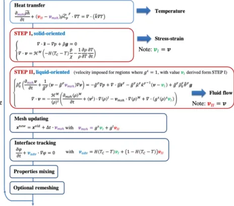
The detailed solution algorithm scheme together with the associated governing equations is illustrated hereunder in figure 1. Seven different stages are considered in one time increment ∆𝑡:
• 1st stage: Heat transfer. The monolithic energy conservation equation, written in the ALE
MCWASP XV 2020
IOP Conf. Series: Materials Science and Engineering 861 (2020) 012068
IOP Publishing doi:10.1088/1757-899X/861/1/012068
3
Table 1.Mixing properties in the heat transfer stage.
Notation Definition 𝜌ℎ̂ ℋ𝑀〈𝜌ℎ〉𝑀+ (1 − ℋ𝑀)𝜌 0𝐺ℎ𝐺 𝜌𝐶̂𝑝 𝐹 ℋ𝑀⟨𝜌⟩𝑙⟨𝐶 𝑝⟩ 𝑙 + (1 − ℋ𝑀)𝜌0𝐺∙ 𝐶 𝑝 0𝐺 𝑘̂ ℋ𝑀〈𝑘〉𝑀+ (1 − ℋ𝑀)𝑘 0 𝐺
where 〈𝜌ℎ〉𝑀is the volume enthalpy in the metal subdomain defined as 𝑔𝑙〈𝜌〉𝑙〈ℎ〉𝑙+ 𝑔𝑠〈𝜌〉𝑠〈ℎ〉𝑠. 𝑘̂ is the average conductivity equal to 𝑔𝑙〈𝑘〉𝑙+ 𝑔𝑠〈𝑘〉𝑠. ⟨𝜌⟩ , ⟨𝐶
𝑝⟩
, 〈ℎ〉, 〈𝑘〉 are respectively the intrinsic density, specific heat, specific enthalpy and thermal conductivity of the phase in metal. 𝜌0𝐺, 𝐶
𝑝 0𝐺, 𝑘0𝐺 and ℎ𝐺 are respectively the constant density, constant specific heat, constant thermal conductivity and specific enthalpy of gas. The energy transportation relative to the liquid phase is modelled by a convective term associated to liquid phase velocity. The nodal mesh velocity, 𝑣𝑚𝑠ℎ, is accounted for in the convective term, considering the mesh updating stage which will be further detailed. From this stage, the global temperature field, in both metal and gas subdomains, is computed.
• 2nd stage: STEP I solid-oriented solution. The classical momentum and mass conservation equations
of the solid mechanics in solidification processes [6] are extended in the level set framework, with the definition of the following mixed values:
Table 2.Mixing properties in the solid-oriented resolution stage.
Notation Definition
𝒔̂ ℋ𝑀𝒔𝑀+ (1 − ℋ𝑀)𝒔𝐺
𝜌̂ ℋ𝑀𝜌𝑀+ (1 − ℋ𝑀)𝜌0𝐺
where 𝒔𝑀, 𝜌𝑀, 𝒔𝐺, 𝜌𝐺are the stress tensor and average density respectively in metal and gas subdomains, considering the cast metal as a homogenized continuum. 𝑝 is the pressure field and 𝒈 is the constant gravity vector. Note that the average density of metal is assumed to be the intrinsic density of solid 〈𝜌〉𝑠 in the entire metal subdomain, to approximate the thermally induced solid deformation without solidification shrinkage effect. Besides, 𝐻(. ) is the standard Heaviside function, estimated at the temperature difference, 𝑇𝐶− 𝑇 . This function is introduced in the second mass conservation equation as an indicator relative to the use of the thermo-elastic-viscoplastic (TEVP) constitutive model for elements with average temperature lower than the critical temperature 𝑇𝐶. Otherwise the thermo-viscoplastic (TVP) model is used for temperature higher than 𝑇𝐶. In the present work 𝑇𝐶 is considered as equal to the solidus temperature to model the TEVP behaviour of material in the solid state. The TVP model is used for metal in the mushy or liquid state. Note that the mushy zone is considered as a homogenized non-Newtonian fluid, in which the strain rate sensitivity is continuously increasing with the liquid fraction, up to a pure Newtonian behaviour in the fully liquid state. Besides, an augmented fluid viscosity (including gas and liquid) is assumed in this stage similarly for numerical stability issues. Nonetheless, such approximation is reasonable as the fluid flow computation will be considered and computed in the next stage. Finally, from this stage, the velocity of the solid phase, 𝑣𝐼, is obtained. • 3rd stage: STEP II fluid-oriented solution. Momentum and mass conservation equations are written
in an ALE formulation, under a two phase approach with the use of the volume averaged method [8]. Similarly, expressions of the mixing values involved are resumed in the following table 3. 〈𝜌〉0𝑙, 〈𝜌〉𝑙, 〈𝒔〉𝑙, 𝜇𝑙, 〈𝜌〉𝑠 are respectively the intrinsic reference liquid density, intrinsic liquid density, intrinsic liquid stress tensor, liquid viscosity and intrinsic solid density. A fixed secondary dendrite arm spacing, 𝜆2, is considered in the estimation of the permeability value, 𝜅̂𝐹. 𝜇0𝐺 is the constant viscosity of gas, considered as a Newtonian and incompressible fluid. In addition, the Boussinesq approximation is assumed in fluid flow resolution. Note that interactions between solid and liquid phases in the mushy zone are modelled by the Darcy’s law with the solid velocity from previous stage 𝒗𝐼 as an entry.
MCWASP XV 2020
IOP Conf. Series: Materials Science and Engineering 861 (2020) 012068
IOP Publishing doi:10.1088/1757-899X/861/1/012068
4
Complementary to STEP I, the velocity of the liquid phase, calculated with the nominal liquid viscosity in STEP II, is denoted 𝒗𝐼𝐼.
Table 3.Mixing properties for the fluid-oriented solution.
Notation Definition 𝜌̂0𝐹 ℋ𝑀〈𝜌〉0𝑙 + (1 − ℋ𝑀)𝜌0𝐺 𝑔̂𝐹 ℋ𝑀𝑔𝑙+ (1 − ℋ𝑀) 𝑔𝒔̂𝐹 ℋ𝑀𝑔𝑙〈𝒔〉𝑙+ (1 − ℋ𝑀)𝒔𝐺 𝑔𝜌̂𝐹 ℋ𝑀𝑔𝑙〈𝜌〉𝑙+ (1 − ℋ𝑀)𝜌 0𝐺 𝜇̂𝐹 ℋ𝑀𝜇𝑙+ (1 − ℋ𝑀)𝜇 0𝐺 𝜅̂𝐹 𝜆22𝑔̂𝐹3⁄(180(1 − 𝑔̂𝐹)2)
• 4th stage: Mesh updating. The position of each mesh node is updated following an explicit scheme
with the mesh velocity, 𝒗𝑚𝑒𝑠ℎ. This velocity is equal to 𝒗𝐼 in the fully solidified regions and mushy domain. Based on this consideration, we assume that the energy transportation relative to the solid phase in the solid and mushy zones is achieved through the mesh updating process.
• 5th stage: Metal/gas interface tracking. The updating of the level set function permits interface
tracking. It is achieved by the convection-reinitialization scheme [9]. The advection velocity is defined according to the node temperature, considering that 𝒗𝑰𝑰 describes better the moving interface of liquid/gas and mush/gas, while 𝒗𝑰 describes better the interface solid/gas.
• 6th stage: Properties mixing. After the updating of the metal/gas interface, mixed material properties
over the artificial transition interface is subsequently updated according to the current level set function. • 7th stage: Adaptive remeshing. The final stage of the algorithm consists in an optional remeshing
process when the mesh quality is no longer satisfying.
MCWASP XV 2020
IOP Conf. Series: Materials Science and Engineering 861 (2020) 012068
IOP Publishing doi:10.1088/1757-899X/861/1/012068
5 3. Application to steel continuous casting
3.1. Model description
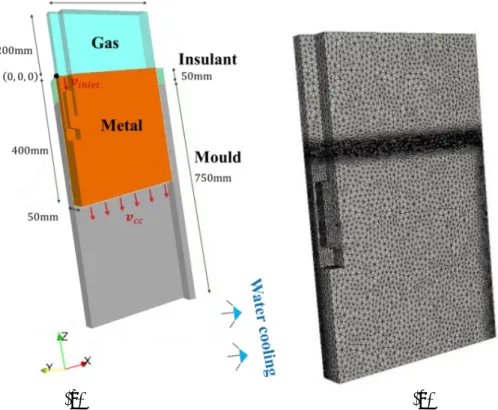
The partitioned algorithm is applied to a 3D CC test case for steel slabs. The initial configuration is given in figure 2(a) with the consideration of a submerged entry nozzle. Only a quarter of the full geometry is modelled considering the symmetry of the system. Heat is extracted from the metal through the lateral vertical surfaces. A constant flux is imposed along surfaces in contact with the mould and a convection type expression is defined along surfaces below the mould exit, in order to model the water cooling effect. An insulation zone is imposed in the vicinity of the meniscus so as to always maintain a liquid-gas interface in contact with the mould. The metal is supposed to slide along the surrounding vertical surfaces in contact with the mould as well as the two symmetry planes. A free velocity is considered on the upper surface in momentum resolution. The surrounding faces of the entry nozzle are defined as sticking. Velocity is imposed for both the liquid inlet surface (vertical velocity 𝒗𝑖𝑛𝑙𝑒𝑡 at the top of the entry nozzle) and the bottom surface (vertical casting velocity 𝒗𝑐𝑐). The same mechanical boundary conditions should be applied for both STEP I and STEP II. Nonetheless, the surrounding vertical surfaces in contact with the mould in STEP II, are assumed to be sticking, in order to reduce numerical instabilities due to the presence of the intensive nozzle jet in contact with the mould.
(a) (b)
Figure 2.Representation of (a) a schematic for the 3D CC model and (b) the initial mesh configuration. The initial mesh is defined in figure 2(b). The material properties of the steel grade used in simulation are artificially simplified and are resumed in table 4 together with simulation parameters. Note that solid and liquid densities are taken constant and equal except in the gravity term of STEP II, where the liquid density is governed by the Boussinesq approximation, 〈𝜌〉𝑙 = 〈𝜌〉
0
𝑙 (1 − 𝛽
𝑇𝑙(𝑇 − 𝑇𝑟𝑒𝑓)), and in the thermal dilatation term in STEP I, where the metal density is governed by a linear relation, 𝜌 = 𝜌0(1 − 𝛽𝑇𝑠(𝑇 − 𝑇𝑟𝑒𝑓)). Moreover, mechanical properties are detailed in a previous paper [4].
MCWASP XV 2020
IOP Conf. Series: Materials Science and Engineering 861 (2020) 012068
IOP Publishing doi:10.1088/1757-899X/861/1/012068
6
Table 4. Simulation and material parameters in the 3D CC test case.
Material parameters Symbol Value Unit
Solidus temperature 1431 °C
Liquidus temperature 1490.5 °C
Constant specific heat of solid and liquid 800 J · kg−1· °C−1
Constant specific heat of gas 1000 J · kg−1· °C−1
Latent heat 2.4 × 10⁵ J · kg−1
Reference temperature 𝑇𝑟𝑒𝑓 1490.5 °C
Reference liquid density 〈𝜌〉0𝑙 7000 kg · m−3
Reference metal density 𝜌0 7000 kg · m−3
Gas density 𝜌0𝐺 6000 kg · m−3
Liquid thermal dilatation coefficient 𝛽𝑇𝑙 1 × 10⁻⁴ °C−1
Solid thermal dilatation coefficient 𝛽𝑇𝑠 1 × 10⁻⁵ °C−1
Secondary dendrite arm spacing 𝜆2 5 × 10⁻⁴ m
Gas viscosity STEP I|STEP II 𝜇𝐺 1 | 1 × 10⁻¹ Pa · s
Liquid viscosity STEP I|STEP II 𝜇𝑙 1 | 5 × 10⁻³ Pa · s
Thermal conductivity in gas 0.1 W · m−1· °C−1
Thermal conductivity in solid 30 W · m−1· °C−1
Thermal conductivity in gas 30 W · m−1· °C−1
Simulation parameters
Casting temperature 1520.5 °C
Critical temperature 𝑇𝐶 1431 °C
External temperature 25 °C
Time step ∆𝑡 0.1 s
Casting velocity in the vertical direction 𝑣𝐶𝐶 -0.015 m · s−1
Liquid inlet velocity in the vertical direction 𝑣𝑖𝑛𝑙𝑒𝑡 -0.88 m · s−1
3.2. Results
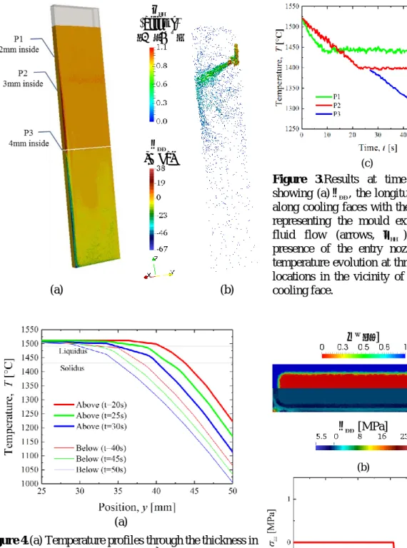
Figure 3(a) illustrates the results corresponding to time t = 80 s. The gas subdomain is shown in the upper part with the transparent grey region. The mould exit is shown with the white line. The longitudinal stress component 𝜎𝑧𝑧 along the external faces of the product is shown in figure 3(a),
revealing that the solid shell is under traction within the mould region while it is in compression below the mould exit, with maximum values reaching respectively 38 MPa and -67 MPa. The fluid flow is concurrently computed, represented by coloured arrows as shown in figure 3(b). It can be noticed that the intensive nozzle jet is mainly influent in the mould region, preventing the formation of the mushy zone due to heat transport. Figure 3(c) shows the temperature evolution at three predefined locations, at positions (373, 0, -200), (372, 0, -400) and (371, 0, -800) with unit in mm respectively for position 1, 2 and 3. All positions are in the mould region, in the vicinity of the narrow face. After 50 s of casting process, the steady-state regime has been reached within the mould region since position 3 is located exactly in the transversal cross section at the mould exit.
Temperature profiles computed over the half thickness of 25 mm (near the wide cooling face) at the narrow symmetry plane are drawn in figure 4(a) at three different times and two different positions respectively at height 𝑧 = −0.6 m above the mould exit (thick lines) and 𝑧 = −1.0 m below the mould exit (thin lines). It can be seen that in the mould region, due to the constant heat flux imposed on the wide cooling face, the cooling rate of the solid shell is higher at the surface than in subsurface. As a consequence, a tensile stress is found in surface. In the secondary cooling region where the cooling is
MCWASP XV 2020
IOP Conf. Series: Materials Science and Engineering 861 (2020) 012068
IOP Publishing doi:10.1088/1757-899X/861/1/012068
7
less intense, expressed by the Fourier-type boundary condition, the cooling rate becomes higher in subsurface than in surface. This explains why a compressive stress is found in surface.
𝑣𝐼𝐼 (arrows) [m · s−1]
𝜎𝑧𝑧
[MPa] (c)
Figure 3.Results at time 𝑡 = 80 s , showing (a) 𝜎𝑧𝑧, the longitudinal stress along cooling faces with the white line representing the mould exit; (b) The fluid flow (arrows, 𝒗𝐼𝐼 ) with the presence of the entry nozzle; (c) 𝑇 , temperature evolution at three different locations in the vicinity of the narrow cooling face. (a) (b) 𝑔𝑠 [−] 𝜎𝑧𝑧 [MPa] (b) (a)
Figure 4.(a) Temperature profiles through the thickness in the transverse symmetry plane (𝑦, 𝑧) at three different times and two different positions above (thick lines) and below (thin lines) the mould exit; (b) 𝑔𝑠 and 𝜎𝑧𝑧 , respectively the solid fraction and the stress component in 𝑧 direction, shown over the transverse cross section at mould exit at time 80 s; (c) 𝜎𝑧𝑧 stress profile through the
MCWASP XV 2020
IOP Conf. Series: Materials Science and Engineering 861 (2020) 012068
IOP Publishing doi:10.1088/1757-899X/861/1/012068
8
Finally, the solid fraction and the stress component in 𝑧 direction (𝜎𝑧𝑧) are plotted over the cross section at the mould exit (figure 4(b)), showing a solid shell with thickness between 10 and 15 mm. It can be seen that the external face is submitted to a global tensile stress with the maximum value of 23 MPa located at the corner of the cooling faces while the solidification front undergoes smaller compression stress. It should be mentioned that this maximum predicted value might be unrealistic as the cooling faces are highly constrained (the velocity along faces is imposed to be vertical). The 𝜎𝑧𝑧 stress profile through the thickness in the transverse symmetry plane is drawn in figure 4(c), with the position 𝑥 varying from the centre to the wide cooling face. It can be seen that the vertical stress along the external face has already shifted, from tensile to slightly compressive. Nonetheless, a considerable part of the solid shell near the cooling face is still under traction. Inside the solid shell, compression stresses are found, expressing the necessary mechanical equilibrium along the vertical direction. Finally, it is interesting to note that the predicted stress levels at this specific position are consistent with the flow stress measurement of 1 – 5 MPa, made on solidifying shells by Hiebler et al. [10].
4. Conclusions
A new algorithm of concurrent and coupled resolution of fluid flow and solid deformation has been developed for both IC and CC processes. The algorithm consists of a partitioned solution strategy, solving at each time increment a solid-oriented solution and a fluid-oriented solution. A global non steady-state approach is adapted in view of the CC process. All solutions are formulated with the finite element method, using a level set tracking of the moving interface between the solidifying metal subdomain and the gas subdomain. This algorithm has been applied to a 3D CC process. Simulation gives promising results, in which the fluid flow in the bulk liquid or mushy zone and stress formed in the solid regions are concomitantly computed.
The main perspectives of this work are twofold. Firstly, coupling this new algorithm with macrosegregation modelling would allow demonstrating the influence of the solid deformation on the central macrosegregation in CC processes. Secondly, the coupling with equiaxed grain motion would provide access to enhanced predictions of macrosegregation due to thermosolutal convection, shrinkage flow and transport of equiaxed grains.
Acknowledgements
This work is funded by the European Space Agency under project CCEMLCC (AO-2004-017 contract 4200020277) as well as by industrial partners ArcelorMittal Maizières Research, INDUSTEEL France and APERAM ALLOYS IMPHY.
References
[1] Fachinotti V D, Le Corre S, Triolet N, Bobadilla M and Bellet M 2006 Int. J. Numer. Meth. Eng. 67 1341-84
[2] Ludwig A, Vakhrushev A, Wu M, Holzmann T and Kharicha A 2015 T. Indian I. Metals 68 6 1087-94
[3] Kajitani T, Drezet J M and Rappaz M 2001 Metall. Mater. Trans. B 32 1479-91
[4] Zhang S, Guillemot G, Gandin Ch A and Bellet M 2019 Comput. Method. Appl. M. 356 294-324 [5] Bellet M and Heinrich A 2004 ISIJ Int. 44 10 1686-95
[6] Bellet M and Fachinotti V D 2004 Comput. Method. Appl. M. 193 4355-81 [7] Saad A, Gandin Ch A and Bellet M 2015 Comput. Mater. 99 221-31 [8] Ni J and Beckermann C 1991 Metall. Mater. Trans. B 22 349-61
[9] Shakoor M, Scholtes B, Bouchard P O and Bernacki M 2015 Appl. Math. Model. 39 7291-302 [10] Hiebler H, Zirngast J, Bernhard C and Wolf M M 1994 Steelmaking Conference Proceedings 77