Science Arts & Métiers (SAM)
is an open access repository that collects the work of Arts et Métiers Institute of
Technology researchers and makes it freely available over the web where possible.
This is an author-deposited version published in:
https://sam.ensam.eu
Handle ID: .
http://hdl.handle.net/10985/15178
To cite this version :
Faissal CHEGDANI, Mohamed EL MANSORI - Mechanics of material removal when cutting
natural fiber reinforced thermoplastic composites - Polymer Testing - Vol. 67, p.275-283 - 2018
Any correspondence concerning this service should be sent to the repository
Administrator :
[email protected]
thermoplastic composites
Faissal Chegdani
∗, Mohamed El Mansori
Arts et Métiers ParisTech, MSMP/EA7350, Rue Saint Dominique, BP508, 51006, Châlons-en-Champagne, France
A R T I C L E I N F O Keywords: Naturalfibers Thermoplastic composites Machining process Mechanical testing Chip formation Multiscale surface analysis
A B S T R A C T
This paper aims to study the machinability of naturalfiber reinforced thermoplastic composites by investigating the mechanics of chip formation and the multiscale cut surface's quality induced by the orthogonal cutting process. Unidirectionalflax fibers reinforced polypropylene (UDF/PP) composite has been tested by orthogonal cutting experiments. Mechanical tensile and shear tests have been conducted on UDF/PP specimens to relate the mechanical behavior to the cutting behavior.
Results show that UDF/PP composites produce a continuous chip at all the considered cutting conditions. This is inherently related to the specific mechanical behavior of flax fibers inside the thermoplastic matrix under cutting solicitations. The cutting behavior induces a consequent surface damages in the form of debonding zones and uncutfiber extremities. Results demonstrate that the cutting depth has the most significant influence on the machinability after sorting the pertinent scales of the cut surface using the multiscale surface analysis approach.
1. Introduction
The use of naturalfiber reinforced plastics (NFRP) composites is becoming an industrial reality, especially in automotive and aerospace industries. NFRP composites are becoming a viable alternative to syn-theticfiber composites in many industrial applications that not require high structural performances. This strong industrial demand for NFRP materials is due to the mechanical, economic and ecological benefits that provide natural fibers for sustainable development, particularly plantfibers [1–4]. NFRP composites have aroused the interest of sci-entists to understand and optimize their manufacturing processes [5–7] and also to investigate their biodegradable behavior [8]. However, the finishing processes have not been well investigated even if few em-pirical works show that the cutting behavior of plantfiber composites is not the same like that of syntheticfibers [9–12].
Standard machining processes, such as milling, are still the best suitable for machining polymeric composites since they induce low levels of damage in the machined surface [13]. For these reasons, many work was conducted by the authors in order to understand the behavior of plant fibers inside the composite during the industrial machining process of profile milling [14–17]. These studies show that, effectively, the behavior of plantfibers is different from that of synthetic fibers and this is due to their complex and multiscale cellulosic structure around thefiber axis [18]. This structure induces a high transversal elasticity to the plantfiber inside the composite and gives them the ability to deform
easily, which makes there shearing difficult during the cutting process. The previous author's works show also that investigating the machined surfaces of NFRP composites requires the selection of the relevant scales that allow the discrimination of both material and process parameters effects. Indeed, unlike glass fibers, plant fibers present a scale effect since their mechanical properties depends on the mechanical scale used for the analysis as demonstrated in Ref. [19].
Nowadays, the use of naturalfiber composites is focused also on structural applications that require high mechanical performances, especially long plantfiber reinforced polymer composites [4,20–22]. In the context of sustainable development and circular economy, the in-terest is oriented toward the thermoplastic composites because ther-moplastic matrices are recyclable. Thus, since the mechanical proper-ties of thermoplastic composites are lower than that of thermoset composites, it is necessary to understand the relationship between the mechanical properties of plantfibers reinforced thermoplastic compo-sites and their mechanics of cutting in order to optimize their manu-facturing processes and avoid mechanical cutting-induced damages.
In this paper, the fundamental process of orthogonal cutting is conducted on unidirectionalflax fibers reinforced polypropylene (UDF/ PP) composites in order to investigate the chip formation mechanisms. Mechanical tensile and shear tests are realized on the same material for better comprehension of the cutting process from a mechanical point of view.
The induced machined surfaces are evaluated by scanning electron
∗Corresponding author.
E-mail address:[email protected](F. Chegdani).
microscopy (SEM). Then, cutting forces are plotted to show the influ-ence of each process parameter on the cutting operation. The machined surfaces topography is investigated by a multiscale approach based on discrete wavelet transform. Statistical analysis of variance (ANOVA) is realized at the end to quantify the contribution rate of each process parameter on the multiscale roughness of the machined surfaces.
2. Material and methods
2.1. Unidirectionalflax/polypropylene composite workpieces
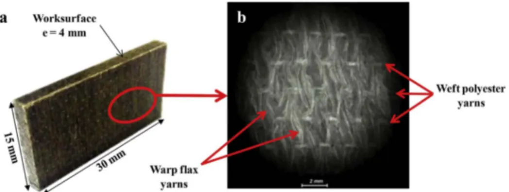
Unidirectionalflax fiber composites used in this study (Fig. 1(a)) are supplied by “Composite Evolution - UK”. The composite structure is produced by unidirectional longflax fibers (UDF) and polypropylene matrix (PP) as continuous warpflax yarns. Synthetic weft yarns assure the unidirectionality of the composite. Theflax/PP composition is 40% vt of UDF and 60% vt of PP (approximately 50% wt for each con-stituent). The warp yarn diameter is approximately 1 mm (Fig. 1(b)). The weft yarns are composed of co-polyamide/polyester co-spun. The incidence of weft yarns is 1 yarn per 2.5 mm, giving an areal weight of 14 g/m2(approximately 5% of the total fabric).Table 1summarizes the mechanical properties offlax fibers and PP matrix. The supplier pro-vides these technical data.
Inside eachflax yarn, the distribution of the elementary flax fibers is random in terms of geometry (cylindrical to polygonal), size (10μm–20 μm) and location as shown inFig. 2(a). Some elementary fibers are thus gathered into a bundle, which called technical fiber (Fig. 2(b)), and other elementaryfibers are isolated in the matrix. This random distribution can have an influence on characterizing the ma-chined surfaces of UDF/PP composites.
2.2. Mechanical tests
Tensile tests (Fig. 3(a)) have been performed on Instron 4482 Uni-versal testing machine according to ISO-527 standard. The in-situ strain of the tested UDF/PP samples has been recorded by Instron 2630-100 Clip-on extensometer. Shear tests have been realized using the Iosipescu method showed inFig. 3(b) and described in Refs. [23,24]. The in-situ strain of the Iosipescu specimens has been measured by VPG Tee Ro-settes gages (Model CEA-06-032WT). Tensile and shear tests have been realized for different displacement speeds.
2.3. Cutting tests
Orthogonal cutting experiments, as shown inFig. 4, were conducted on a shaper machine (model GSP-EL 136). The machine is of maximum power of 5222 W, maximum stroke of 650 mm and maximum speed of 100 m min−1. Three cutting inserts supplied by "Sandvik Coromant– FR" (A4F3, A4BQ and A4BS) have a unique cutting geometry with 20° rake angle and 7° clearance angle. The main objective for adding coating film is to increase the cutting edge radius as shown inTable 2.
Tests were performed under dry conditions. The specimen was clamped manually in the machine bearing between two hard steel plates as shown inFig. 4. Edge trimming of the composite material results from the relative motion between the tool,fixed to the moving saddle, and the specimen. Thefibers orientation is always perpendi-cular to the cutting direction in order to consider the worst cutting condition. For getting reliable results, each test was repeated three times under identical conditions and with a new cutting insert at each time. Table 3 summarizes the cutting conditions considered in this study.
2.4. Experimental measurements
To highlight the in-situ chip formation mechanisms during cutting, a fast-camera (FASTCAM SA5 CCD) was used for recording optical frames at an acquisition rate of 20,000 fps. The in-situ cutting forces have been recorded using a piezoelectric Kistler dynamometer (model 9255B), connected to a multichannel charge amplifier (model 5019 B131) and a data acquisition board. The considered cutting force is the measured component that is parallel to the cutting direction.
Microscopic observations of UDF/PP machined surfaces state were made by scanning electron microscope (SEM) (JSM–5510LV) at low vacuum mode. Typical representative surface morphology as induced by machining of each experimental configuration was considered for the microscopic analysis. Geometrical and superficial variations of each workpiece samples have been measured atfive locations using a 2D Surfascan stylus profilometer according to the ISO-4287 standard. The tip radius of the diamond stylus is 2μm. The surface profile on each specimen was taken along the machining direction over a sampling length of 8μm. The evaluation length is 16.8 mm and a cut-off of 0.8 mm is used to apply the multiscale decomposition of the overall topography signal by discrete wavelet transform [25].
3. Results and discussion
3.1. Mechanical behavior of UDF/PP specimens
Fig. 5presents both tensile and shear behaviors of UDF/PP speci-mens for different deformation speeds. Tensile behavior shows two linear parts (Fig. 5(a)), thefirst part corresponds to the contribution of thefibrous reinforcement and the polymer matrix. By reaching a stress
Fig. 1. a) UDF/PP workpiece. b) Fibrous structure offlax fibers reinforcement.
Table 1
Mechanical propertiesflax fibers and PP matrix used in composite workpieces. Flaxfiber PP matrix Tensile modulus (GPa) 50 0.93 Tensile strength (MPa) 500 29.5
Maximum strain 2% 14%
value of 30 MPa (i.e. the tensile strength of PP matrix), the behavior remains linear but the stiffness decreases due to debonding between fibers and matrix. At a stress value of approximately 100 MPa, the be-havior becomes nonlinear, corresponding to a plastic bebe-havior until break (Fig. 6(a)). Thus, the UDF/PP composites have a linear tensile behavior with ductile break and the effect of displacement speed is only apparent on the plastic zone that increases the strain at break.
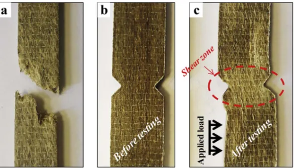
The shear curves of UDF/PP specimens show an elastoplastic be-havior (Fig. 5(b)). The increasing of displacement speed increases the shear modulus but does not have an influence on the ductile shear behavior. It's important to mention that the break has not been reached by the Iosipescu test. Indeed, throughout the loading, thefibers follow the movement of shear and deform transversely with a debonding be-tween thefibers and matrix that is observed during the deformation at the shear zone (Fig. 6(c)). Thefibers continue to deform until be mainly under tensile solicitation.
3.2. Chip formation of UDF/PP composites
Fig. 7shows the in-situ chip morphology for different cutting con-ditions. Both cutting speed and depth influence the chip curling. Cut-ting UDF/PP samples with low cutCut-ting speed and low cutCut-ting depth favors the chip curling (Fig. 7(a)). Increasing these two parameters reduces the chip curling due to the increase of plastic deformation re-sistance in the UDF/PP workpieces (Fig. 7(i)). Reducing the chip curling can have an impact on the tribological contact behavior between the cutting tool and the NFRP material. Indeed, when the chip curling is reduced, there is more contact between the removed chip and the tool rake face, which increases the friction at this contact area. Therefore, reducing the chip curling can accelerate the tool wear.
The fast-cam images ofFig. 7show that, regardless of cutting speed and depth at the considered values range, the UDF/PP composite gen-erates a continuous long chip on all the cutting length for all the cutting conditions. Thisfinding is specifically different from that of synthetic
fiber composites as glass or carbon fibers. Indeed, the chip formation of syntheticfiber composites depends on the matrix nature. For thermoset composites, the removed chip is often discontinuous or powdery [26–35]. This is inherently related to the mechanical behavior of the thermoset composite during the cutting solicitations. This mechanical behavior is similar to shearing solicitations that show a brittle behavior
Fig. 2. a) SEM image of theflax fibers distribution in the composite. b) SEM image of the technical fiber.
Fig. 3. a) ISO-527 tensile test. b) Iosipescu shear test.
Fig. 4. Experimental setup of the orthogonal cutting tests.
Table 2
Coating characteristics of each cutting insert.
Reference A4F3 A4BQ A4BS
Substrate WC WC
Coating process – Multilayer CVD Coating composition – Diamond sp3
Hardness (HV) 1600 10000 Coating thickness (μm) – 9± 1 14± 2
using Iosipescu shear tests [24,36]. On the other side, the chip forma-tion of syntheticfiber reinforced thermoplastic composites tend to be continuous [37–40], except for high cutting speed where the removed chip becomes discontinuous [40]. This demonstrates that the matrix nature has a significant role in the chip formation. Thermosetting ma-trix is brittle and its cutting mechanism is dominated by fracture, while thermoplastic matrix has the capability to withstand large elastic and plastic strains. However, the continuous-to-discontinuous chip transi-tion has been reported to occur for general syntheticfiber composites when thefibers orientation is above 75° and near to 90°. This is because of the severity of interlaminar shear. This transition is marked by the change in direction of the force parallel to thefibers from tensile to compressive, which makes thefibers shearing more difficult [41,42].
In the case of UDF/PP composites, the mechanical behaviors are different as explained in Section3.1. Flax fiber composites show a ductile behavior at both tensile and shear tests. At Iosipescu shear test, which the solicitations can be similar to those of the cutting operation, the ductile behavior is followed by a transverse deformation of flax fibers toward the shear direction. This is because flax fibers have a high transverseflexibility due to the microstructure of cellulosic microfibrils that are oriented along thefiber axis [17,18]. Theflax stiffness is then intensive on thefiber axis direction and the transverse stiffness is sig-nificantly low. The cutting contact stiffness is thus low and flax fibers follow the deformation movement of the PP matrix during the cutting operation. Then, the cohesion betweenfibers and matrix can withstand the stresses of the cutting operation and, consequently, the removed chip remains continuous.
3.3. Cutting forces
Fig. 8presents the cutting forces on the orthogonal cutting direc-tion. It can be seen a drastic increasing of cutting force by cutting depth increase. Increasing the cutting speed increases the cutting forces. However, increasing either the cutting depth or the cutting edge radius reduces the impact of the cutting speed. Therefore, the effect of the cutting speed becomes insignificant when cutting by an edge radius of 27μm with 500 μm of cutting depth.
Increasing either the cutting depth or the cutting speed increases the
cutting forces by raising the material removal rate. However, the cut-ting depth effect is more significant because it increases the chip thickness that enhances the material resistance when cutting. On the other side, the cutting speed has a double effect. Indeed, increasing the cutting speed increases the material removal rate and then the cutting forces. Nevertheless, cutting speed growing induces high temperatures at the cutting zone that makes the material softer and leads to reduce the cutting forces. Therefore, the thermal effect compensates the ma-terial removal rate effect. This thermal effect is also induced by the cutting depth and the edge radius of the cutting tool. In fact, increasing the cutting depth increases plastic deformations when cutting and, then, the material temperature is growing due to high plastic de-formation rates. The cutting edge radius increase leads to raise the cutting contact area which favors the temperature increase at the cut-ting zone due to friction. All these physical phenomena can explain why the effect of cutting speed is reduced at both high cutting depth and edge radius.
Cutting forces analysis shows the significance of the cutting depth to control the machinability offlax fiber composites because increasing the cutting depth by 200μm can considerably increase the cutting force and, consequently, this will cause bulk and surface damages. Next section deals with the study of these damages.
3.4. Microscopic quality of machined surfaces
Fig. 9presents the SEM images of machined surfaces at the same cutting speed (80 m/min) for different cutting conditions. Cutting UDF/ PP composites with 12μm of edge radius and 100 μm of cutting depth generates efficient fibers shearing because flax fibers cross-sections can be observed inFig. 9(a). By increasing the cutting edge radius, plastic deformation offlax fibers cross-sections can be noticed inFig. 9(d) and
(g). Indeed,fibers cross-sections shape is changed when growing from higher to lower tool sharpness. Increasing the cutting edge radius in-creases the fibers cross-sections diameter by plastic deformation of these latter. On the other side, increasing the cutting depth deteriorates thefibers shearing where flax fibers are transversely deformed toward the cutting direction before being sheared. This induced some uncut fibers extremities that remain on the machined surface (Fig. 9(c)). In-creasing the depth of cut increases not only the uncutfiber extremities but also the debonding zones between elementaryfibers and PP matrix, especially when it is associated with a cutting edge radius increase (Fig. 9(i)).
The uncutfiber extremities are the specific phenomena in the case of machining plantfiber composites because of the transverse flexibility issue of plantfibers when being in contact with the cutting tool as demonstrated in the previous milling operation work [15–17], espe-cially when increasing the cutting edge radius [17]. Moreover, the high cutting forces induced by increasing the cutting depth (Fig. 8) causes more failure of the interfaces between elementaryflax fibers and PP
Table 3
Process parameters used for the orthogonal cutting tests. Cutting inserts Cutting speed
(m/min) Depth of cut (μm) A4F3 A4BQ A4BS 12 20 32 50 80 100 300 500
Fig. 5. A typical behavior curves of UDF/PP composites at different displacement speeds. a) Tensile test. b) Iosipescu shear test.
Fig. 6. a) Tensile specimen after break. b) Iosipescu specimen before shear test. c) Iosipescu specimen after shear test.
matrix and this will reduce the cutting contact stiffness. Consequently, more deformation will be produced when the cutting contact which makes difficult the fiber shearing during the cutting operation. On an-other side, and unlike syntheticfibers of glass or carbon, natural fibers are known as composite materials of cellulose microfibrils embedded in amorphous natural polymers of hemicellulose and lignin [14,18]. The amorphous component of naturalfibers allows plastic deformations of these latter, especially when increasing the temperature during the cutting process since thefibers will be softer and easily able to deform.
3.5. Multiscale surface roughness of machined surfaces
The multiscale discrete wavelet transform (DWT) approach [15,17] consists on decomposing the global topographic signal through a series
of high-pass and low-pass filters to analyze the high and low fre-quencies [43]. Since the high frequencies correspond to the micro-roughness and the low frequencies correspond to the waviness, it can be obtained, after reconstruction, the multiscale spectrum that reveals the mean arithmetic roughness “Ma(i)" at each scale “i” of the decom-position [44].
Fig. 10presents the evolution of the multiscale spectrums at cutting speed V = 20 m/min for the different cutting edge radius. Globally, the roughness increases by the scale increasing. The multiscale approach can discriminate the cutting depth effect at the mesoscopic scales be-tween 50μm and 1 mm. Then, the relevant scales are those of the fi-brous structure size inside the composite (i.e. from technicalfiber size [∼50 μm] to fiber yarn size [∼1 mm]). This finding corresponds to the conclusions obtained by profile milling process [15–17]. However, for
Fig. 8. Induced cutting forces during cutting operations for all cutting conditions.
Fig. 9. SEM images of microscopic surfaces quality for different cutting edge radius (rε) and cutting depth (ap).
the orthogonal cutting process, it can be seen inFig. 10that increasing the cutting edge radius reduces the relevant scales toward the macro-scopic scales by increasing the cutting contact area as demonstrated in Ref. [45].
Fig. 11shows the effect of cutting speed on the multiscale surface
roughness spectrums for the cutting edge radius rε= 27μm. Increasing
the cutting speed increases the relevant scales range that allow the discrimination of the cutting speed effect. At the relevant scales, the multiscale spectrums ofFig. 11show that the effect of cutting speed is more obvious at the low cutting depth. Increasing the cutting speed decreases the surface roughness except for a cutting depth of 500μm where the cutting speed is not highly significant. Indeed, increasing the cutting speed increases the shear modulus (Fig. 5(b)) which will in-crease the contact stiffness and, then, the shearing efficiency. 3.6. Multiscale contribution rate of process parameters to the surface quality
To quantify the contribution of the studied process parameters, ANOVA [46,47] of input variables influence has been performed at
each multiscale response of surface quality (i.e. at each scale“i” of the decomposition) using XLSTAT software. The contribution ratio of each “α” factor (Cα) was calculated with the Fisher criterion test (F(α)) at the
correlation coefficient (R2) confidence [
46,48]. Eq.(1)can define the
contribution ratio of each factor. More explanations about this statis-tical technique are in Ref. [14].
= ∑ × C F α F α R ( ) ( ) α α 2 (1)
Fig. 12presents the contribution rate of each process parameter at each analysis scale. It can be seen the low contribution of the cutting edge radius regarding the other parameters until the macroscopic scales. The behavior of the multiscale contribution rate confirms the previous results. Indeed,Fig. 12shows the significant impact of cutting
depth at the relevant scale (i.e. mesoscopic scale) identified in Section
3.5. At macroscopic scale, the random distribution of technicalfibers seen inFig. 2influences the contribution of the process parameters and
increases the interactions between them. Then, the interactions have the predominant contribution.
4. Conclusions
Orthogonal cutting process has been conducted on unidirectional flax fiber reinforced polypropylene (UDF/PP) composites in order to investigate the mechanics of material removal by realizing mechanical tests on the same material. The resulting machined surfaces have been evaluated by SEM observations and multiscale topographic analysis. The following conclusions can be drawn:
•
Even ifflax fibers are oriented perpendicularly to the cutting di-rection, UDF/PP composites show a long continuous chip during the orthogonal cutting process at a large range of cutting speed andFig. 10. Multiscale surface roughness spectrums drawn at each cutting depth for the different cutting edges radius at cutting speed V = 20 m/min.
Fig. 11. Multiscale surface roughness spectrums drawn at each cutting depth for different cutting speeds at the cutting edge radius rε= 27μm.
depth values. This chip behavior is different from that of synthetic thermoplastic composites, which have a discontinuous chip at dry and high loading cutting conditions.
•
The specific cutting behavior of UDF/PP composites is related to the mechanical ductile behavior of the thermoplastic matrix combined with the high transverse elasticity offlax fibers that have also a ductile behavior unlike glass or carbonfibers.•
The cutting depth has the greatest influence on machined surface state. Increasing the cutting depth increases the cutting forces and, then, the surface damages in form of debonding zones, uncutfibers extremities and plastic deformation offlax fibers on the machined surface. The effect of cutting speed is significantly reduced due to the thermal effect induced by friction and plastic deformation.•
Analyzing the machined surfaces offlax fiber composites requires the selection of the relevant scales. The effects of both cutting depth and cutting edge radius are more obvious at the scales that corre-spond to theflax fibrous structure size inside the composite. ANOVA analysis confirms that the cutting depth is strongly the most influent parameter on the machined surface quality at the relevant scales. AcknowledgementsThe authors acknowledge the urban community of Châlons-en-Champagne (Cités en Châlons-en-Champagne) for theirfinancial support.
References
[1] D.B. Dittenber, H.V.S. GangaRao, Critical review of recent publications on use of natural composites in infrastructure, Compos. Part A Appl. Sci. Manuf 43 (2012) 1419–1429,http://dx.doi.org/10.1016/j.compositesa.2011.11.019.
[2] O. Faruk, A.K. Bledzki, H.-P. Fink, M. Sain, Biocomposites reinforced with natural fibers: 2000–2010, Prog. Polym. Sci. 37 (2012) 1552–1596,http://dx.doi.org/10. 1016/j.progpolymsci.2012.04.003.
[3] A. Lefeuvre, A. Bourmaud, C. Morvan, C. Baley, Tensile properties of elementary fibres of flax and glass: analysis of reproducibility and scattering, Mater. Lett. 130 (2014) 289–291,http://dx.doi.org/10.1016/j.matlet.2014.05.115.
[4] D.U. Shah, Developing plantfibre composites for structural applications by opti-mising composite parameters: a critical review, J. Mater. Sci. 48 (2013) 6083–6107,
http://dx.doi.org/10.1007/s10853-013-7458-7.
[5] K. Sam-Jung, M. Jin-Bok, K. Gue-Hyun, kHa Chang-Si, Mechanical properties of polypropylene/naturalfiber composites: comparison of wood fiber and cotton fiber, Polym. Test. 27 (2008) 801–806,http://dx.doi.org/10.1016/J.POLYMERTESTING. 2008.06.002.
[6] M. Nasihatgozar, V. Daghigh, T. E Lacy Jr., H. Daghigh, K. Nikbin, A. Simoneau, Mechanical characterization of novel latania naturalfiber reinforced PP/EPDM composites, Polym. Test. 56 (2016) 321–328,http://dx.doi.org/10.1016/J. POLYMERTESTING.2016.10.016.
[7] A. Shalwan, B.F. Yousif, State of Art: mechanical and tribological behaviour of polymeric composites based on naturalfibres, Mater. Des. 48 (2013) 14–24,http:// dx.doi.org/10.1016/j.matdes.2012.07.014.
[8] A.G. Michael, M.G. Luke, A.K. John, G.L. John, L.H. Clement, Mechanical and biodegradation performance of short naturalfibre polyhydroxybutyrate composites, Polym. Test. 32 (2013) 1603–1611,http://dx.doi.org/10.1016/J.
POLYMERTESTING.2013.10.011.
[9] P.N.E. Naveen, M. Yasaswi, R.V. Prasad, Experimental investigation of drilling parameters on composite materials, J. Mech. Civ. Eng 2 (2012) 30–37. [10] L.M.P. Durão, D.J.S. Gonçalves, J.M.R.S. Tavares, V.H.C. de Albuquerque,
T.H. Panzera, L.J. Silva, a. A. Vieira, a. P.M. Baptista, Drilling delamination out-comes on glass and sisal reinforced plastics, Mater. Sci. Forum 730–732 (2012) 301–306,http://dx.doi.org/10.4028/www.scientific.net/MSF.730-732.301. [11] P.K. Bajpai, K. Debnath, I. Singh, Hole making in naturalfiber-reinforced polylactic
acid laminates, J. Thermoplast. Compos. Mater. 30 (2017) 30–46,http://dx.doi. org/10.1177/0892705715575094.
[12] G.D. Babu, K.S. Babu, B.U.M. Gowd, Effect of machining parameters on milled naturalfiber-reinforced plastic composites, J. Adv. Mech. Eng (2013) 1–12,http:// dx.doi.org/10.7726/jame.2013.1001.
[13] A. Codolini, Q.M. Li, A. Wilkinson, Influence of machining process on the me-chanical behaviour of injection-moulded specimens of talc-filled Polypropylene, Polym. Test 62 (2017) 342–347,http://dx.doi.org/10.1016/J.POLYMERTESTING. 2017.07.018.
[14] F. Chegdani, S. Mezghani, M. El Mansori, Correlation between mechanical scales
and analysis scales of topographic signals under milling process of naturalfibre composites, J. Compos. Mater. 51 (2017) 2743–2756,http://dx.doi.org/10.1177/ 0021998316676625.
[15] F. Chegdani, S. Mezghani, M. El Mansori, A. Mkaddem, Fiber type effect on tribo-logical behavior when cutting naturalfiber reinforced plastics, Wear 332–333 (2015) 772–779,http://dx.doi.org/10.1016/j.wear.2014.12.039.
[16] F. Chegdani, S. Mezghani, M. El Mansori, On the multiscale tribological signatures of the tool helix angle in profile milling of woven flax fiber composites, Tribol. Int. 100 (2016) 132–140,http://dx.doi.org/10.1016/j.triboint.2015.12.014. [17] F. Chegdani, S. Mezghani, M. El Mansori, Experimental study of coated tools effects
in dry cutting of naturalfiber reinforced plastics, Surf. Coatings Technol 284 (2015) 264–272,http://dx.doi.org/10.1016/j.surfcoat.2015.06.083.
[18] C. Baley, Analysis of theflax fibres tensile behaviour and analysis of the tensile stiffness increase, Compos. - Part A Appl. Sci. Manuf 33 (2002) 939–948,http://dx. doi.org/10.1016/S1359-835X(02)00040-4.
[19] F. Chegdani, M. El Mansori, S. Mezghani, A. Montagne, Scale effect on tribo-me-chanical behavior of vegetalfibers in reinforced bio-composite materials, Compos. Sci. Technol. 150 (2017) 87–94,http://dx.doi.org/10.1016/j.compscitech.2017.07. 012.
[20] K. Moussa, M. Valérie, D. Arnaud, A. Boussad, A. Fazilay, G. Ying Qiao, V. François, R. Frédéric, Flax/Acrodur® sandwich panel : an innovative eco-material for auto-motive applications, JEC Compos. Mag 51 (2014) 54–59.
[21] M. Khalfallah, B. Abbès, F. Abbès, Y.Q. Guo, V. Marcel, A. Duval, F. Vanfleteren, F. Rousseau, Innovativeflax tapes reinforced Acrodur biocomposites: a new alter-native for automotive applications, Mater. Des. 64 (2014) 116–126,http://dx.doi. org/10.1016/j.matdes.2014.07.029.
[22] G. Koronis, A. Silva, M. Fontul, Green composites: a review of adequate materials for automotive applications, Compos. Part B Eng 44 (2013) 120–127,http://dx.doi. org/10.1016/j.compositesb.2012.07.004.
[23] F. Pierron, Saint-venant effects in the Iosipescu specimen, J. Compos. Mater. 32 (1998) 1986–2015,http://dx.doi.org/10.1177/002199839803202201. [24] P. Ghidossi, M. El Mansori, F. Pierron, Ge machining effects on the failure of
polymer matrix composite coupons, Compos. Part A Appl. Sci. Manuf 35 (2004) 989–999,http://dx.doi.org/10.1016/j.compositesa.2004.01.015.
[25] X. Chen, J. Raja, S. Simanapalli, Multi-scale analysis of engineering surfaces, Int. J. Mach. Tool Manufact. 35 (1995) 231–238, http://dx.doi.org/10.1016/0890-6955(94)P2377-R.
[26] A. Ben Soussia, A. Mkaddem, M. El Mansori, Rigorous treatment of dry cutting of FRP– interface consumption concept: a review, Int. J. Mech. Sci. 83 (2014) 1–29,
http://dx.doi.org/10.1016/j.ijmecsci.2014.03.017.
[27] N. Bhatnagar, N. Ramakrishnan, N.K. Naik, R. Komanduri, On the machining of fiber reinforced plastic (FRP) composite laminates, Int. J. Mach. Tool Manufact. 35 (1995) 701–716,http://dx.doi.org/10.1016/0890-6955(95)93039-9.
[28] A. Koplev, A. Lystrup, T. Vorm, The cutting process, chips, and cutting forces in machining CFRP, Composites 14 (1983) 371–376,http://dx.doi.org/10.1016/ 0010-4361(83)90157-X.
[29] M. Zimmerman, L. Heberger, F. Schneider, C. Effgen, J.C. Aurich, Investigation of chip formation and workpiece load when machining carbon-fiber-reinforced-polymer (CFRP), Procedia Manuf 6 (2016) 124–131,http://dx.doi.org/10.1016/J. PROMFG.2016.11.016.
[30] V. Lopresto, A. Caggiano, R. Teti, High performance cutting offibre reinforced plastic composite materials, Procedia CIRP 46 (2016) 71–82,http://dx.doi.org/10. 1016/J.PROCIR.2016.05.079.
[31] F. Kahwash, I. Shyha, A. Maheri, Machining unidirectional composites using single-point tools: analysis of cutting forces, chip formation and surface integrity, Procedia Eng 132 (2015) 569–576,http://dx.doi.org/10.1016/J.PROENG.2015.12.534. [32] H. Li, X. Qin, G. He, Y. Jin, D. Sun, M. Price, Investigation of chip formation and
fracture toughness in orthogonal cutting of UD-CFRP, Int. J. Adv. Manuf. Technol. 82 (2016) 1079–1088,http://dx.doi.org/10.1007/s00170-015-7471-x. [33] D. Arola, M. Ramulu, Orthogonal cutting offiber-reinforced composites: a finite
element analysis, Int. J. Mech. Sci. 39 (1997) 597–613,http://dx.doi.org/10.1016/ S0020-7403(96)00061-6.
[34] D.H. Wang, M. Ramulu, D. Arola, Orthogonal cutting mechanisms of graphite/ epoxy composite. Part II: multi-directional laminate, Int. J. Mach. Tool Manufact. 35 (1995) 1639–1648,http://dx.doi.org/10.1016/0890-6955(95)00015-P. [35] D.H. Wang, M. Ramulu, D. Arola, Orthogonal cutting mechanisms of graphite/
epoxy composite. Part I: unidirectional laminate, Int. J. Mach. Tool Manufact. 35 (1995) 1623–1638,http://dx.doi.org/10.1016/0890-6955(95)00014-O. [36] F. Pierron, A. Vautrin, Measurement of the in-plane shear strengths of
unidirec-tional composites with the Iosipescu test, Compos. Sci. Technol. 57 (1998) 1653–1660,http://dx.doi.org/10.1016/S0266-3538(97)00099-7.
[37] R. Varatharajan, S.K. Malhotra, L. Vijayaraghavan, R. Krishnamurthy, Mechanical and machining characteristics of GF/PP and GF/Polyester composites, Mater. Sci. Eng. B 132 (2006) 134–137,http://dx.doi.org/10.1016/J.MSEB.2006.02.010. [38] H. Hocheng, H.Y. Puw, Machinability offiber-reinforced thermoplastics in drilling,
J. Eng. Mater. Technol. 115 (1993) 146,http://dx.doi.org/10.1115/1.2902148. [39] H. Hocheng, H.Y. Puw, On drilling characteristics offiber-reinforced thermoset and
thermoplastics, Int. J. Mach. Tool Manufact. 32 (1992) 583–592,http://dx.doi.org/ 10.1016/0890-6955(92)90047-K.
[40] F. Quadrini, E.A. Squeo, V. Tagliaferri, Machining of glassfiber reinforced poly-amide, Express Polym. Lett. 1 (2007) 810–816,http://dx.doi.org/10.3144/ expresspolymlett.2007.112.
[41] J. Sheikh-Ahmad, Machining of Polymer Composites, Springer US, Boston, MA, 2009,http://dx.doi.org/10.1007/978-0-387-68619-6.
[42] J. Sheikh-Ahmad, J.P. Davim, Cutting and machining of polymer composites, Wiley Encycl. Compos, John Wiley & Sons, Inc, Hoboken, NJ, USA, 2012, pp. 648–658, ,
http://dx.doi.org/10.1002/9781118097298.weoc061.
[43] S.K. Chowdhury, A.D. Nimbarte, M. Jaridi, R.C. Creese, Discrete wavelet transform analysis of surface electromyography for the fatigue assessment of neck and shoulder muscles, J. Electromyogr. Kinesiol. 23 (2013) 995–1003,http://dx.doi. org/10.1016/j.jelekin.2013.05.001.
[44] M. El Mansori, S. Mezghani, L. Sabri, H. Zahouani, On concept of process signature in analysis of multistage surface formation, Surf. Eng. 26 (2010) 216–223,http://
dx.doi.org/10.1179/174329409X455412.
[45] M. El Mansori, S. Mezghani, H. Zahouani, F. Divo, Biomimetic touch perception of edgefinish of ophthalmic lens, Wear 301 (2013) 362–369,http://dx.doi.org/10. 1016/j.wear.2013.01.010.
[46] J.P. Davim, P. Reis, Damage and dimensional precision on milling carbon fiber-reinforced plastics using design experiments, J. Mater. Process. Technol. 160 (2005) 160–167,http://dx.doi.org/10.1016/j.jmatprotec.2004.06.003.
[47] S. Kherad-Pajouh, O. Renaud, An exact permutation method for testing any effect in balanced and unbalancedfixed effect ANOVA, Comput. Stat. Data Anal. 54 (2010) 1881–1893,http://dx.doi.org/10.1016/j.csda.2010.02.015.
[48] D.L. Massart, B.G. Vandeginste, L.M.C. Buydens, S. De Jong, P. Lewi, J. Smeyers-Verbeke, Handbook of Chemometrics and Qualimetrics: Part A, Data Handl, Elsevier B.V., Amsterdam, 1998.