Science Arts & Métiers (SAM)
is an open access repository that collects the work of Arts et Métiers Institute of
Technology researchers and makes it freely available over the web where possible.
This is an author-deposited version published in:
https://sam.ensam.eu
Handle ID: .
http://hdl.handle.net/10985/17495
To cite this version :
Faissal CHEGDANI, Mohamed EL MANSORI - Tribo-functional effects of double-crossed helix on
surface finish, cutting friction and tool wear mechanisms during the milling process of natural fiber
composites - Wear - Vol. 426-427, p.1507-1514 - 2019
Any correspondence concerning this service should be sent to the repository
Administrator :
archiveouverte@ensam.eu
Tribo-functional e
ffects of double-crossed helix on surface finish, cutting
friction and tool wear mechanisms during the milling process of natural
fiber composites
Faissal Chegdani
a,⁎, Mohamed El Mansori
a,baArts et Métiers ParisTech, MSMP Laboratory (EA 7350), Rue Saint Dominique, BP 508, 51006, Châlons-en-Champagne, France bTexas A&M Engineering Experiment Station, College Station, TX 77843, USA
Keywords: Naturalfibers Polymer-matrix composites Machining Cutting tools Wear testing A B S T R A C T
Tribological mechanisms that control the machining of naturalfiber reinforced plastic (NFRP) composites are different from those of synthetic fiber composites in terms of cutting forces, tool wear, and surface finish. The aim of this paper is to investigate the cutting performances of NFRP composites using improved milling tool geometry with double-crossed helix (DCH). Cutting edges are coated with PVD-TiAlN thin coating thickness to ensure low cutting edge radius. Milling experiments are performed on unidirectionalflax fibers reinforced polypropylene composites with CNC machine varying the tool kinematics. The in-situ cutting forces are acquired to evaluate the tribological performances of machining NFRP with DCH tool. The machined surfaces are rated by Scanning Electron Microscope (SEM) and peripheral surface defects are rated using an optical microscope. Moreover, the tool wear is evaluated at the cutting tool edge by SEM observations after accelerated wear tests. Results show that the improved milling tool overcomes the disadvantages and limitations of known NFRP machining in terms of surfacefinish. The functional design of the DCH generates a specific tool wear behavior where the wear mechanisms differ at each cutting helix orientation.
1. Introduction
Natural fiber reinforced plastic (NFRP) composites are new bio-composite products that attract the industrial world. In fact, the use of naturalfibers, especially plant fibers, as reinforcement for composite materials has become increasingly common in many industrial sectors as a substitute for synthetic glass fibers [1,2]. NFRP composites are manufactured with plantfibers and a polymer matrix to produce in-dustrial composite parts with shortfibers reinforcement[3], longfibers reinforcement[4], or sandwich-structured composites[5]. This strong demand is justified by the technical, economic, and ecological perfor-mances offered by plant fibers in different industrial applications to reduce environmental impacts and thus contribute to the development of a circular and sustainable economy [6,7]. Thanks to all these ad-vantages, NFRP composites are nowadays used for many industrial applications, especially for the automotive industry to produce interior and exterior structural panels for vehicles[8–12].
The strong demand for bio-composite materials requires deep in-vestigations into their manufacturing processes to optimize their pro-duction[13], especially during machining operation where the cutting
behavior of naturalfibers presents some issues due to their complex cellulosic structure[14]that makes them highly sensitive to the var-iation of process parameters. Because of this cellulosic structure, me-chanical properties of NFRP composites have a multiscale dependence on the analysis contact scale[15,16]. A particular problem in the mil-ling of NFRP is that of holding good surfacefinish, which is significantly dependent on thefiber type[17]and the tool geometry such as the cutting edge sharpness[18]and the helix angle of the cuttingflutes
[19]. Indeed, increasing slightly the cutting edge radius increases strongly the cutting energy. This behavior has been related to the micro-area of the cutting contact that increases by increasing the cut-ting edge radius. Consequently, a transverse deformation offibers is first occurred before fibers shearing due to the lowering of the cutting contact stiffness[18]. On the other hand, increasing the tool helix angle decreases significantly the cutting friction but increases the machining damages in terms offibers fluffing at the surface periphery, especially at the exit of the cutting edgeflute where the fibers maintaining is poor
[19]. A zero helix angle is then appropriate to produce a good surface finish. However, the fact that reducing the tool helix angle increases the cutting friction could have a significant impact on the cutting tool by
https://doi.org/10.1016/j.wear.2018.11.026
⁎Corresponding author.
E-mail address:faissal.chegdani@ensam.eu(F. Chegdani).
accelerating the tool wear.
For syntheticfiber (glass and carbon) composites, it has been de-monstrated that the machining tool wear is controlled by the abrasion mechanism on theflank tool face which is due to the abrasive character of glass and carbonfibers[20–23]. Concretely, since the chip is gen-erally discontinuous in the case of syntheticfiber composites, the tool wear on the rake face is usually reduced and not predominant. Never-theless, the high spring-back of glass and carbonfibers on the newly machined surface causes a severe frictional contact between theflank tool face and the abrasivefibers[24]. Moreover, thefiber debris en-trapped between the machined surface and theflank face give rise to three-body abrasion conditions[24]. In the case of NFRP composites, naturalfibers are well known as less abrasive to processing equipment
[25,26]and, therefore, the tool wear mechanisms may be different from those of synthetic fiber composites. Unfortunately, literature works have not yet addressed the issue of tool wear in the case of machining NFRP composites.
For all the above reasons, one solution to reduce the machined surfaces damages without reducing the tool helix angle is to orientate the cutting edgeflutes toward each surface borders. This could reduce thefluffing damages at the surface peripheries without increasing se-verely the frictional forces. In this paper, this solution is investigated with a double-crossed helix (DCH) milling tool to ensure two opposing
orientations of the cutting edgeflute. The DCH tool is used for ma-chining unidirectionalflax fibers reinforced polypropylene composites. The aim of this study is to investigate the cutting performances of DCH milling tool in terms of surfacefinish, surface damages, and tool wear. 2. Experimental procedure
NFRP composites used in this paper (Fig. 1(a)) are composed of 40% of unidirectional flax fibers that are twisted into yarns and 60% of polypropylene matrix (UDF/PP). Synthetic weft yarns (Fig. 1(b)) are introduced to ensure the unidirectionality of flax fibers during the thermo-compression molding process and they take about 5% of the total fabric. Each sample used in machining tests has the following dimensions (45 × 25 × 4 mm). All the NFRP workpieces are manu-factured and supplied by “Composites Evolution – UK”. The main
Fig. 1. (a) Photograph of UDF/PP workpiece. (b) Image offlax fibers reinforcement structure.
Table 1
Mechanical properties of NFRP workpieces and their components. Flaxfiber PP matrix UDF/PP Tensile modulus (GPa) 50 0.93 17.6 Tensile strength (MPa) 500 29.5 109
Maximum strain 2% 14% 1.3%
Fig. 2. (a) Image of the experimental setup for milling tests. (b) Photograph of the DCH tool. Table 2
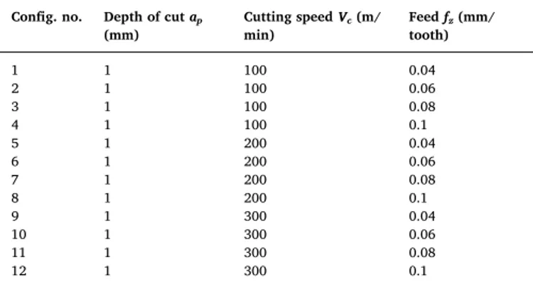
Cutting configurations for the milling experiments. Config. no. Depth of cutap
(mm) Cutting speedVc(m/ min) Feedfz(mm/ tooth) 1 1 100 0.04 2 1 100 0.06 3 1 100 0.08 4 1 100 0.1 5 1 200 0.04 6 1 200 0.06 7 1 200 0.08 8 1 200 0.1 9 1 300 0.04 10 1 300 0.06 11 1 300 0.08 12 1 300 0.1
mechanical properties of each composite component are given in
Table 1 as provided by the supplier. All the NFRP worksurfaces are initially polished with the same grit size and the same polishing pro-cedure to ensure an identical initial state before machining experi-ments.
Milling experiments are performed on DMG-MORIfive axes CNC machine (Ref. CMX U50) that is equipped with a Kistler dynamometer
(Ref. 9255B) to acquire the in-situ cutting forces as shown inFig. 2(a). Theflax fibers orientation is perpendicular to the feed direction. The DCH tool is provided by“Sandvik Coromant – FR” (Ref. 2P460-0952-NA1630) and is illustrated inFig. 2(b). It is composed of six cutting edges. Each edge has two helicalflute orientations. Both have an ab-solute helix angle value of 30°. However, the bottom helicalflute is oriented toward the conventional direction (+ 30°) and the top helical
Fig. 3. SEM images of the machined surface state of UDF/PP composites at different cutting conditions. “HUFE”: High Uncut Fiber Extremities; “LUFE”: Low Uncut Fiber Extremities;“PP”: Polypropylene matrix.
flute is oriented toward the opposite (unconventional) direction (− 30°). The active zone of the milling tool where the cutting has oc-curred is centered in the limit between the two helicalflute orientations as shown inFig. 2(b). Cutting edges of the DCH tool are coated with PVD-TiAlN thin coating thickness (~ 1.5 µm) to avoid microcracks at the tip of the cutting edge when machining without increasing sig-nificantly the cutting edge radius.
Cutting tests are performed by varying the tool kinematics (cutting speed and feed) as summarized inTable 2. Each cutting configuration of Table 2is repeated at least three times to ensure the repeatability. The output values from milling experiments are presented as the mean of these three repeated tests. Errors are considered as the average of the absolute deviations of data repeatability tests from their mean.
For post machining analysis, scanning electron microscope (SEM) (JSM— 5510LV) is used to evaluate the microscopic state of machined surfaces and also to characterize the wear behavior of the milling tool. Moreover, an optical microscope (Nikon SMZ 745T) is used to rate the surface damages at the surface borders.
3. Results and discussion
3.1. Microscopic cutting behavior offlax fibers
Fig. 3 shows typical SEM images that illustrate the microscopic surface state offlax fiber composites after machining. The cutting be-havior offlax fibers is different when changing the cutting conditions. The cutting feed has the most important influence where increasing the feed from 0.04 mm/tooth to 0.1 mm/tooth improves considerably the fibers shearing. This can be observed inFig. 3at all the considered range of cutting speed where the uncutfiber extremities decrease sig-nificantly by increasing the feed. Moreover, the effect of the cutting speed is more obvious at low feed values where increasing the cutting speed deteriorates the flax fibers shearing as shown between
Fig. 3(a)–(c). The rate of uncut fiber extremities is so high at low feed
that the PP matrix is no longer obvious on the SEM images. However, when increasing the feed, the effect of the cutting speed becomes in-significant.
The cutting feed has an important effect on the cutting behavior of flax fibers as it controls the removed chip thickness. Increasing the cutting feed increases the removed chip thickness until reaching the minimum chip thickness required for a good material shearing. On the other side, the fact that the cutting speed affects the cutting behavior at low feed values may be due to a thermal effect that can be induced by increasing the cutting speed as reported also for synthetic fiber
Fig. 5. Specific cutting energy when milling UDF/PP composite with DCH tool.
Fig. 6. Apparent cutting friction coefficient between DCH tool and UDF/PP composite during milling.
composites in[27,28]. Increasing the cutting speed increases the tem-perature at the cutting contact interface, especially when cutting with low feed because the cutting contact lasts longer. This induces a high temperature at the worksurface which makes thefibers and the matrix softer. Therefore,flax fibers lose their stiffness and also the PP matrix support due to the thermal softening of the polymer as reported in[29].
3.2. Tribo-performances of DCH tool on UDF/PP composites
The tribo-functional analysis of DCH tool is performed in this sec-tion using the measured machining forces. The Kystler dynamometer acquires the machining forces in the Cartesian coordinate system (X,Y,Z). The machining forces in the case of milling followed the cy-lindrical coordinate system of the milling tool. Therefore, cutting forces (tangential force in the cylindrical coordinate system) and thrust forces (radial forces in the cylindrical coordinate system) are calculated as described in[30]. Thus, the specific cutting energy and the apparent
cutting friction coefficient can be deduced as shown and described in
[17,19]. The specific cutting (Esc (J/mm3)) energy is calculated
fol-lowing Eq.(1)where P (W) is the cutting power and Q (mm3/min) is
the chip rate. The cutting power can be calculated from the cutting force (Fc(N)) and the cutting speed following Eq.(2), while the chip
rate is deduced from the depth of cut (ap(mm)), the sample thickness (e
(mm)) and the feed speed (Vf(mm/min)) using Eq.(3). The apparent
cutting friction coefficient (µapp) is calculated as the ratio between the
cutting force (Fc(N)) and the thrust force (Fth(N)) following Eq.(4).
= E P Q sc (1) = × P Ft Vc (2) = × × Q ap e Vf (3) = F F µapp c th (4)
Fig. 4 presents both cutting forces and thrust forces during the milling experiments. Thrust forces are higher than cutting forces in the case of DCH tool. Increasing the cutting speed increases both the cutting force and the thrust force for all the cutting configurations. A similar behavior regarding the effect of the cutting speed has been reported for the drilling of naturalfibers composites in[31]. However, the effect of cutting feed is not significantly obvious. Considering the standard de-viation of the measurements, there is a slight decreasing with feed of the cutting force at Vc= 300 m/min (Fig. 4(a)) and a slight increasing
with feed of the thrust force when cutting with Vc= 100 m/min and Vc
= 200 m/min (Fig. 4(b)). The cutting feed is the major parameter that influences the cutting behavior of flax fibers when machining as shown inFig. 3but its effect is not visible on the machining forces ofFig. 4. Therefore, the machining forces do not describe efficiently the cutting behavior of flax fibers in the composite which is different from the cutting behavior of syntheticfiber composites[32].
Using the concept of specific cutting energy, which is the energy
necessary to remove an elementary volume of material,Fig. 5shows that the highest cutting speed (300 m/min) generates the highest en-ergy. The effect of the cutting speed is more visible at low cutting feed. When increasing the feed, the effect of the cutting speed becomes in-significant. Moreover, increasing the cutting feed decreases the energy dissipated by machining, especially at high cutting speed. This en-ergetic analysis corresponds to the cutting behavior offlax fibers shown inFig. 3. The specific cutting energy ofFig. 5reflects thus the shearing
efficiency of flax fibers in the composite where the decrease of the energy values means an efficient fiber shearing during cutting opera-tions. The easiestflax fibers are sheared, the lowest cutting energy is generated.
To better understand the tribo-performances of the DCH tool, the apparent friction coefficient, which is defined locally by the ratio be-tween the cutting force and the thrust force ofFig. 4, is calculated and presented in Fig. 6. The cutting friction behavior between UDF/PP composites and the DCH tool shows an important dependence on the cutting speed. Increasing the cutting speed increases the cutting contact friction. On the other side, increasing the cutting feed decreases slightly the friction coefficient. The friction rising with cutting speed may be due to the thermal generation (explained inSection 3.1) that activates an adhesive friction between the tool face and the polymeric contents of the NFRP composite due to their thermal softening. Increasing the cutting feed decreases this thermal generation by reducing the cutting contact time. These tribo-thermal phenomena occurred at the cutting contact interface could impact the tool wear. The wear issues will be investigated in the last section of this paper.
3.3. Improved machining defects with DCH tool
Machining of naturalfiber composites induces important damages at the surface peripheries that so-called“fluffing defects”[18,19].Fig. 7
shows thefluffing defects in terms of fluffing length at the machined surface borders. Fluffing defect is affected by the tool kinematics. The maximum offluffing length is detected at low cutting speed and low feed (Fig. 7(a)). The cutting speed has the largest effect on fluffing defects where increasing the cutting speed from 100 m/min to 300 m/ min decreases significantly the fluffing length. The effect of the cutting feed is more visible at high cutting speed (fromFig. 7(b) toFig. 7(d)) where increasing the feed also reduces thefluffing defects.
The maximumfluffing length obtained in this study is 541± 56µm which is largely lower than that obtained at similar process parameters but with a conventional milling tool that has one cutting helixflute orientation[18]. These damages concernflax fibers that are near to the borders of the machined surface of the composite because these zones suffer for poor fibers maintaining, especially at the exit of the cutting helixflute since the cutting force is oriented outward the workpiece as shown inFig. 8(a). Indeed, machining with conventional milling tool reduces thefluffing defects at the entry of the cutting flute (the bottom surface border inFig. 8(a)) but increases thefluffing defects at the exit of the cuttingflute (the top surface border inFig. 8(a))[18].
In the case of DCH tool, both top and bottom surface borders have a better maintaining during cutting operation because the double-crossed helixflutes make the cutting edge oriented toward each surface border as shown inFig. 8(b). Therefore, at each surface border, cutting forces are oriented inside the worksurface which provides a strong fiber maintaining on the two sides of the worksurface thanks to the internal composite material.
3.4. Wear analysis of DCH milling tool
To investigate the wear behavior of the DCH milling tool,
accelerated wear test is performed after cutting experiments. A UDF/PP workpiece with the dimensions of (140 × 30 × 4 mm) is used for the wear tests. The accelerated wear test consists of successive cutting passes all over the cutting length of 140 mm with a small cutting depth and a low feed rate. Therefore, a cutting depth of 0.1 mm is considered with a feed rate of 80 mm/min. Since the workpiece width is 30 mm, a clamping width of 10 mm allows a total depth of cut of 20 mm which generates 200 cutting passes. Each wear test takes then 350 min. The three cutting speed values considered in this study (100, 200 and 300 m/min) are explored for the wear analysis.
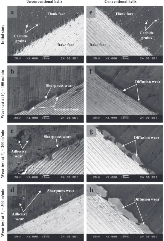
Fig. 9 shows the wear behavior at the flank faces of both the
conventional (CNV) and the unconventional (UCNV) cutting helix flutes. At the initial state, CNV and UCNV flank faces have the same microscopic morphology (Fig. 9(a) andFig. 9(e)). Carbide grains are observed on theflank faces of CNV and UCNV edges because the TiAlN coating is very thin (1.5 µm) and cannot cover the solid carbide mor-phology. Moreover, the cutting edge tip is not round at the initial state. As seen inFig. 9(a) andFig. 9(e), the junction between theflank face and the rake face is not smooth and not continuous since the cutting edges have several micro-cracks of carbide material all over the edge tip. This issue is due to the manufacturing process of the DCH tool in order to make the cutting edges as sharp as possible. After the wear test, carbide grains are reduced from theflank of the UCNV cutting edge (Fig. 9(b)–(d)). However, carbide grains are removed from the flank face of the CNV cutting edge when performing the wear test with a cutting speed of 300 m/min (Fig. 9(h)). This proves that the two cutting edges did not undergo the same tribo-mechanical solicitations.
Microscopic observations ofFig. 9show that the wear behaviors of CNV and UCNV edges are not similar. At the CNV cutting edge, a TiAlN coating removal from theflank face is observed near to the tip of the cutting edge. The TiAlN coating removal increases significantly when increasing the cutting speed from 100 m/min to 300 m/min (Fig. 9(f)→
Fig. 9(g)→Fig. 9(h)). Unlike glass or carbonfibers, no sign of abrasion is detected. This is logic because naturalfibers are not abrasive. The TiAlN coating removal from theflank face may be due to a diffusion wear caused by the induced friction temperature. This thermal effect, which increases by cutting speed increase, leads to atoms release from the TiAlN thin coatingfilm with the high tribo-mechanical cutting so-licitations.
However, UCNV cutting edge does not show the same wear me-chanisms.Fig. 9(b)–(d) indicate that the main wear on the UCNV
cut-ting edge is on the edge tip where this latter becomes smoother and more rounded between theflank face and the rake face which increases the cutting edge radius and, consequently, reduces the cutting edge sharpness. This is what it called“sharpness wear” inFig. 9and this wear type is significantly important in the case of machining NFRP composites[18]. Sharpness wear is not significantly affected by chan-ging the cutting speed. Moreover, adhesive wear is also detected on the UCNV cutting edge and it is more obvious with high cutting speed because of the thermal effect discussed previously.
This investigation demonstrates that the induced temperature due to cutting frictions and high plastic deformation rates especially con-trols the tool wear in the case of NFRP machining. This thermal effect is more important when machining NFRP composites because both nat-ural fibers and polymer matrix are not thermally conductive and, therefore, the induced cutting temperature remains on the cutting in-terface.
4. Conclusions
This paper investigates improved milling tool geometry for ma-chining naturalfiber reinforced plastic (NFRP) composites. This milling tool is characterized by a double-crossed helix (DCH) and is tested with unidirectional flax fibers reinforced polypropylene (UDF/PP) compo-sites. Both cutting performances and tool wear are explored in this study. The following conclusions can be drawn:
•
From the microscopic observations, the cutting feed has the most significant impact on the flax fibers shearing where increasing the feed improves the shearing efficiency. However, increasing the cutting speed reduces the shearing efficiency of flax fibers. The same observations are retained from the energetic analysis where in-creasing the feed from 0.04 mm/tooth to 0.1 mm/tooth decreases the specific cutting energy by 67% for a cutting speed of 300 m/min, 51% for a cutting speed of 200 m/min and 60% for a cutting speed of 100 m/min.•
The cutting speed influences the cutting friction. Increasing thecutting speed from 100 m/min to 300 m/min increases the apparent friction coefficient by 60% for a feed of 0.04 mm/tooth, 120% for a feed of 0.06 mm/tooth, 100% for a feed of 0.08 mm/tooth and 87% for a feed of 0.1 mm/tooth.
•
Cutting with DCH milling tool improves considerably the surface finish in terms of fluffing defects at the surface borders comparing with standard milling tools.•
Although the increase in cutting speed has a negative effect on the flax fibers shearing, increasing the cutting speed reduces the fluffing defects on the machined surface borders by 30–40% for low feed (0.04 mm/tooth) and 60–70% for high feed (0.1 mm/tooth) which improves the surfacefinish.•
For milling NFRP composites with DCH tool, the wear mechanisms are not the same on the conventional and the unconventional cut-ting edges. Diffusion wear is the main wear mechanism in the conventional edge while sharpness wear remains the important wear mechanism in the unconventional cutting edge. Further tribo-mechanical investigations will be performed by the authors to un-derstand more the origin of wear difference between the two helix orientations.Acknowledgement
This study has been performed with the own laboratory's funds and has not received any external funding source.
References
[1] A. Shalwan, B.F. Yousif, In state of art: mechanical and tribological behaviour of polymeric composites based on naturalfibres, Mater. Des. 48 (2013) 14–24,
https://doi.org/10.1016/j.matdes.2012.07.014.
[2] D.U. Shah, Developing plantfibre composites for structural applications by opti-mising composite parameters: a critical review, J. Mater. Sci. 48 (2013) 6083–6107,
https://doi.org/10.1007/s10853-013-7458-7.
[3] H.L. Bos, J. Müssig, M.J.A. van den Oever, Mechanical properties of short-flax-fibre reinforced compounds, Compos. Part A Appl. Sci. Manuf. 37 (2006) 1591–1604,
https://doi.org/10.1016/J.COMPOSITESA.2005.10.011.
[4] S. Goutianos, T. Peijs, B. Nystrom, M. Skrifvars, Development offlax fibre based textile reinforcements for composite applications, Appl. Compos. Mater. 13 (2006) 199–215,https://doi.org/10.1007/s10443-006-9010-2.
[5] L. Jiang, D. Walczyk, G. McIntyre, R. Bucinell, G. Tudryn, Manufacturing of bio-composite sandwich structures using mycelium-bound cores and preforms, J. Manuf. Process. 28 (2017) 50–59,https://doi.org/10.1016/J.JMAPRO.2017.04. 029.
[6] M. Ramesh, K. Palanikumar, K. Hemachandra Reddy, Plantfibre based bio-com-posites: sustainable and renewable green materials, Renew. Sustain. Energy Rev. 79 (2017) 558–584,https://doi.org/10.1016/J.RSER.2017.05.094.
[7] L. Yan, N. Chouw, K. Jayaraman, Flaxfibre and its composites – a review, Compos. Part B Eng. 56 (2014) 296–317,https://doi.org/10.1016/J.COMPOSITESB.2013. 08.014.
[8] M.R. Sanjay, G.R. Arpitha, L.L. Naik, K. Gopalakrishna, B. Yogesha, Applications of naturalfibers and its composites: an overview, Nat. Resour. 07 (2016) 108–114,
https://doi.org/10.4236/nr.2016.73011.
[9] J.K. Pandey, S.H. Ahn, C.S. Lee, A.K. Mohanty, M. Misra, Recent advances in the application of naturalfiber based composites, Macromol. Mater. Eng. 295 (2010) 975–989,https://doi.org/10.1002/mame.201000095.
[10] J. Holbery, D. Houston, Natural-fiber-reinforced polymer composites in automotive applications, JOM 58 (2006) 80–86,https://doi.org/10.1007/s11837-006-0234-2. [11] S.N. Monteiro, F.P.D. Lopes, A.S. Ferreira, D.C.O. Nascimento, Natural-fiber
polymer-matrix composites: cheaper, tougher, and environmentally friendly, JOM 61 (2009) 17–22,https://doi.org/10.1007/s11837-009-0004-z.
[12] M. Khalfallah, B. Abbès, F. Abbès, Y.Q. Guo, V. Marcel, A. Duval, F. Vanfleteren, F. Rousseau, Innovativeflax tapes reinforced Acrodur biocomposites: a new alter-native for automotive applications, Mater. Des. 64 (2014) 116–126,https://doi. org/10.1016/j.matdes.2014.07.029.
[13] M. Ho, H. Wang, J.-H. Lee, C. Ho, K. Lau, J. Leng, D. Hui, Critical factors on manufacturing processes of naturalfibre composites, Compos. Part B Eng. 43 (2012) 3549–3562,https://doi.org/10.1016/J.COMPOSITESB.2011.10.001. [14] C. Baley, Analysis of theflax fibres tensile behaviour and analysis of the tensile
stiffness increase, Compos. - Part A Appl. Sci. Manuf. 33 (2002) 939–948,https:// doi.org/10.1016/S1359-835X(02)00040-4.
[15] F. Chegdani, M. El Mansori, S. Mezghani, A. Montagne, Scale effect on tribo-me-chanical behavior of vegetalfibers in reinforced bio-composite materials, Compos. Sci. Technol. 150 (2017) 87–94,https://doi.org/10.1016/j.compscitech.2017.07. 012.
[16] F. Chegdani, Z. Wang, M. El Mansori, S.T.S. Bukkapatnam, Multiscale tribo-me-chanical analysis of naturalfiber composites for manufacturing applications, Tribol.
Int. 122 (2018) 143–150,https://doi.org/10.1016/j.triboint.2018.02.030. [17] F. Chegdani, S. Mezghani, M. El Mansori, A. Mkaddem, Fiber type effect on
tribo-logical behavior when cutting naturalfiber reinforced plastics, Wear 332–333 (2015) 772–779,https://doi.org/10.1016/j.wear.2014.12.039.
[18] F. Chegdani, S. Mezghani, M. El Mansori, Experimental study of coated tools effects in dry cutting of naturalfiber reinforced plastics, Surf. Coat. Technol. 284 (2015) 264–272,https://doi.org/10.1016/j.surfcoat.2015.06.083.
[19] F. Chegdani, S. Mezghani, M. El Mansori, On the multiscale tribological signatures of the tool helix angle in profile milling of woven flax fiber composites, Tribol. Int. 100 (2016) 132–140,https://doi.org/10.1016/j.triboint.2015.12.014.
[20] A. Ben Soussia, A. Mkaddem, M. El Mansori, Rigorous treatment of dry cutting of FRP– interface consumption concept: a review, Int. J. Mech. Sci. 83 (2014) 1–29,
https://doi.org/10.1016/J.IJMECSCI.2014.03.017.
[21] J. Xu, M. El Mansori, Wear characteristics of polycrystalline diamond tools in or-thogonal cutting of CFRP/Ti stacks, Wear 376–377 (2017) 91–106,https://doi.org/ 10.1016/J.WEAR.2016.11.038.
[22] C. Kuo, C. Wang, S. Ko, Wear behaviour of CVD diamond-coated tools in the drilling of woven CFRP composites, Wear 398–399 (2018) 1–12,https://doi.org/10.1016/ J.WEAR.2017.11.015.
[23] A. Mkaddem, A. Ben Soussia, M. El Mansori, Wear resistance of CVD and PVD multilayer coatings when dry cuttingfiber reinforced polymers (FRP), Wear 302 (2013) 946–954,https://doi.org/10.1016/J.WEAR.2013.03.017.
[24] J. Sheikh-Ahmad, J.P. Davim, Tool wear in machining processes for composites, in: H. Hocheng (Ed.), Mach. Technol. Compos. Mater. Woodhead Publishing, Cambridge, 2012, pp. 116–153, ,https://doi.org/10.1533/9780857095145.1.116.
[25] U. Nirmal, K.O. Low, J. Hashim, On the effect of abrasiveness to process equipment using betelnut and glassfibres reinforced polyester composites, Wear 290–291 (2012) 32–40,https://doi.org/10.1016/j.wear.2012.05.022.
[26] B.F. Yousif, U. Nirmal, Wear and frictional performance of polymeric composites aged in various solutions, Wear 272 (2011) 97–104,https://doi.org/10.1016/j. wear.2011.07.006.
[27] R. Vinayagamoorthy, A review on the machining offiber-reinforced polymeric la-minates, J. Reinf. Plast. Compos. 37 (2018) 49–59,https://doi.org/10.1177/ 0731684417731530.
[28] A. Uysal, Effects of cutting parameters on drilling performance of carbon black–-reinforced polymer composite, Proc. Inst. Mech. Eng. Part B J. Eng. Manuf. 232 (2018) 1133–1142,https://doi.org/10.1177/0954405416662084.
[29] F. Chegdani, B. Takabi, B.L. Tai, M. El Mansori, S.T.S. Bukkapatnam, Thermal ef-fects on tribological behavior in machining naturalfiber composites, Procedia Manuf. 26 (2018) 305–316,https://doi.org/10.1016/J.PROMFG.2018.07.039. [30] D. Kalla, J. Sheikh-Ahmad, J. Twomey, Prediction of cutting forces in helical end
millingfiber reinforced polymers, Int. J. Mach. Tools Manuf. 50 (2010) 882–891,
https://doi.org/10.1016/j.ijmachtools.2010.06.005.
[31] R. Vinayagamoorthy, I.V. Manoj, G. Narendra Kumar, I. Sai Chand, G.V. Sai Charan Kumar, K. Suneel Kumar, A central composite design based fuzzy logic for optimization of drilling parameters on naturalfiber reinforced composite, J. Mech. Sci. Technol. 32 (2018) 2011–2020,https://doi.org/10.1007/s12206-018-0409-0. [32] H. Wang, J. Sun, J. Li, L. Lu, N. Li, Evaluation of cutting force and cutting
tem-perature in milling carbonfiber-reinforced polymer composites, Int. J. Adv. Manuf. Technol. 82 (2016) 1517–1525,https://doi.org/10.1007/s00170-015-7479-2.