Science Arts & Métiers (SAM)
is an open access repository that collects the work of Arts et Métiers Institute of Technology researchers and makes it freely available over the web where possible.
This is an author-deposited version published in: https://sam.ensam.eu Handle ID: .http://hdl.handle.net/10985/6750
To cite this version :
Paul SANDULESCU, Xavier KESTELYN, Eric SEMAIL, Antoine BRUYERE, Boris BOUCHEZ, Luis DE SOUSA - A Multiphase Traction/Fast-Battery-Charger Drive for Electric or Plug-in Hybrid Vehicles In: IEEE Vehicle Power and Propulsion Conference (VPPC), France, 20100901 -IEEE Vehicle Power and Propulsion Conference (VPPC) - 2010
Any correspondence concerning this service should be sent to the repository Administrator : archiveouverte@ensam.eu
A Multiphase Traction/Fast-Battery-Charger Drive
for Electric or Plug-in Hybrid Vehicles
Solutions for Control in Traction Mode
A. Bruyère, L. De Sousa, B. BouchezValeo Engine and Electrical Systems VEES 14, avenue des Béguines,
95800 Cergy Saint-Christophe, France antoine.bruyere@valeo.com
P. Sandulescu1,2, X. Kestelyn1,2, E. Semail1,2 (1)Arts et Metiers PARISTECH, L2EP, Lille, France
(2)Univ Lille Nord de France, L2EP, Lille, France 8 Bd Louis XIV, 59046 LILLE, France
eric.semail@ensam.eu Abstract— For Electric Vehicles (EV), the charger is one of the
main technical and economical weaknesses. This paper focuses on an original electric drive [1]-[3] dedicated to the vehicle traction and configurable as a battery charger without need of additional components. This cheap solution can outfit either electric or plug-in hybrid automotive vehicles, without needing additional mass and volume dedicated to the charger. Moreover, it allows a high charging power, for short duration charge cycles. However, this solution needs specific cares concerning the electrical machine control. This paper deals with the control of this drive [1], focusing on traction mode. In introduction, a review is done about topologies of combined on-board chargers. Then, the studied topology is introduced; using a 3-phase brushless machine supplied with a 6-leg Voltage Source Inverter (VSI). A model for its control is defined in the generalized Concordia frame, considering the traction mode. Then, an analysis of this model is established using a multimachine theory and a graphical formalism (the Energetic Macroscopic Representation denoted EMR). Using EMR, a description of energy flows shows specific control constraints. Indeed, numerical simulations illustrate the perturbations on the currents and the torque when controlling the machine with standard control methodologies. An improved control, deduced from the previous analysis, shows good performances, strongly reducing currents and torque ripples.
Keywords- Electric Vehicle, Plug-in Hybrid Vehicle, On-board Battery Charger, H-bridge Voltage Source Inverter, Multiphase Drive, Control
I. INTRODUCTION
For both electric and Plug-in hybrid vehicles [4], one of the main technical and economical weaknesses concerns the use of a charger. Indeed, technically, an on-board charger means loading extra volume and extra mass. Otherwise, an off-board charger does not allow recharging the battery anywhere. In both cases, economically, using a charger means extra cost due to a specific converter. In the last few years, several solutions have been tested, combining the motor converter with the motor windings to make on-board chargers [5]-[9]. This is possible since both charger and motor with its supply device are composed of windings, capacitors and power electronics. Moreover, the battery recharge only occurs when the car is stopped, so, the drive is not used for the two different operation modes at the same time. In [5], several of
these solutions are described and are called “combination topologies”. Nevertheless, theses solutions are only suitable for a single-phase charge and cannot offer a faster charging option by a three-phase grid connection. Other solutions have been proposed in [6]-[7], but two main drawbacks are recurrent. The first one is the need of a high current relay to connect the AC grid on the electrical machine’s coils. This is still an over-cost that makes the solution less attractive. The second one is the generation of a rotating magnetic air-gap field, which is able to induce high voltage on the rotor’s windings or to move the rotor. This is a serious issue in case of Permanent-Magnet Synchronous Machine (PMSM). In this paper, an original combination topology battery charger is studied [1]-[3]. This solution ensures lack of air-gap field due to the stator windings when these windings are supplied in charge mode. Moreover, it allows both single-phase and three-phase (fast) charging modes. However, this topology induces specific cares for control, due to the need of controlling three independent currents.
In a first part, this original topology is introduced. Note that more details about the topology, its assets and drawbacks, can be found in [1].
A model is then established, considering the drive control in traction mode. Two specific tools are used to analyze the model: first, the multimachine theory [10]-[12]. This tool has been developed specifically for studying multiphase drives. Then, a graphical formalism called Energetic Macroscopic Representation (EMR) [14]-[17]. EMR allows a representation of models fitted with an energy study, in view of controlling energy flows. Using both the multimachine theory and EMR, specific constrains appear for controlling the machine.
In a third section, two kinds of control in traction mode are tested through numerical simulations. These simulations show that standard control methodologies, fitted with standard 3-phase drive control, can induce strong perturbation on currents and torque. Thus, an improved control is tested, showing a strong reduction of these perturbations. The influence of the Pulse Width Modulation (PWM) technique is also studied.
II. DRIVE DESCRIPTION
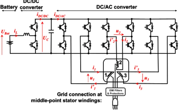
The drive is composed of a three-phase machine whose phases are not electrically coupled (no wye, no delta-coupling). Each phase is supplied by a full H-bridge Voltage Source Inverter (VSI). In comparison with classical three-phase wye coupled machines supplied by a three-leg VSI, this topology allows:
• Imposing a higher voltage to each phase;
• Using each one of the three phases of the machine as an inductance for achieving a battery charger.
Of course, if it is possible with the classical topology to use only two power components and two drivers to achieve each one leg of the three legs, then the proposed topology suffers apparently of twice more power components and more complex control than the classical topology. Nevertheless, it must be remarked that the maximum current in each device will be half less, which allows the use of smaller and cheaper components [18].
In Figure 1. the VSI energy source is the DC/DC converter capacitor, imposing the voltage UC. This converter works as a
voltage boost in traction mode. In the next discussion, UC is
assumed to be constant and the study focuses on the machine control using the VSI.
i2
DC/DC converter Battery
Grid connection at middle-point stator windings:
DC/AC converter UC u1 u3 u2 i1 i3 UBat iL iDC/AC iDC/DC EMI Filters & Protections i’1 i’3 i’2 1 3 2 i2 DC/DC converter Battery Grid connection at middle-point stator windings:
DC/AC converter UC u1 u3 u2 i1 i3 UBat iL iDC/AC iDC/DC EMI Filters & Protections i’1 i’3 i’2 1 3 2
Figure 1. Drive Topology
III. MODELLING FOR CONTROL IN TRACTION MODE
The studied Permanent Magnet Synchronous Machine (PMSM) is supposed to be a non-saturated smooth pole (without reluctance effect) machine. Then it verifies equation (1) that can be rewritten with a vectorial formalism by equation (2). ⎥ ⎥ ⎥ ⎦ ⎤ ⎢ ⎢ ⎢ ⎣ ⎡ + ⎟ ⎟ ⎟ ⎠ ⎞ ⎜ ⎜ ⎜ ⎝ ⎛ ⎥ ⎥ ⎥ ⎦ ⎤ ⎢ ⎢ ⎢ ⎣ ⎡ ⎥ ⎥ ⎥ ⎦ ⎤ ⎢ ⎢ ⎢ ⎣ ⎡ + ⎥ ⎥ ⎥ ⎦ ⎤ ⎢ ⎢ ⎢ ⎣ ⎡ = ⎥ ⎥ ⎥ ⎦ ⎤ ⎢ ⎢ ⎢ ⎣ ⎡ 3 2 1 3 2 1 3 2 1 S 3 2 1 L M M M L M M M L R e e e i i i dt d i i i u u u (1)
[ ]
(
S S)
S S S S R dt L i e d i uG = G + G +G (2)A. Introduction to the multimachine theory
By projecting (2) into the two orthonormal subspaces M0 and M1, associated with the two eigenvalues LM0 and LM1 of
the inductance matrix [LS], it can be found equation (3) and
(4) [10]-[12]. The mathematic transformation used to operate the projection from (1) to (3) (or from (2) to (4)) is the full Concordia transformation characterized by matrix C3.
⎥ ⎥ ⎥ ⎦ ⎤ ⎢ ⎢ ⎢ ⎣ ⎡ + ⎟⎟ ⎟ ⎟ ⎠ ⎞ ⎜⎜ ⎜ ⎜ ⎝ ⎛ ⎥ ⎥ ⎥ ⎦ ⎤ ⎢ ⎢ ⎢ ⎣ ⎡ ⎥ ⎥ ⎥ ⎦ ⎤ ⎢ ⎢ ⎢ ⎣ ⎡ + ⎥ ⎥ ⎥ ⎦ ⎤ ⎢ ⎢ ⎢ ⎣ ⎡ = ⎥ ⎥ ⎥ ⎦ ⎤ ⎢ ⎢ ⎢ ⎣ ⎡ ⎥ ⎥ ⎥ ⎦ ⎤ ⎢ ⎢ ⎢ ⎣ ⎡ − − − = ⎥ ⎥ ⎥ ⎦ ⎤ ⎢ ⎢ ⎢ ⎣ ⎡ = ⎥ ⎥ ⎥ ⎦ ⎤ ⎢ ⎢ ⎢ ⎣ ⎡ β M α M M M M M M M M M M M e e e i i i dt d i i i u u u u u u u u u 1 1 0 1 1 0 M1 M1 M0 1 1 0 S 3 2 1 3 2 1 1 1 0 L 0 0 0 L 0 0 0 L R 2 / 3 2 / 3 0 2 / 1 2 / 1 2 1 1 1 3 1 ] 3 C [ β α β α β α (3)
(
)
⎪ ⎪ ⎩ ⎪ ⎪ ⎨ ⎧ + ⎟ ⎟ ⎠ ⎞ ⎜ ⎜ ⎝ ⎛ ⎥ ⎦ ⎤ ⎢ ⎣ ⎡ + = + + = 1 1 M1 M1 1 S 1 0 0 M0 0 S 0 L 0 0 L R L R M M M M M M M M e i dt d i u e i dt d i u G G G G (4)As the two subspaces defined with the generalized Concordia transformation are orthogonal, two power flows can be emphasized uS.iS uM1.iM1 uM0.iM0 G G G G G G + = , leading to the
introduction of two fictitious machines also denoted M0 and M1 [10]-[12]. M0 is called the “zero-sequence fictitious machine” and M1 is the “main fictitious machine” (because M1 is at the origin of the “main” part of energy conversion). Then, the torque of the real machine T is the sum of the two fictitious machine torques TM0 and TM1 (5). At last, both
fictitious machines rotation speed is Ω (5). However, each one is characterized by its own family of harmonics as described in Table I. This means, as example, that M1 will be only affected by the voltage (or currents, or emf) harmonics ranks 1, 2, 4, 5, 7… It can be remarked, for a wye-coupled machine, that the 3rd harmonic current (and ranks multiple of 3) are
structurally null (if bearing currents are neglected). This means that iM0 is always equal to zero. Consequently, a
simplification is generally made for the standard 3-phase-machine/3-leg-VSI drives, which consists in neglecting M0. Then, only M1 is used to control the machine. To be noted that the definition of M1 is equivalent with the notion of a “dq-machine” in “standard” Park frame. With the considered topology (Figure 1. ) the current iM0 will have to be controlled
by an adequate Voltage Source Modulation because the Park transformation defined for standard drives is not fitted.
⎩ ⎨ ⎧ Ω = Ω = Ω + = 1 0 1 0 M M M M T T T (5)
TABLE I. HARMONICS REPARTITION THROUGH THE FICTITIOUS MACHINE SUBSPACES DEFINED WITH THE CONCORDIA TRANSFORMATION Fictitious Machines Harmonics Family Description
M0 0, 3, 6, 9, 12…
B. Model Representation using Energetic Macroscopic Representation (EMR)
All along the multimachine theory development, another tool has been associated with in order to help its using [10]-[11]. This tool is a graphical formalism focused on energy flows representation, called Energetic Macroscopic Representation (EMR) [14]-[17]. It is also used to define systematic rules for organizing the control structure and control strategies. This is all the more interesting that the system is characterized with many energy couplings (energy nodes). EMR has been developed at L2EP (Laboratory of Electrical Engineering and Power Electronics, Lille, France). In appendix, the main EMR elements meaning is reminded in order to help understanding the next figures.
In order to help control of power transfers in electromechanical applications, EMR is based on the action/reaction principle: each action induces its associated reaction and the product of both is the instantaneous power. With EMR, each action and reaction are represented with superposed arrows; this gives a direct view of energy flows. Then, each energy sub-systems of the drive are connected together using the action/reaction principle. Moreover, the integral causality is always respected in order to fit with the physical reality. For example, in Figure 2. it is shown how connecting each others the energy sub-systems of the studied drive, using the action/reaction principle. Thus, Figure 2. means: the DC/DC converter is considered as the electrical energy source for the drive. It imposes the voltage UC as
“action” to the drive. Then, the DC/DC converter is connected to the VSI, which imposes the associated reaction: the DC bus current iDC/AC. The VSI tuning input is mDC/AC
K
, representing the modulation functions. Next, the VSI also imposes the 3-dimensional voltage vector uGS to the machine stator windings. The associated reaction to uGS is the current vector
S
i
G
, imposed by an accumulation of energy block (representing the magnetic energy accumulation in windings). From this energy accumulation block point of view, the emf vector eGS is seen as a perturbation input. At last, the torque T is an output of the electromechanical conversion block. It is a function of the two inputs of this block: iGS and the rotation speed Ω (rotation speed is supposed to be imposed by system outside). Finally let us check that this scheme is a description of the energetic chain. Indeed, each couple of superposed arrows represents the power when multiplying each action with its associated reaction. Chassis T Ω iS iS uS eS mDC/AC UC iDC/AC Electrical Machine DC/DC DC/AC converter Chassis T Ω iS iS iS iS uS uS eS eS mDC/AC mDC/AC UC iDC/AC Electrical Machine DC/DC DC/DC DC/AC converter
Figure 2. Machine and Converter EMR Representation in the Natural Reference Frame
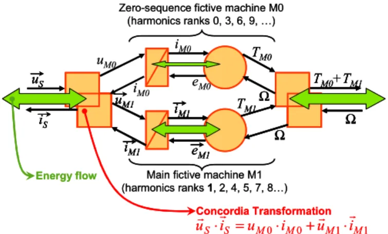
The representation of Figure 2. is given in the natural UVW frame, what refers to the expressions (1) and (2). Now, considering the expressions (3)-(5), defined using the multimachine theory, a new representation can be introduced for the electrical machine (Figure 3. ). In Figure 3. the Concordia transformation is represented with an electrical coupling. This illustrates the energy distribution between the two fictitious machines M0 and M1, stacked one above the other one (energy flows are represented with green double arrows in the figure. It is assumed that the main part of energy passes through the main fictitious machine M1). To be noted that the energy distribution operated with the Concordia transformation also naturally respects the harmonics distribution depicted with TABLE I. Concretely, this means, taking the example of the voltage vector uGS , potentially containing an infinity of harmonics, that M1 is only supplied with voltage harmonics of ranks 1, 2, 4, 5, 7, … Concerning the zero-sequence M0 machine, it is supplied with voltage harmonics of ranks 3, 6, 9, … There is no interaction between these harmonics families and both fictitious machine creates its own torque. The total torque T is the sum of TM0 and TM1.
These notions were introduced with (4) and (5). Here it is graphically expressed in terms of energy distribution into independent “fictitious machines”. Finally, this approach will help design and control analysis.
iM0 eM0 iM0 uM0 iM1 uM1 uS iS iM1 eM1 TM0+TM1 Ω TM0 Ω TM1 Ω
Zero-sequence fictive machine M0 (harmonics ranks 0, 3, 6, 9, …)
Concordia Transformation
Main fictive machine M1 (harmonics ranks 1, 2, 4, 5, 7, 8…) 1 1 0 0 M M M M S S i u i u i uG ⋅G = ⋅ +G ⋅G Energy flow iM0 eM0 iM0 uM0 iM1 uM1 iM1 iM1 uM1 uM1 uS iS uS uS iS iS iM1 eM1 iM1 iM1 eM1 eM1 TM0+TM1 Ω TM0+TM1 Ω TM0 Ω TM0 Ω TM1 Ω TM1 Ω
Zero-sequence fictive machine M0 (harmonics ranks 0, 3, 6, 9, …)
Concordia Transformation
Main fictive machine M1 (harmonics ranks 1, 2, 4, 5, 7, 8…) 1 1 0 0 M M M M S S i u i u i uG ⋅G = ⋅ +G ⋅G Energy flow
Figure 3. Electrical Machine Representation in the Concordia Reference Frame
To conclude with this chapter, Figure 4. shows the manner with which the control structure is organized using EMR. The formalism helps defining a control structure by an inversion of the energy chain. For conversion blocks, the inversion can be directly established. For energy accumulation blocks, the inversion needs a controller and the associated measurements. Here, controllers are used to control the fictitious machines currents. The representation of Figure 4. fits with the control of the torque T: torque reference is split into two components
TM0 ref and TM1 ref. Then, these references are transformed in
currents references, inversing the model electromechanical conversion blocks. The currents are controlled using controllers, leading to the voltage references. At last, the inverse Concordia transformation leads to the voltage
reference expressed in the natural UVW frame. To be noted that M1 currents can be controlled in a rotating Park frame, exactly as it is generally done for standard 3-phase drives.
iM0 eM0 iM0 uM0 iM1 uM1 uS iS iM1 eM1 TM0+TM1 Ω TM0 Ω TM1 Ω uS ref uM0 ref uM1 ref i M1 ref iM0 ref Tref TM0 ref TM1 ref M0 control M1 control Concordia inverse M0 and M1 currents controllers Direct inversion Torque reference repartition iM0 eM0 iM0 uM0 iM1 uM1 uS iS iM1 eM1 TM0+TM1 Ω TM0 Ω TM1 Ω uS ref uM0 ref uM1 ref i M1 ref iM0 ref Tref TM0 ref TM1 ref M0 control M1 control iM0 eM0 iM0 uM0 iM1 uM1 iM1 iM1 uM1 uM1 uS iS uS uS iS iS iM1 eM1 iM1 iM1 eM1 eM1 TM0+TM1 Ω TM0+TM1 Ω TM0 Ω TM0 Ω TM1 Ω TM1 Ω uS ref uS ref uM0 ref uM1 ref uM1 ref i M1 ref iM1 ref iM0 ref Tref TM0 ref TM1 ref M0 control M1 control Concordia inverse M0 and M1 currents controllers Direct inversion Torque reference repartition Figure 4. 3-Phase Machine Control Structure Taking Into Account the Two Fictitious Machines
IV. CONTROL AND DESIGN CONSTRAINTS POINTING OUT
The multimachine theory, associated with EMR, has been developed and experimentally validated for 5-, 7- and 9- phase drives [10]-[13]. Now, it is used to illustrate the specific control constraints of the topology described with Figure 1.
A. Tests Conditions
In order to illustrate the influence of the zero-sequence fictitious machine M0 control, it is considered a machine with non-sinus electromotive forces (emf), characterized with 15% of emf 3rd harmonic.
Then, for each test, the following operating mode is set: - The rotation speed is fixed: N = 1000 rpm.
- M1 currents are controlled in a dq-Park rotating frame with Proportional + Integral (PI) controllers (as it is usually done for standard 3-phase drives). The following references are arbitrarily chosen: iM1d-ref = 10 A,
iM1q-ref = -30 A.
- Initial conditions of currents: 0 A.
- M1 currents closed loop time constant tuning: 2.1 ms. - The simulations are carried in continuous mode (without
discrete sampling effects).
Taking this operation mode as reference, the studies will focus on controlling M0. Step after step, we will answer the following questions:
- What is the influence of the emf waveform? - What is the influence of the voltage modulation?
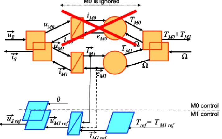
B. Standard Control
A first control is carried out. This control uses a standard control methodology (developed for standard 3-phase-machine/3-leg-VSI drives). Thus, the zero-sequence fictitious machine M0 is not taken into account and the control structure is designed only considering M1 (Figure 5. ). Then, the control is established in a standard way, controlling the dq-currents in
the rotating Park frame associated with M1, as described in the tests conditions.
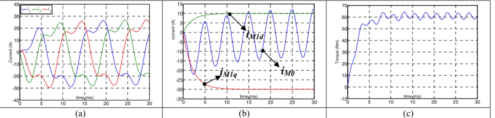
The results of this first control are shown in Figure 9. (a): The currents in the natural UVW frame, (b): the currents in Park frame, (c): the torque. Because emf contains a 3rd
harmonic and because M0 is not controlled, the current also naturally contains a 3rd harmonic. The main drawbacks
concern extra losses and torque ripples. This illustrates why a standard control is not fitted with the considered topology.
iM0 eM0 iM0 uM0 iM1 uM1 uS iS iM1 eM1 TM0+TM1 Ω TM0 Ω TM1 Ω uS ref 0 uM1 ref iM1 ref Tref= TM1 ref M0 control M1 control M0 is ignored iM0 eM0 iM0 uM0 iM1 uM1 iM1 iM1 uM1 uM1 uS iS uS uS iS iS iM1 eM1 iM1 iM1 eM1 eM1 TM0+TM1 Ω TM0+TM1 Ω TM0 Ω TM0 Ω TM1 Ω TM1 Ω uS ref uS ref 0 uM1 ref uM1 ref iM1 ref iM1 ref Tref= TM1 ref M0 control M1 control M0 is ignored
Figure 5. 3-Phase Machine Control Structure in Usual Case
C. Controlling the zero-sequence current
M0 being at the origin of pulsating torque when iM0 is not
controlled, we will now use the control structure described in Figure 4. A focus is brought to M0 current control in Figure 6. In this second test, it is considered an ideal control of iM0, with
a perfect compensation of the perturbation eM0 (Figure 6. ) To
cancel the M0 pulsating torque, it is chosen as reference for
iM0: iM0 ref = 0 A. In Figure 10. (b), iM0 perfectly follows its
reference. Then, iM1 currents are always controlled as
previously. The global behavior is identical to an electrically coupled machine and the torque is smooth (Figure 10. (c)). So it is demonstrated that controlling iM0 is a solution to
compensate the lack of electrical coupling.
s M0 M0 1 K τ + + - iM0 eM0 + - iM0-ref + + uM0 C(s) iM0-ref uM0 iM0 iM0 eM0 uM0-ref iM0-ref uM0 iM0 iM0 eM0 uM0-ref s M0 M0 1 K τ + + -+ - iM0 eM0 + -+ - iM0-ref + ++ + uM0 C(s) iM0-ref uM0 iM0 iM0 eM0 uM0-ref iM0-ref uM0 iM0 iM0 eM0 uM0-ref
Figure 6. Focus on M0 Fictitious Machine Control
D. Influence of the Pulse Width Modulation (PWM)
Until this point, the VSI was modeled as amplifier that imposes average voltages. Now the influence of the Pulse Width Modulation (PWM) is studied. Indeed, it is generally assumed that PWM is at the origin of common mode voltage (6) which affects the zero-sequence M0 fictitious machine. In the standard case, with an electrical coupling, this common
mode voltage can be ignored (except for EMC considerations or bearing current calculation). In the considered system, the common mode voltage, defined by (6), is at the origin of a zero-sequence current iM0. This current can strongly affect the
currents of the machine and its torque.
(
u1 u2 u3)
/3ucommonmode= + + (6)
In order to precise this point, two kinds of common mode voltages are compared: in Figure 11. a standard two-level PWM is used instead of a three-level in Figure 12. Currents of the machine are clearly less noisy in Figure 12. The origin of this difference appears by looking at zero-sequence current in Figure 11. (c) and Figure 12. (c).
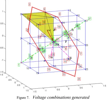
We propose a further analysis of the influence of PWM by using a space vector modeling of the VSI. To begin with, the 3-phase-machine/3-leg-VSI case is taken into account. In this case, the number of voltage combinations that can be selected is equal to 23=8. Now, with the studied topology (Figure 1. )
the applied voltage pulses range belongs to {-E, 0, +E}. and the number of possible vectors to be selected is 33=27. In what
follows, it will be considered that each phase of the machine is associated with its own dimension in the 3-dimensions Cartesian space. So, the abc-basis is defined. Now, the 27 voltage combinations that can be applied by the VSI to the electrical phases of the machine are plotted in Figure 7. (intersections of blue lines).
Figure 7. Voltage combinations generated by the three-level VSI
In order to understand how the common-mode voltage is generated, the voltage vectors produced by the inverter in the natural abc-basis will be analyzed from a different perspective. To do so, the Concordia transformation will be applied, projecting the abc-basis vectors to the fictitious machines M0 and M1 frames. Thus, a new three-dimensional 0αβ-base is defined. In Figure 7. the standard αβ plane (M1 subspace) of a
three-phase machine is represented by the standard hexagon
composed of vectors . In the case
analyzed in this paper, the supplementary zero-sequence M0-subspace has also to be taken into account (green dashed-line). It is noticed that M0 subspace is a one-dimensional subspace (zero-sequence straight line) orthogonal to the M1 two-dimensional M1-subspace (αβ plane). This transformation is in accordance with the electrical machine representation in Figure 3. for which the zero-sequence fictitious machine (M0) is decoupled from the main fictitious machine (M1).
In Figure 7. the projections over the decoupled bases of all the vectors that can be generated using a three-level VSI have been plotted (numbers represented into squares ). The VSI voltage vectors projection in the 0αβ-base affects either M0, or M1, or both M0 and M1 subspaces. Consequently, in order to minimize the zero-sequence current, control strategies can be carried out, using VSI voltage vectors which projections on M0 straight-line subspace is weak (verily null).
Now, a classical PWM control using a three-leg VSI (Figure 11. ) is compared with the 3-levels PWM control carried out with the three H-bridge VSI (Figure 12. ). The 8 vectors generated by the three-leg VSI can be represented with the 8 corners (3 9 27 21 1 7 25 19) of the cube in Figure 7. These vectors amount of zero-sequence component belongs to {(1/ 3), ( 3)}. A classical symmetrical PWM modulation [19] will use 4 vectors per PWM period. Two of these vectors amount is the largest zero-sequence component, while the rest of them amount is never null (1/ 3). So it is expected that the zero-sequence fictitious machine M0 will be highly stimulated by these vectors, thus M0 current will be important.
Figure 8. Voltage vectors amount of zero-sequence component;
red-vectors: two-level PWM, green-vectors: three-level PWM
Using the inverter topology presented in Figure 1. and taking advantage of the 27 voltage vectors, it is possible to use only voltages whose amount of zero-sequence component belongs to {(0), (+/−1/ 3)} (blue circles in Figure 8. ) By applying a three-level symmetrical PWM, it can be proven that only these voltages vectors, near of the αβ plane, are used. Thus, a control using these vectors will drastically reduce the M0 current, at the origin of the torque ripples and the additional power losses. This it what is shown in Figure 12. in comparison with Figure 11.
V. CONCLUSION
In this paper, an original topology of multiphase combined traction/fast-battery-charger drive was introduced. Whereas this topology allows, as main assets, reducing the volume/mass and cost due to the battery charger, it also introduces specific constraints for its control. Much more information about the structure can be found in [1]-[3].
An analysis of the system (using the multimachine theory and the Energy Macroscopic Representation (EMR)) yields defining two fictitious machines to be controlled: M0 and M1. M1 is the “main fictitious fictive”. It is the equivalent of the “standard dq-machine” defined by the standard two-dimensional Park transformation. For this reason, it is controlled using the same approach introduced for a “standard dq-machine”. M0 is the “zero-sequence fictitious machine”. It needs a specific “control branch”, in order to control the perturbations induced by the zero-sequence electric values (mainly due to the 3rd rank harmonics of electric values). A
comparison of two controls, with or without control of M0 average current, shows better current and torque quality when M0 is controlled. Secondly a proposed three-level PWM puts forward the benefit of reducing the common mode voltage due to the voltage modulation. Thus, ripples of current, due to linked to M0 current ripples, are greatly reduced. An analysis of these two PWM modulations is carried out, explaining why the 3-level PWM is better from the zero-sequence M0 current point of view.
References
[1] L. De-Sousa, B. Silvestre, B. Bouchez, “A Combined Multiphase Electric Drive and Fast Battery Cherger for Electric Vehicles”, IEEE Vehicle Power and Propulsion Conference (VPPC’10), Lille, France, 9-2008
[2] L. De-Sousa, B. Bouchez, “Combined Electric Device for Powering and Charging”, International Patent WO 2010/057892 A1
[3] L. De-Sousa, B. Bouchez, “Method and Electric Combined Device for Powering and Charging with Compensation Means”, International Patent WO 2010/057893 A1
[4] C.C. Chan, "The state of the art of electric, hybrid, and fuel cell vehicles". Proc. of the IEEE, Vol. 95, No. 4, pp. 704 - 718, April 2007L [5] L. Shi, A. Meintz, M. Ferdowski, "Single-Phase Bidirectional AC-DC
Converters for Plug-in Hybrid Electric Vehicle Applications", IEEE
Vehicle Power and Propulsion Conference (VPPC08), Harbin, China, Sept. 2008
[6] Kinoshita Shigenori, “Electric System for Electric Vehicle”, Japanese patent JP6276615, Fuji Electric Co LTD, Sept. 30, 1994
[7] C. Stancu, S. Hiti, E. Mundt, “Modile Electric Power for Medium and Heavy Duty Hybrid Electric Vehicles”, 35th IEEE Power Electronics Specialists Conference (PESC04), Aachen, Germany, 2004
[8] L. Solero, “Nonconventional on-board Charger for Electric Vehicle Propulsion Batteries”, IEEE Trans. on Vehicular Technology, Vol. 50, NO. 1, Jan. 2001
[9] S-K. Sul, S-J. Lee, “An Integral Battery Charger for Four-Wheel Drive Electric Vehicle”, IEEE Trans. on Industry Applications, Vol. 31, NO. 5, Sept. 1995
[10] A. Bruyere, E. Semail, A. Bouscayrol, F. Locment, J-M. Dubus, J-C. Mipo, “Modeling and Control of a 7-phase Claw-pole Starter-alternator for a Micro-hybrid Automotive Application”, IEEE Vehicle Power and Propulsion Conference (VPPC’08), Harbin, China, 9-2008
[11] E. Semail, X. Kestelyn, F. Locment, “Fault tolerant multiphase electrical drives: the impact of design”, The European Physical Journal Applied Physics, vol. 43, pp. 159-163, 2008
[12] F. Scuiller, J-F Charpentier, E. Semail, S. Clenet, “Comparison of two 5-phase Permanent Magnet machine winding configurations. Application on naval propulsion specifications.”, International Electric Machines and Drives Conference, IEMDC’07, Vol. 5, Antalya, Turkey, May 2007
[13] D. Vizireanu, X. Kestelyn, S. Brisset, P. Brochet, E. Semail, “Experimental tests on a 9-phase direct drive PM axial-flux synchronous generator”, International Conference on Electrical Machines ICEM2006, Sept. 2006
[14] A. Bouscayrol, B. Davat, B. de Fornel, B. François, J. P. Hautier, F. Meibody-Tabar, M. Pietrzak-David, "Multimachine Multiconverter System: application for electromechanical drives", European Physics Journal - Applied Physics, vol. 10, no. 2, pp. 131-147, May 2000 [15] C.C. Chan, A. Bouscayrol, K. Chen, "Philosophy of Engineering and
Modelling of Electric Machines Drives ”, International Conference on Electrical Machines and Systems ICEMS’08, Wuhan (China), October 2008
[16] K. Chen, A. Bouscayrol, A. Berthon, P. Delarue, D. Hissel, R. Trigui, “Global modeling of different Vehicles Using Energetic Macroscopic Representation”, IEEE Vehicle Power and Propulsion Conference (VPPC’08), Harbin, China, 3-5 September 2008
[17] A. Bouscayrol, S. Delpat, D. Hissel, R. Trigui, “MEGEVH project: graphical modeling for energy management of hybrid electric vehicles ”, EET’07, Brussels (Belgium), June 2007
[18] B. Welchko, T. Lipo, T. Jahns, S. Schulz, “Fault tolerant Three-Phase AC Motor Drive Topologies: A comparison of features, Cost, and Limitations”, IEEE Trans. on Power Electronics, 19(4), 1108-16, 2004 [19] Bose Bimal K., «Modern power electronics and AC drives», chapter 5,
Prientece Hall PTR, 2002
Appendix: Elements of EMR and of control
Source of energy variables. Product of Action and reaction both is the power
Electromechanical converter (without energy accumulation) Electrical converter (without energy accumulation) Element with
energy accumulation Energy coupling device (energy distribution) Control block without controller Control block with controller Distribution or balance block
0 5 10 15 20 25 30 -40 -30 -20 -10 0 10 20 30 40 time (ms) C u rr e n t (A ) i1 i2 i3 0 5 10 15 20 25 30 -35 -30 -25 -20 -15 -10 -5 0 5 10 15 time (ms) cu rr ent ( A ) 0 5 10 15 20 25 30 -10 0 10 20 30 40 50 60 70 time (ms) Tor que ( N m ) (a) (b) (c)
Figure 9. Standard control: currents waveform in the natural UVW frame (a), in the fictitious machines Park frame (b) and torque waveform (c)
0 5 10 15 20 25 30 -40 -30 -20 -10 0 10 20 30 40 time (ms) Cur rent ( A ) i1 i2 i3 0 5 10 15 20 25 30 -35 -30 -25 -20 -15 -10 -5 0 5 10 15 time (ms) C u rre n t (A ) 0 5 10 15 20 25 30 -10 0 10 20 30 40 50 60 70 time (ms) T o rq u e (N m) (a) (b) (c)
Figure 10. Improved control: currents waveform in the natural UVW frame (a), in the fictitious machines Park frame (b) and torque waveform (c)
12 14 16 18 20 22 -1000 -500 0 500 1000 time (ms) Vol tage ( V ) 0 5 10 15 20 25 30 -40 -30 -20 -10 0 10 20 30 40 time (ms) Cu rre n t (A ) i1 i2 i3 0 5 10 15 20 25 30 -35 -30 -25 -20 -15 -10 -5 0 5 10 15 time (ms) C u rre n t (A ) (a) (b) (c)
Figure 11. 2-levels PWM: voltage waveform (a) and currents waveform in the natural UVW frame (b), in the fictitious machines Park frame (c)
14 16 18 20 22 -1000 -500 0 500 1000 time (ms) Vol tage ( V ) 0 5 10 15 20 25 30 -40 -30 -20 -10 0 10 20 30 40 time (ms) C u rre n t (A ) i1 i2 i3 0 5 10 15 20 25 30 -35 -30 -25 -20 -15 -10 -5 0 5 10 15 time (ms) C u rre n t (A ) (a) (b) (c)
Figure 12. 3-levels PWM: voltage waveform (a) and currents waveform in the natural UVW frame (b), in the fictitious machines Park frame (c)