Science Arts & Métiers (SAM)
is an open access repository that collects the work of Arts et Métiers Institute of Technology researchers and makes it freely available over the web where possible.
This is an author-deposited version published in: https://sam.ensam.eu Handle ID: .http://hdl.handle.net/10985/8959
To cite this version :
Maxime LECLERCQ, François MALBURET, Philippe VERON - Experimental analysis and simulation of the dynamic response of a propeller pitch change actuator - In: Biennial Conference on Engineering Systems Design and Analysis, France, 2012-07-03 - ESDA2012 - 2012
Proceedings of the 11th Biennal Conference on Engineering Systems Design And Analysis ESDA2012 July 2-4, 2012, Nantes, FRANCE
ESDA2012-82736
[DRAFT] EXPERIMENTAL ANALYSIS AND SIMULATION OF THE DYNAMIC
RESPONSE OF A PROPELLER PITCH CHANGE ACTUATOR
ABSTRACT
This paper focuses specifically on the control of the propeller pitch change mechanisms and their associated dynamics. The subject of this article is restricted to the mechanisms using a hydraulic single acting actuator. They function asymmetrically and are subject to important varying external loads under the full flight envelope.This phenomenon has an impact on their dynamic response.
The question of the dynamics of these systems is rarely dealt with because, usually for aircraft applications, there is no real requirement for propeller pitch dynamic control. But, in the case of some applications, such as the Eurocopter X3, this
dynamic control aspect and the safety aspect of the propeller pitch change mechanism are particularly important, because this mechanism is fully involved in aircraft safety, control and handling qualities.
Firstly, this paper gives an explanation of the phenomena applied to the propeller pitch change mechanism and their contributions to its dynamic response. Then, a model of the dynamic response is proposed. Finally, an experimental identification of the pitch change mechanism dynamics concludes this article.
KEYWORDS
Variable pitch propeller, hydraulic systems, external loads, transfer function, dynamic system, helicopter, first order system.
1. INTRODUCTION
The development of control laws of a system requires knowledge and an accurate modelling of the dynamic response of the subsystems that comprise it. For some subsystems, the dynamics is governed by many complex and varied parameters.
In some cases, sub-systems with complex dynamic behavior have a huge impact on the system control. This is especially true in the field of aeronautics. One example is for helicopters, where the rotor dynamics have an influence on the control of the aircraft [1]. Moreover, some subsystems are subjected to significant variations of external loads and this has a non-negligible impact on their dynamic responses.
All these remarks are particularly true for the application that is the subject of this article: the Eurocopter X3 technology
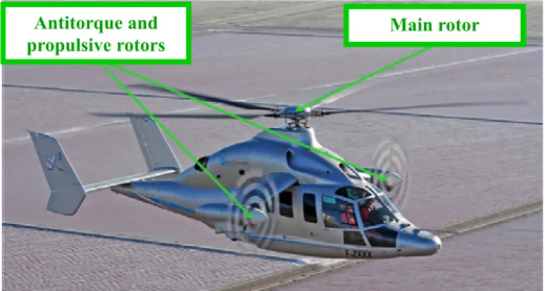
demonstrator (see figure 1).
Figure 1: picture of the technology demonstrator X3
Eurocopter has developed this hybrid aircraft in order to improve the performance of helicopters. The aim is to achieve forward speeds much higher than those usually obtained with conventional helicopters (target speed is 220 knots against 150 knots usually) at affordable costs. This aircraft combines the hover capability like a classical helicopter with the efficiency of a turboprop in cruise flight. To achieve this goal, the aircraft has, in addition to its traditional main rotor, two wings at the end of which two propellers are fitted to perform the propulsion and the yaw-axis / slip angle control of the aircraft. Maxime LECLERCQ EUROCOPTER Innovation Department ‐ ETW Etablissement de Marignane 13725 MARIGNANE FRANCE François MALBURET Arts et Metiers ParisTech ; CNRS, LSIS, 2 Cours des Arts et Metiers 13617 AIX‐EN‐PROVENCE FRANCE Philippe VERON Arts et Metiers ParisTech ; CNRS, LSIS, 2 Cours des Arts et Metiers 13617 AIX‐EN‐PROVENCE FRANCE Antitorque and
This aircraft control (antitorque / yaw-axis / slip angle / propulsion) is performed by the control of the thrust generated by its variable-pitch propellers. These propellers are fully involved in the safety, control and handling qualities of this helicopter type. In order to elaborate suitable control laws and to have a dynamic behaviour in flight compliant with the pilots’ requirements, it was necessary to develop an accurate model of the dynamic response of a propeller pitch change system. So this article focuses on a propeller pitch change mechanism and its dynamic response.
This paper presents first the specificities induced by the use of a propeller on this type of hybrid helicopter concept. These specificities explain why this study is done. Then, we will show how the models commonly used to characterize the dynamic response of helicopter rotor servo-actuators are unsatisfactory to represent the dynamic response of a propeller when we want to perform a function similar to a rotor function. After that, this article presents the phenomena applied to the propeller and their contributions to the dynamics of this subsystem. This leads to a behavioural model of the dynamic response of the pitch change mechanism. Finally, an experimental analysis of the system dynamic response and a model adjustment conclude this paper.
2. CONTEXT
This section is dedicated to the presentation of various specificities generated by the use of propellers in the control of such a type of hybrid helicopter. Some design choices of pitch change mechanism resulting from the requirements/specificities are explained here.
2.1. Application specificities
The propeller studied in this paper is a system with different specificities. Some are inherent to the propeller itself, while others are related to its use as part of a hybrid helicopter. 2.1.1. Extended working domain
In such a helicopter concept, the rotation speed of the rotor and propellers are linked. Thus, it is not possible to control the propeller thrust by rotation speed changes (as in an airplane) without affecting the main rotor thrust. The only way to master the propeller thrust is to control the collective pitch of the propellers blades. This is why variable pitch propellers are used. Propellers achieve both the function of anti-torque and slip/yaw control of the aircraft (functions traditionally performed by a tail rotor) and the function to propel the helicopter to high speeds by using only the propeller pitch variation. This implies use of an extended range of propeller pitch angle with the possibility of using the propeller out of its nominal pitch use range. The need for reverse thrust in hover and some other cases normally considered as transient in airplanes establishes the conditions in the hybrid helicopter. Moreover, as the propeller ensures the balance and the control of the aircraft yaw-axis, higher magnitude pitch variations are
potentially needed during the cruise flight. Indeed, to achieve yaw manoeuvres around trimmed configurations or slip angle control during level flight, the pitch must be dynamically changed. This will contribute to having the propellers working out of their usual bandwidth.
2.1.2. High variation of the external loads
The external loads, partially responsible for the propeller dynamic response, are functions of various parameters and are subjected to huge magnitude variations in the full flight envelope. They can potentially reach very high values.
2.1.2.1. Loads applied on the system
A propeller is subject to many various external loads [2]. Some of these loads applied to the propeller assembly do not participate at all, or very little, to the dynamics of the mechanism controlling the blade pitch angle. We will now pay specific attention to the loads involved in the pitch change dynamic. In a very simple way, we can see the control forces applied to the pitch change mechanism as primarily the result of the thrust and centrifugal force of the blades [3]. The two major components of the control load have in fact two distinct origins:
The first origin can be described as "aerodynamic" because it comes from the thrust generated by each blade. The pressure distribution along the blade will generate a moment at the blade root. This will be called "blade aerodynamic moment”.
The second origin can be described as "inertial" because it comes from the mass distribution inside the blade airfoil. Because of centrifugal force, this will generate a moment at the blade root. This will be called "blade inertial moment". In addition to this, an interaction between the aerodynamic effects and inertial effects will be added later. Under the influence of aerodynamic force, blade distortion occurs. This results in a change in the blade mass distribution from its pitch change axis. This results also in a change in the load coming from inertia.
These two major components of the blade control moment fully participate in the system dynamics. Indeed, the pitch change actuator has to act against these loads to perform any propeller pitch change. However, the aerodynamic and inertial moments of the blade are a function of various parameters and are subjected to large magnitude variations in the full flight envelope.
2.1.2.2. Blade aerodynamic moment
In this section, we are interested in the moment coming from the aerodynamic force applied on the blade. With the help of a propeller numerical calculation software developed especially for the needs of this project, the variation curves of the aerodynamic moment for different forward speeds were determined. This program performs:
¾ simulation by blade elements ¾ calculation of induced speed by:
- the method described by Adkins and Liebeck for VH≥20 m/s [4].
- the theory of Froude for VH≤20 m/s.
Note also that the aerodynamic coefficients of the blade airfoils [5] [6] were adjusted with the help of Computational Flow Dynamics tools. This allowed representation of the aerodynamic moment for different blade pitch values.
This moment is a function of the propeller rotation speed and of the incidence angle of the propeller blades (combination of propeller pitch angle and aircraft forward speed). Figure 2 shows the aerodynamic moment as a function of the propeller pitch angle for different aircraft forward speeds.
Blade aerodynamic moment variation
0.75R blade pitch angle
B lad e aero d y n a mi c mo me n t a d g m Forward Speed Increase Area + « Nose up » tendency Area -« Nose down » tendency Blade pitch angle increase
Figure 2: blade aerodynamic moment variation as a function of the forward speed
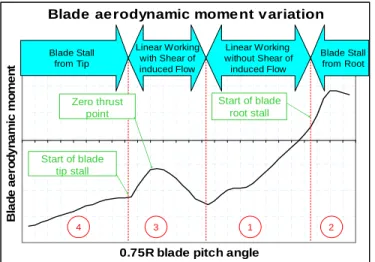
Figure 3 explains the specific variation of the aerodynamic moment as a function of the blade pitch angle.
Blade aerodynamic mome nt v ariation
-800 -600 -400 -200 0 200 400 600
0.75R blade pitch angle
B la d e ae ro d y n a m ic m o m e n t Start of blade tip stall Start of blade root stall Zero thrust point 4 3 1 2 Blade Stall from Tip Linear Working with Shear of induced Flow Linear Working without Shear of induced Flow Blade Stall from Root
Figure 3: explanation of blade aerodynamic moment variation
Different gradients along this moment variation as a function of the propeller pitch angle appear. These gradients show the different following working modes of the propeller:
¾ Area 1 : β2 < beta < β3 : : in this area, propeller thrust is always positive and all blade sections work in positive thrust for low-incidence pitch values. This range is the nominal working range for a propeller.
¾ Area 2 : β3 < beta : blade sections very close to the blade root exceed the stall incidence of a local airfoil. The associated diving moment is consequently reduced (Cm curve of the airfoil).
¾ Area 3 : β1 < beta < β2 : blade sections work always at low-incidence values but, this time, the blade root works at negative thrust whereas the blade tip works at positive thrust. Shears of the induced flow appear along the blade. ¾ Area 4 : beta < β1 : the blade tip starts to stall (the camber
accelerates the stall in negative thrust), then, the more the blade pitch angle is close to the lowest pitch value, the more the stall affects the internal blade part.
2.1.2.3. Blade inertial moment
The blade inertial moment is generated by the mass distribution of each airfoil section from the pitch change axis. Therefore this moment is a simple periodic function of the blade pitch angle. This moment depends only on the propeller rotation speed and on the propeller pitch angle (not on the aircraft forward speed as opposed to the blade aerodynamic moment).
2.1.2.4. Blade control moment
The sum of these two components has a “nose down” tendency. This shows that the resulting moment will generally tend to decrease the pitch angle value. The external forces applied to the propeller pitch change command therefore act only in one direction. Figure 4 shows the variation of blade control moment according to the blade pitch angle for different aircraft forward speeds.
Blade control moment variation
0.75R blade pitch angle
B lad e co n tr o l m o m e n t a d g m Forward Speed Increase Area + « Nose up » tendency Area -« Nose down » tendency Blade pitch angle increase
Figure 4: blade control moment variation as a function of the forward speed
2.1.2.5. Versatility of external loads
There are huge differences in the blade control moment value because of the aircraft speed and the propeller pitch value (see 2.1.2.4). The extended range of propeller pitch angle with the possibility of using the propeller out of its usual pitch range (see 2.1.1) means that the external loads encountered by the pitch change mechanism in the configuration "hybrid helicopter" can be potentially far higher than those typically encountered on airplanes.
2.2. System studied specificities
The functioning principle of a variable pitch propeller and the targeted application implied some choices/limitations in the design of the pitch change mechanism.
2.2.1. Asymmetric functioning
Propeller pitch change mechanisms are controlled by actuators using electric or hydraulic power (some others are also controlled directly by muscular force). Different types of hydraulic actuators are available. But, as the external loads applied to the propeller pitch change mechanism only act in one direction (see 2.1.2.4), a single acting hydraulic actuator has been chosen. This actuator type is widely used to control the pitch change mechanism of a variable pitch propeller [7]. With such a mechanism, the pitch change in one direction (pitch increase direction for example) is performed hydraulically while the movement in the opposite direction (pitch decrease direction for example) is provided mechanically (often with the help of one or several springs) and the external loads acting on the blade. Thus, these mechanisms clearly function asymmetrically.
2.2.2. Location of pitch change system components On a helicopter rotor, the whole of the system delivering the required power to ensure the pitch change (piston/governor/hydraulic circuit) is located in a non-rotating axis. On a propeller, this power system is split into two different axis systems. Concretely, the piston is directly integrated in the hub (rotating axis system) whereas the governor and the hydraulic circuit are located in the fixed aircraft fuselage axis system.
2.2.3. Servo control design choice
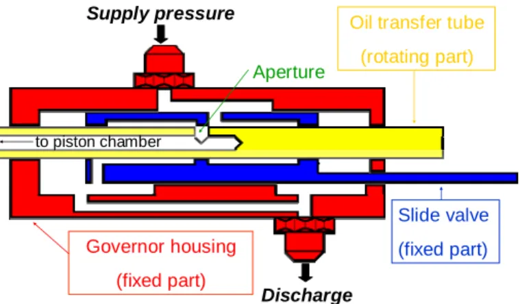
The pitch change mechanism is controlled hydraulically by a governor. This governor ensures the oil transfer between parts in fixed axis system and parts in rotating axis system. A slide valve enables the governor aperture to open and to connect the piston chamber (rotating axis system):
¾ either with the supply pressure source (fixed axis system). ¾ either with the discharge (fixed axis system).
Figure 5 shows the governor functioning principle ensuring the propeller pitch change.
Oil transfer tube (rotating part) Governor housing (fixed part) Slide valve (fixed part) Aperture Supply pressure Discharge to piston chamber
Figure 5: governor functioning principle
This connection is done by using a rotating pipe (oil transfer tube) in which an aperture is drilled. This tube is mechanically connected to the piston. Therefore, any piston displacement leads to an equivalent tube displacement. The governor aperture opening can:
¾ either fill the piston chamber with pressurized oil. ¾ either empty the piston chamber
The piston displacement causes the tube displacement. This displacement occurs up to the closure of governor aperture (balance position). This is a position control.
2.2.4. System stabilized by internal leakages
The axis systems change as a result of piston location in the hub (see 2.2.2), which imposes a clearance between rotating and fixed parts to avoid jamming between these parts and to take into account the material thermal dilatation. This diametric clearance between governor parts ensures oil transfer and generates an internal leakage. In order to reduce this leakage and to have a stable system, the overlap is larger than the aperture size (positive overlap).
The leak occurring at cylindrical clearance level in the case of laminar flow is given by the following equation [8]:
P ). )² 2 / ( ² 2 3 1 ( L D.J 1 96 Q 3 Δ + = J ε νρ π
with : Q the leakage flow (cm3/s)
ν the kinematic viscosity (mm²/s) ρ the fluid density (g/cm3)
D the shaft diameter (cm) J the diametric clearance (cm) L the leakage flow length (cm)
P
Δ the pressure drop (kg/cm²)
ε the axis offset (distance between shaft and hole axis)
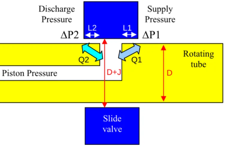
This equation is not always experimentally checked but it gives an idea of how the different parameters are related. Figure 6 presents the area ensuring the pitch change actuator control and stabilization.
Figure 6 : governor distribution area (aperture/overlap) In this design, there are two internal leakage areas: ¾ leakage between supply pressure and piston (Q1) ¾ leakage between piston and discharge (Q2)
P1
Δ and P2Δ represent the pressure drop respectively between Supply pressure and Piston pressure and between Piston pressure and Discharge pressure. L1 and L2 represent the overlaps respectively at Pressure side and at Discharge side. To have such a system stabilized by internal leakages, the incoming flow Q1 has to be exactly equal to the outgoing flow Q2. The hypothesis that parameters D, J, ν, ρ and αare identical on each side of the governor aperture can be made. The following equation is found:
2 2 1 1 L P L P =Δ Δ
2.2.5. Supply pressure / flow limitations
The change of axis systems because of piston location in the hub (see 2.2.2) imposes a supply pressure limitation in a propeller. This is due to sealing technological limitations between rotating and fixed parts. By taking into account that the hydraulic system has to deliver high loads to counter the spring and blade control loads with limited supply pressure level, it is necessary to have a piston with a large section. Consequently, the hydraulic flow required to change propeller pitch is much higher than the flow required by a helicopter rotor actuator to change the pitch.
After the presentation of the phenomena applied to the propeller, we will focus specifically on modelling of the system dynamics by analyzing the existing models and their insufficiencies.
3. STATE OF THE ART
Studies concerning the development of variable pitch propellers are relatively ancient and the major improvements in this domain are the results of experiments. Pierre Levasseur claimed to have successfully tested a variable pitch propeller for the first time at the Paris Airshow in 1921 [9].
3.1. Aircraft propeller dynamic model
The issue of the dynamic response of propeller pitch change mechanisms is not often discussed because there is no real requirement concerning the dynamic control of theses systems in airplanes. Indeed, in most cases, the pitch change control of an airplane variable pitch propeller could be summed up as a "2 positions" command. Indeed, the pilot uses low pitch for takeoff. He then increases the pitch (high pitch) to achieve optimal performance in cruise. Finally, he reduces again the pitch (low pitch - or reverse thrust to brake) for the landing. The pilot does not permanently vary the propeller pitch during flight.
This issue of the dynamics of propeller pitch change control applied to an airplane is however studied in the case of "constant speed propellers" (propeller regulating the blades pitch by itself as a function of the rotation speed to maintain optimal power consumption during cruise). But input order magnitudes and associated response times required are far from being comparable with those required to perform a function as critical as the anti-torque and yaw/slip control [10]. In addition, the pitch change dynamic response of this propeller type is analyzed by coupling with the dynamic response of the rotation speed regulator. Such modelling cannot be used for applications functioning at constant rotation speed and with high magnitude inputs.
3.2. Helicopter servoactuator dynamic model
A conventional servoactuator, such as that used to control the helicopter rotor blade angle, behaves theoretically as a second-order system. This is because it meets the fundamental principle of dynamics which is described by a second-order equation. However, it is observed practically that a servoactuator can be well modelled by a first-order system [11,12]:
y output variable (displacement)
u input variable (displacement)
K system gain
τ the time constant
3.3. First-order system representation insufficiencies This first-order model seems to be compliant with the requirements for modelling raised by the application to a hybrid helicopter. However, this representation has some insufficiencies that are detailed hereafter.
3.3.1. Functioning range is wider
The majority of modelling considers only of small inputs around a position (small volume changes, transient mode). These first-order models consider only of small loads. But in the case of propeller control of a helicopter hybrid
¾ The input can sometimes be of small magnitude, but also sometimes quite large magnitude.
¾ Loads can be very high because of the existence of significant control loads.
Supply Pressure Piston Pressure Discharge Pressure Q1 Q2
P1
Δ
L1 L2 D D+JP2
Δ
Rotating tube Slide valve .p 1 K Input Output U(p) Y(p) τ + = =3.3.2. No speed saturation representation is possible With a simple first-order model, it is not possible to represent system speed saturations. These speed saturations can come from two causes.
3.3.2.1. Speed saturation due to flow saturation
Speed saturation could occur for fast and high-magnitude input signals (corresponding to a prolonged large governor aperture opening). In such a case, the needs for system oil flow consumption could reach the pump flow capacities and/or the flow through hydraulic pipes could be higher than the capacity of the hydraulic pipes to transport oil. This results in saturation of the system speed as a result of flow saturation.
3.3.2.2. Speed saturation due to hydraulic actuator maximal speed under loads
Speed saturation could also occur for high values of external loads. Indeed, the existence of significant control load has an impact on the maximal reachable response speed of the hydraulic actuator. By starting from the expression relating the maximum flow rate and pressure drop through an aperture with small thickness in steady state and knowing that the force developed by the piston is given by the product of the pressure differential between the pressure in the piston chamber and the supply pressure multiplied by the piston section, it is possible to plot the maximal speed reachable by an actuator under given loads [11,12]. This model is easily verified experimentally.
Figure 7 : load-Speed diagram of a hydraulic actuator Using the example given in figure 7, we note that:
¾ if the external load varies within the low load domain (range in green), the maximum output speed is moderately affected (50% of this “load” range representing only 30% of the “speed” range).
¾ if the external load varies in the field of high loads (range in red), the impact on the maximal output speed is much higher (20% of this “load” range representing nearly 50% of the “speed” range).
Therefore, it is clear that for a given hydraulic configuration, the actuator output speed will be very different depending on the external forces applied to it. External forces are highly versatile in the full flight envelope. Consequently, the maximal response speed of a pitch change mechanism will also be highly variable.
3.3.3. Response time is a function of the speed and magnitude of the input order
A first-order model could be also insufficient for another reason. It is possible that the time constant associated with the response depends on the speed and magnitude of the order. These hypotheses are partly due to the existence of an overlap in the governor and because of the system stabilization in a given position by internal leakages of the governor. The time constant could be very different depending on where the input command occurs:
¾ The aperture is fully opened. The response time is then very quick (with response speed saturation).
¾ The aperture is partially opened. The response time is then moderately quick.
¾ The aperture is covered and system response is made only by internal leakages. The response time is then rather slow.
3.3.4. Stabilized position is function of external loads The pressure drop ΔP of the propeller pitch change system depends on external loads (because it depends on piston chamber pressure achieving a balance with external loads). For a given position order, the balance position of this system will change according to external conditions (see 2.2.4):
¾ if ΔP1>>ΔP2 then L1>>L2. ¾ If ΔP1<<ΔP2 then L1<<L2.
By considering the command aspect, this system presents inaccuracies because of its “variable” balance position. Indeed, for the same control position (slide valve position), the system balance position (aperture position from the slide valve) can be different depending on external conditions, as shown in figure 8.
It is not possible to represent a balance position "variable" with the help of a first-order system. However, accurate knowledge of the system output value is extremely important in control by the Autopilot Flight Control System. Consequently, this phenomenon has to be represented.
Load-Spe e d Diagr am 0 2 4 6 8 10 12 14 0 .0 2 0 0 0 .0 4 0 0 0 .0 6 0 0 0 .0 8 0 0 0 .0 10 0 0 0 .0 12 0 0 0 .0
Exte r nal Load
O u tput S p e e d Fmax No Load Speed
Vmax Low Loads Envelope
Area where external load variation does not affect a lot the system dynamics
0
High Loads Envelope Area where external load variation affects a lot the system dynamics
High external loads case Supply Pressure Piston Pressure Q1 Q2 P1 Δ
P2
Δ
Discharge PressureSmall external loads case
Piston Pressure Q1 Q2 P2 Δ
Δ
P1
Discharge Pressure Supply PressureFigure 8 : example of different stabilized configurations 3.3.5. Asymmetric system representation is impossible
with a simple first-order system.
The system functions asymmetrically. This asymmetry can not be represented by only one first-order system, but requires at least two first-order systems: a first-order system for one input order direction and another first-order system for the other input order direction.
After analysis, we have noted:
¾ Insufficiencies and limitations of existing models (first-order or higher-(first-order systems) to represent finely the dynamics of a propeller pitch change mechanism used in the specific conditions of a hybrid helicopter environment. ¾ The importance of external loads in the dynamic response
of this system,
Thus, in the following section, a new model is described that represents these specific phenomena. It was developed to meet the multiple issues:
¾ System functioning asymmetrically.
¾ “Variable” balance position for a same input order position according to external conditions.
¾ Response time constant (τ variable) and response speed (saturation speed) dependent on the input order.
¾ High versatility of external loads.
4. MODELLING
A first-order system model is appropriate for a conventional servoactuator. However for all the reasons previously stated, this model is too simple to represent all the expected phenomena (see 3.3). This section presents a model proposal which is configurable and able to represent all the phenomena.
4.1. Modelling basis
The modelling basis remains a first-order model. However, because of the system asymmetry, it is necessary to have 2 first-order system behaviours (see 3.3.5).
4.2. First-order system with speed saturation
As a result of flow rate saturation and / or because of the external load impact on the maximal speed reachable (see 3.3.2.2), it was decided to add speed saturation to the response of this first-order system.
Thus, for each infinitesimal time dt, we calculate the speed obtained by the first-order system considered alone. If this speed exceeds (in absolute value) a critical speed, we impose this critical speed. This latter is imposed until the speed obtained by the first-order system alone no longer exceeds the defined critical speed. Then, the system behaviour again becomes identical to first-order system behaviour.
This model is still not satisfactory to represent the phenomena:
¾ “Variable” balance position according to external loads. ¾ Response time constant dependent on the input order.
Moreover, this model always requires 2 first-order system models. To solve these problems, in addition to the speed saturation condition, application of a variable time constant is suggested.
4.3. First-order system with speed saturation and variable constant time
For this purpose, dependence between the time constant and the governor aperture opening is created. At each instant, the governor aperture opening is calculated by the difference between input and output. A time constant is associated with each aperture opening width. This variable is then reported in the first-order model with saturation described above at each calculation step.
This modelling type requires therefore provision of a curve giving the time constant τ as a function of the governor aperture opening. The null aperture opening is represented by the alignment of the middle axis of the total overlap area (overlap supply pressure side + overlap discharge side) with the aperture axis. The opening area of the orifice is discretized to define this law of variable time constant τ. Then, a value of τ is assigned to each boundary of each interval. Between each of these terminals, a linear interpolation is performed. Figure 9 shows an example of a variable constant time law.
Time Constant τ Variation Aperture Opening T im e C ons ta nt τ
Axis representing the null aperture opening
Virtual axis representing the aperture closed Time constant values
for “mirror” aperture opening values Interval boundaries Linear interpolation between interval boundaries Interval representing the
governor total overlap
Figure 9: time constant variation law as function of the governor aperture opening (simulating a “variable”
balance position)
The y-axis values choice of each interval boundary of this law is used to represent accurately:
¾ Functioning of an asymmetric system. This is necessary to create an asymmetric law with different time constant values τ on both sides of the null opening (see figure 9 – time constant for opening value “i” is different from the time constant of its “mirror” opening value “-i”).
¾ A system with a variable response time according to the different aperture opening values. This is necessary to create a non-constant law with time constant values τi different for each aperture opening (see figure 9).
¾ A system with a “variable” balance position as a function of external loads for a same control position. This is necessary to create a time constant variation law that is not centred on null aperture opening (to represent a non-identical overlap on both aperture sides – see figure 9). It is noteworthy that this balance position is fictional. After a certain time (time depending on τ values given in the overlap area), without input order, the system will still stabilize itself at the null opening position. This is not the case in reality. But, for permanent “dynamic” inputs (case of the target application), this modelling defect is not perceptible.
This first-order model with variable time constant and with speed saturation makes it possible to fully represent all the phenomena expected to apply to the system studied here. For example (see figure 10), a system with a strongly pronounced asymmetrical functioning (fast in the increase direction - slow and saturated in the decrease direction) can be represented.
System transfer function identification
38.5 39 39.5 40 40.5 41 41.5 10 10.2 10.4 10.6 10.8 11 11.2 11.4 11.6 11.8 12 time [s] D ispl a ce m e n t [ m m ]
input (actuator control rod displacement) output (betatube displacement)
Figure 10 : example of temporal curves (input and output) obtained with the developed modelling.
Finally, this time constant variation law can be configured as a function of the variables acting on the external forces. These parameters are:
- Propeller Blade Pitch Angle - Aircraft speed
- Propeller Rotation Speed - Air Density
- Oil Temperature
Thus, a parametric function delivering a τ value can be established for each aperture opening interval boundary.
To conclude this section, this behavioural modelling is easy to use and adjustable for all kind of situations.
5. EXPERIMENTAL ANALYSIS 5.1. Test rig description
A test rig principle and its instrumentation implementation are described below in figure 11.
Figure 11: test rig principle and instrumentation This test rig was developed in order to:
¾ study the pitch change mechanism of a conventional airplane propeller. Displacement Sensor (input) Flex-ball command (input order) Governor “LASER” Displacement sensor (output) Hydraulic Supply Hydraulic Drain
¾ check the existence and the impact on the system dynamics of the phenomena due to the application specificities.
¾ adjust the behavioural model.
¾ deduce and adjust the pitch change mechanism to have transfer function compliant with the specificities imposed by the intended application.
5.2. Preliminary results
Preliminary results have confirmed the trends of a system that functions asymmetrically and very variably.
The “nose down tendency” effects generated aerodynamic and inertial moments of the blades affecting the pitch change mechanism dynamics can be easily observed during tests performed, at first, without propeller rotation and, then, with propeller rotation (that is to say respectively with and without aerodynamic and inertial moments of the blades).
The results of such a test are respectively shown in figure 12 and figure 13.
In figure 12, we see that the pitch increase is fast (nominally performed by the hydraulics and with very little external effort to overcome – just the spring load contribution) while the pitch decrease is not very fast (because it is made by the spring only). The input order in this test is a high-magnitude step input. This test is not fundamentally relevant for our behavioural model because it does not represent a real functioning case (no rotation of the propeller), but it substantiates that the choice of an asymmetric modelling is judicious.
Propeller pitch angle dynamic response
Time
Propeller pitch angle
input output
Figure 12: test without external load (without rotation) In figure 13, we see that the propeller pitch change response follows far more the input order as previously (in both directions). The input order in this test is a quite high-magnitude sinusoidal signal and performed with propeller rotation. The difference with the previous test is simply due to the presence of the external load (propeller rotation means the presence of aerodynamic and inertial moments of the blades). Note that it was not possible to test a large-magnitude step input resulting from the involved power variations. Test inputs
were therefore restricted to magnitudes compliant with the power consumption levels existing during flight.
Propeller pitch angle dynamic response
Time
Propeller pitch
angle
input output
Figure 13: test with external load (with rotation) 5.3. Dynamic response tests results
Both previous tests were performed with slow input orders. With such tests, it was not possible to observe the effects of important external load variations on the dynamics of the pitch change mechanism. For this purpose, others tests were made with faster and more “dynamic” input orders. In both following tests, a similar input order signal (identical magnitude and frequency sinusoidal signal) was performed but it was performed around two different mean pitch values.
In the first case (figure 14 – performed with a null thrust), the dynamic response is almost identical in both directions (pitch increase and decrease).
In the second case (figure 15 - performed with a positive thrust), the dynamic response is no longer the same in both directions (pitch decrease is faster than pitch increase). These differences are due to the increase in external forces while the hydraulic loads remained constant.
Propeller pitch angle dynam ic response
Time P ropel le r pi tc h angl e input output
Propeller pitch angle dynam ic response Time P ropel le r pi tc h angl e input output
Figure 15: test with external loads (with rotation) 6. IDENTIFICATION - MODEL ADJUSTMENT
Various pitch change tests were performed on the test rig. These were used to determine accurately the time constant variation law and to identify the first elements enabling the parametric functions development. The results obtained with this first-order model with variable time constant and speed saturation appear to be satisfactory as shown in figure 16.
Comparison of responses under different magnitude step inputs
Time D isp la ce m e n t input output model
Figure 16: Comparison of Model and Experiments responses under different magnitude step inputs 7. CONCLUSION
A propeller pitch change mechanism is subject to many phenomena that impact on its dynamics. According to the first experimental results, the behavioural model presented in this paper, based on a first-order system and with variable response time and speed saturation, seems to give satisfactory results in modelling the dynamic response of the actuator pitch change. This model enables the effects of different phenomena to be represented that are applied to a variable pitch propeller used to control a hybrid helicopter concept like X3:
¾ System functioning asymmetrically
¾ Balance position variable as a function of external loads conditions for the same control position.
¾ Response constant time and response speed (speed saturation) as a function of input order.
¾ Effects of high variations of the external forces.
8. PERSPECTIVES
The test rig only enables testing of the hover configuration. Flight tests will complete this behavioural model and confirm its validity or not on the full flight envelope.
These propeller tests on the test rig have also demonstrated that a conventional variable pitch change propeller has a limited dynamic response. Some improvements are requested to be compliant with the hybrid helicopter control requirements. Other models based on MatLab Simulink / AMESIM tools have enabled identification of some geometric parameters restricting the dynamics. The dynamic improvement of a propeller pitch change system can be beneficial for the airplane industry not only in the field of aerobatics but also in civil aviation.
A reduction of blade control load could also improve the dynamics of propeller pitch change mechanisms. A usual method to reduce control loads consists of adding counterweights. However, as the mass is a critical issue in helicopters more than in any other application, a control load reduction by blade design optimization could be a better solution.
ACKNOWLEDGMENTS
This work has been supported by Eurocopter’s Innovation department, Marignane, FRANCE.
REFERENCES
[1] Padfield, G., “Helicopter flight dynamics”, ed Blackwell science, 1996
[2] Borst H., Summary of propeller design procedures and data - volume1 - Aerodynamic design and installation, Nov 1973
[3] Amatt W., Bates W., Borst H., “Summary of propeller design procedures and data - volume2 - Structural analysis and blade design”, Nov 1973
[4] Adkins C., Liebeck R., “Design of Optimum Propeller”, Journal of propulsion and power Volume10 (5), Sept.-Oct.1994
[5] Abott I., Von Doenhoff A., “Theory of wing sections including a summary of airfoil data”, Dover publications Inc., New York, 1958
[6] Hoerner S., Borst, H. Fluid-Dynamic Lift, Hoerner Fluid Dynamics, Bricktown, New Jersey, 1975
[7] Kroes M., Wild, T., “Aircraft Powerplants”, seventh edition, McGraw-hill international editions, 1994
[8] Guillon M., “Commande et asservissement hydraulique et électrohydraulique”, Lavoisier, 1992
[9] Levasseur P., “Flight” November 17th 1921
[10] Sand E., Elliott D., Borst H., “Summary of propeller design procedures and data - volume3 – Hub actuator and control designs”, Nov. 1973
[11] Blackburn J.F., Reethof G., Shearer J.L., “Fluid Power Control”, John Wiley, 1960
[12] Merritt, H.E., “Hydraulic Control Systems”, John Wiley & Sons, New York, New York, 1967