Science Arts & Métiers (SAM)
is an open access repository that collects the work of Arts et Métiers Institute of
Technology researchers and makes it freely available over the web where possible.
This is an author-deposited version published in: https://sam.ensam.eu Handle ID: .http://hdl.handle.net/10985/14715
To cite this version :
Taoufik QORIA, François GRUSON, Frédéric COLAS, Guillaume DENIS, T. PREVOST, Xavier GUILLAUD - Inertia effect and load sharing capability of grid forming converters connected to a transmission grid - In: The 15th IET international conference on AC and DC Power Transmission, Royaume-Uni, 2019-02-05 - n/a - 2019
Inertia effect and load sharing capability of grid forming
converters connected to a transmission grid
T. Qoria*, F. Gruson*, F. Colas*, G. Denis
†, T. Prevost
†, X. Guillaud*
* Univ. Lille, Centrale Lille, Arts et Métiers Paris Tech, HEI,
EA 2697 - L2EP - Laboratoire d’Electrotechnique et d’Electronique de Puissance, F-59000 Lille, France
†Réseau de Transport d’Electricité, Versailles, France
taoufik.qoria@ensam.eu
Keywords: Grid-forming converter, improved droop control, inertia emulation, active power dynamic, power sharing capability.
Abstract
The virtual synchronous machine concept (VSM) has been developed initially to reproduce the synchronous machine stabilizing effect by providing inertia with the emulation of swing equation, whereas droop control is developed initially to ensure load sharing and has no inertia. An introduction of a low pass filter to droop control has been motivated to filter the active power measurement and ensures a time decoupling with the inner control loops, whereas, this low-pass filter can also provide inertia to the system. This functionality is limited due to its negative impact on the active power dynamic. This paper proposes an analysis of the conventional droop control by showing its limitations and proposes an improved inertial droop control that allows providing the inertia to the system and ensures a good dynamic behavior of the active power at once in simple manner, and without modifying the load sharing capability. The results obtained are compared to the conventional method (Droop control and VSM) in various topologies in order to show the relevance of the proposed method.
1 Introduction
Electrical machines have the physical property of storing kinetic energy in their mechanical part; this energy contributes essentially to the stability of the electrical grid. In case of failure, the inertia is able to compensate immediately the power imbalance and limits the frequency variations which help the system to remain stable.
In recent years, renewable energy sources have been steadily increasing, these latter are interfaced to the AC system through power converters. Currently these converters are controlled to inject active and reactive power by relying on the voltage formed by the AC grid; this control strategy is well-known as grid-following control.
_______________________________________________ This project has received funding from the European Union’s Horizon 2020 research and innovation program under grant agreement No 691800. This paper reflects only the author’s views and the European Commission is not responsible for any use that may be made of the information it contains.
A rise of renewable energy sources based on grid-following control causes a significant reduction of the total electrical grid inertia [1]. It induces a faster dynamic response of the frequency since they do not naturally bring this inertia effect [2]. Therefore the reaction time of the primary control becomes slower than the frequency response time which may lead to an unstable operation. This low-Inertia phenomenon is already noticed in several areas, such as Ireland and UK. More details about those data are published by ENTSOE [3]. It is possible to modify the active power with respect to the derivative of the frequency to mimic the inertial effect. But this supposes to measure the frequency and operate a derivation which may induce some time delay and frequency oscillations [2], [4].
Because of these limitations, new control laws are needed in order to emulate the inertia effect. This subject has been widely discussed in the literature, which has led to the development of the grid forming control[5]- [6] that induces more natural inertia effect linked with the way to synchronize the converter to the grid. This has been largely documented on various publications dealing with virtual synchronous machine, synchronverter, virtual synchronous generator (VSG) or VISMA [7]–[13]. Some of these concepts emulate the electrical behavior of the real synchronous machine in order to enhance the load sharing transient; others imitate the stabilizing effect by reproducing only the swing equation effect. The virtual synchronous machine concept has been developed also to ensure a self-synchronization to the main AC grid [11].
From another side, the principle of the droop control is also linked with the synchronous behavior of synchronous generators. Lots of classical synchronous generators have a static droop control that adjusts their mechanical power injection with respect to the frequency variation, and thus compensate for power unbalance. The static proportional relationship between power and frequency creates a mechanism of load sharing between generation units. This effect can be reproduced by the droop control applied to the grid forming converter, this concept has been widely discussed in the context of micro-grids [14]–[17] and uninterruptible power supply [18], [19]. The droop control is also known in the literature as Power Synchronization Method (PSM) [20]. The droop control principle has been developed for a variety of applications. Then, it has been improved in order to achieve a good decoupling between active and reactive power, to guarantee an accurate reactive
power sharing by introducing virtual impedances, and also to ensure a good transient behavior by filtering the oscillations around the grid frequency [20].
Although conceptually these two concepts are used for different reasons .i.e. droop control ensures the power sharing between units in parallel operation, while VSM provides inertia and damping; it has been shown in this context that the two approaches are mathematically equivalent [21]. In some papers the load sharing using the VSM concept is ensured by an extra loops, thus the model become more complex and require additional loops [8], [22]–[24].
This paper aims to combine the inertial effect of a VSM and the load sharing capability of a droop control in a single algorithm without adding any more loops or complexities. In this paper, small-signal model for conventional droop control is presented in order to show its limitations and propose a new simple control strategy that provides inertia; ensure a better active power transient and load sharing. In order to simplify the study, only the average VSC model is used in the development and the DC bus is considered as an Ideal DC voltage source.
The inertia effect will be analyzed, improved and simulated in various grid topologies (e.g. grid connected mode and parallel mode).
The reminder of this paper is structured as follows. In Section.2, a mathematical comparison between droop control and VSM is presented with reference to the shortcomings of droop control. Section.3 presents the proposed inertial droop control with its design method. Section.4 shows a comparative synthesis between the proposed method and conventional control techniques.
2 Droop control and VSM comparison
2.1 Recall on classical algorithms
The choice of the droop control is motivated by its capacity to interact with other units without dedicated communication link. The architecture is presented in Figure 1. This controller is responsible for power regulation and load sharing through the parameter 𝑚𝑝 which defines the maximum variation of
the frequency for a nominal power of the AC source. Usually the droop control gain is set to 5%. This means that for a maximum variation of the active power, the frequency will decrease by 5%.
Figure 1: Droop control.
A low-pass filter is often added on the power measurement or on the frequency derivation as shown in figure 1 for dynamic decoupling with inner loops, active power noises filtration, and to avoid frequency jump.
The architecture of the VSM is presented in figure 2. This concept is mainly chosen because it reproduces the synchronous machine stabilizing effect by introducing inertial effect of the synchronous machine. More complex models have been also developed to mimic also the electrical behavior of the synchronous machine as mentioned in the introduction.
Figure 2: VSM for virtual inertia and damping 2.2 Mathematical equivalence
The transfer function of the droop control is expressed in per-unit as follow: 1 𝜔𝑐𝑚𝑝𝜔𝑉𝑆𝐶̇ = 𝑝 ∗− 𝑝 𝑚𝑒𝑠− 1 𝑚𝑝(−𝜔𝑠𝑒𝑡+ 𝜔𝑉𝑆𝐶) … + 1 𝜔𝑐𝑚𝑝𝜔𝑠𝑒𝑡̇ (1)
Where 𝑝 ∗, 𝜔𝑠𝑒𝑡 and 𝜔𝑉𝑆𝐶 are respectivey the set-point active
power, the set-point frequency and the output converter frequency.
Note that the red expression in the equation above can be neglected as the set-point 𝜔𝑠𝑒𝑡 is constant.
The transfer function of the VSM is expressed in per-unit as follow:
2𝐻𝜔𝑉𝑆𝐶̇ = 𝑝∗− 𝑝𝑚𝑒𝑠− 𝐾(−𝜔𝑠𝑒𝑡+ 𝜔𝑉𝑆𝐶) (2)
Where 𝐻 and 𝐾 are respectively the inertia constant and damping coefficient, while 𝜔𝑠𝑒𝑡 can be a constant frequency
set-point or a grid frequency estimation depending on the mode operation (i.e. power regulator of frequency regulator) Equivalence between both approaches exists and can be expressed by:
2𝐻 = 1
𝜔𝑐𝑚𝑝 ,
1
𝑚𝑝= 𝐾 (3) However, the aim of these two approaches is slightly different. The VSM is mainly focused on bringing an inertial effect to the grid. The 𝐻 coefficient is chosen first (e.g. 𝐻 = 5s) and then the 𝐾 coefficient is choosen to give a stable behavior.
From the analogy between equations (1) and (2), it is clear that the droop control can provide inertia such as VSM thanks to the low-pass filter dynamic where the inertia constant can be tuned through the decrease of the filter cut-frequency 𝜔𝑐.
While the decrease of 𝜔𝑐 induces oscillations on the active
power. In [25], 𝜔𝑐 must fulfills the following condition to
maintain a stable operation: 𝜔𝑛
20 < 𝜔𝑐< 𝜔𝑛
Hence, with the classical parameters, the inertia provided by this control is limited to 𝐻 = 0.2𝑠. If more inertia is needed, these approaches need to be improved.
3 Proposed inertial droop control
In control theory, a derivative action aims to stabilize the system and to control the undesirable overshoot; however a lead-lag filter is generally used to overcome the numerical issue linked to the derivative computation.
The proposed idea is to add a lead-lag controller on the active power measurement in order to damp the active power oscillations. The expression of this lead-lag action is presented in (5).
𝐶(𝑠) =1+𝑁𝑇1𝑠
1+𝑇1𝑠 (5) The interval of 𝑁 should not be chosen too high in order to ensure a proper operation in practice and to avoid soliciting much derivative action.
Figure 3: The proposed inertial droop control
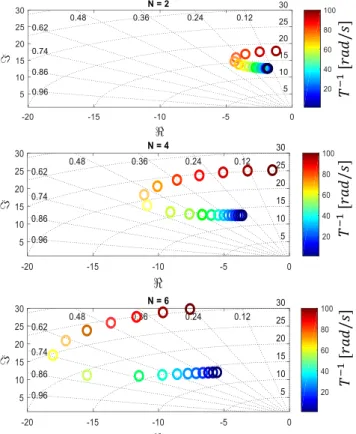
To tune the lead controller, the root-locus method based on sensitivity analysis is used. A linear model in equation 6 has been developed for the system presented below:
Figure 4: Grid-forming VSC connected to an infinite bus. The system contains 5 state variables which are respectively the grid currents dynamics, the converter output frequency, the converter angle and the filter active power measurement.
𝑥 = [Δ𝑖𝑔𝑑 Δ𝑖𝑔𝑞 Δ𝜔 Δ𝜃 Δ𝑝𝑓 ] 𝑇 , 𝑢 = [Eset 𝑝∗] 𝐴 = [ −𝑅𝑐 𝐿𝑐 𝜔𝑏 𝐼𝑔𝑞0 𝑉𝑔𝑑0𝑠𝑖𝑛𝛿0− 𝑉𝑔𝑞0𝑐𝑜𝑠𝛿0 𝐿𝑐 0 −𝜔𝑏 −𝑅𝑐 𝐿𝑐 −𝐼𝑔𝑞0 𝑉𝑔𝑑0𝑐𝑜𝑠𝛿0+ 𝑉𝑔𝑞0𝑠𝑖𝑛𝛿0 𝐿𝑐 0 0 0 −𝜔𝑐 0 − 𝑚𝑝𝜔𝑐 𝑃𝑛 0 0 1 0 0 −𝑁𝐸𝑠𝑒𝑡𝑅𝑐 𝐿𝑐 +𝐸𝑠𝑒𝑡 𝑇1 𝑁𝐸𝑠𝑒𝑡𝜔𝑏 0 0 − 1 𝑇1 ] 𝐵 = [ 1 𝐿𝑐 0 0 0 0 𝑚𝑝𝜔𝑐 𝑃𝑛 0 0 𝑁𝐸𝑠𝑒𝑡 𝐿𝑐 0 ] , 𝐶 = [ 1 0 0 0 0 0 1 0 0 0 0 0 1 0 0 0 0 0 1 0 0 0 0 0 1] , 𝐷 = [0] (6)
The analysis will be interested only on dominant oscillatory modes shown in Figure 5 for 𝜔𝑐= 2𝑟𝑎𝑑/𝑠 that corresponds
to 𝐻 = 5𝑠.
Figure 5: Lead-lag controller design
Using an iterative variation of the controller parameters, the obtained results in figure 5 show that for a given lead-lag controller frequency variation 𝑇1−1=[1 60] rad/s range, the
active power modes become more damped when the value of 𝑁 increases. It means that the proposed control improves widely the active power dynamic for large inertia constant H=5s. A comparison between modes related to active power dynamic with and without lead-lag controller is presented in the table.1.
Table 1: The active power dynamic improvement Inertia constant H = 5s
Droop with LP filter Proposed Droop control
𝜆3−4= −0.977 ± 12.5𝑖 𝜆3−4= −12 ± 10.9𝑖
ζ = 0.078 𝛇 = 𝟎. 𝟕𝟒
The improvements brought by the developed control are checked with time domain simulations in figure 6. A step on the active power (𝑝∗= 0.4𝑝𝑢) is applied at t =1s.
𝑇 − 1 [ 𝑟𝑎𝑑 /𝑠 ] 𝑇 − 1 [ 𝑟𝑎𝑑 /𝑠 ] 𝑇 − 1 [ 𝑟𝑎𝑑 /𝑠 ]
Figure 6: comparison of active power dynamics between conventional droop control and the proposed droop control.
(a) VSC Frequency, (b) Active Power System parameters: 𝜔𝑠𝑒𝑡= 1𝑝𝑢 ; 𝜔𝑏 = 2𝜋𝑓𝑛, 𝑚𝑝=
0.05𝑝𝑢, 𝑉𝑔= 𝐸𝑔= 1𝑝𝑢, 𝑅𝑐= 0.009 𝑝𝑢, 𝐿𝑐 = 0.2𝑝𝑢, 𝑁 =
6𝑝𝑢, 𝑇1−1= 55𝑟𝑎𝑑/𝑠
The next section presents a modified AC grid model with variable frequency that behaves similarly to the traditional synchronous machine response in order to show the active power dynamic, load sharing and the inertia contribution of the proposed control.
4 Comparison with other control techniques
Till now, the frequency of the voltage source modelling the grid has been considered as fixed. In this section, a variable
frequency is considered in order to assess the behavior of this source with respect to frequency variation. The studied system is presented in figure 7. The rated power of the converter and the grid are considered identical (50% Power Electronics integration). The system parameters are described in Table 2.
The objective of this test case is to validate the proposed method and to compare it with other control strategies by showing the frequency variation; load sharing and the active power dynamic (e.g. load variation for different nominal power of the converter and the equivalent AC grid).
The AC grid frequency is driven by a model representing a kind of simplified equivalent synchronous machine with a droop control. Where 𝑅, 𝐻, 𝑇𝑁 and 𝑇𝐷 are respectively the
droop gain, the inertia constant, the lead time constant and the lag time constant. The lead-lag component aims to reproduce the synchronous machine frequency dip behavior.
Figure 7: Controlled voltage source connected to an infinite AC grid with variable frequency
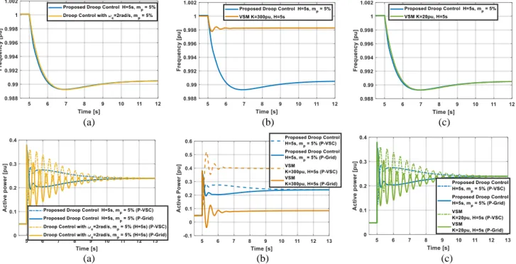
(a) (b) (c)
(a) (b) (c)
Figure 8: Comparison of the proposed method to conventional ones (a) Conventional droop control with H=5s
,
(b) VSM with high damping coefficient , (c) VSM with a small damping coefficient equivalent to the droop gain.(𝑎
)
(𝑏
Table 2: System parameters PVSC n= 1GW Linelenght= 20km Lc= 0.15pu Eg= Vg= 640kV Rc = 0.005pu PGrid= 1GW Rlne = 0.03 Ω/km Lg= 0.15pu Xline= 0.3 Ω/km Rg= 0.005pu Cline= 10−9 F/km TN= TD/2 = 1pu ωc= 2 rad/s T1= 55rad/s H = 5s N = 6pu
The developed control is compared to the control strategies of figures 1 and figure 2. In simulations of figure 8, a load variation is applied at t=5s.
In figure (8.a), the conventional droop is parametrically adapted to obtain an inertia constant of 𝐻=5s. In these conditions, the conventional droop control shows a good frequency response and power sharing in steady state, however, the active power dynamic remains very oscillatory. Comparing to the proposed method, this latter ensures at once a good active power dynamic, power-sharing capability and inertia providing.
Comparing the proposed method to the VSM and according to the function that VSM should ensure, the value of 𝐾 can be adapted to obtain a good damping [26], in this case, the VSM cannot ensure any more the power sharing capability since the droop gain of the two AC source is completely different as shown in figure (8.b), this operation mode is not acceptable in large power transmission grid. Or, the parameter 𝐾 is adapted to ensure power sharing and in this situation we fall back on the same problematic of the conventional droop as shown in figure (8.c) (oscillatory active power). In both cases the developed control remains advantageous since it fulfills the requested specifications (.i.e. Load sharing capability, good active power dynamic and inertia providing).
It is possible to add two additional loops to the VSM (i.e. PLL and classic frequency droop control) in order to ensure separately the functionalities needed, where the PLL is required for frequency measurement and the classical droop for frequency regulation. The principle of this control is similar conceptually to the one of the real synchronous machine (Figure.8), while the implementation remains different.
Figure 9: VSM with frequency droop
Taking into account these changes, the results obtained by VSM in figure 9 remains nearly the same to the proposed method as shown in the figure 10. In the following simulation the response time of the PLL is 50ms.
If the PLL dynamic is chosen slower (e.g. 𝑇𝑟𝑃𝐿𝐿 = 1𝑠), the
frequency response will change and the active power dynamic also (Figure 11), therefore, the control parameters require a new tuning in order to get acceptable performances.
Moreover, PLLs introduce a non-negligible delay in practice which can limit the performance of the controllers that depend on the frequency estimation of the PLL. Recent publications have recognized the impact of PLLs in the regulation provided by non-synchronous devices, but also the potential instabilities that these devices can cause to power converter [27], hence the advantage of the proposed method which remains very simple to implement without additional measurement or control complexity.
(a)
(b)
Figure 10: Comparison of the proposed method to the VSM with frequency droop. (a) The frequency. (b) The active
power of the VSC and the AC grid
(a)
(b)
Figure 11: Comparison of the proposed method to the VSM in case of PLL dynamic change. (a) The frequency. (b) The
5 Conclusion
In this paper, a mathematical comparison between conventional droop and VSM is presented to show the similarity of the two control strategies. Subsequently the limitations of the conventional droop in terms of inertia providing is highlighted, which led to the development of a new control law based on droop control principle that ensure a good dynamic behavior (Frequency and active power) and also static one (power sharing capability).
In order to show the relevance of the proposed method, this latter has been compared with conventional methods such as droop control, VSM and VSM + Frequency Droop.
From a perspective point of view, this technique will be analyzed in case of several converters to show its impact on the system stability taking into account all converter dynamics (i.e. LC filters).
References
[1] “System operably Framework - https://www.nationalgrid.com/sites/default/files/documents/P hase%20locked%20loop%20FINAL.pdf
[1] A. Ulbig, T. S. Borsche, and G. Andersson, “Impact of Low Rotational Inertia on Power System Stability and Operation,”
ArXiv13126435 Math, Dec. 2013.
[2] “High Penetration of Power Electronic Interfaced Power Sources (HPoPEIPS),” Power Sources, p. 37.
[3] Y. Wang, V. Silva, and M. Lopez-Botet-Zulueta, “Impact of high penetration of variable renewable generation on frequency dynamics in the continental Europe interconnected system,” IET Renew. Power Gener., vol. 10, no. 1, pp. 10–16, 2016.
[4] J. Rocabert, A. Luna, F. Blaabjerg, and P. Rodríguez, “Control of Power Converters in AC Microgrids,” IEEE
Trans. Power Electron., vol. 27, no. 11, pp. 4734–4749, Nov.
2012.
[5] T. Qoria, F. Gruson, F. Colas, X. Guillaud, M. Debry and T. Prevost, "Tuning of Cascaded Controllers for Robust Grid-Forming Voltage Source Converter," 2018 Power Systems
Computation Conference (PSCC), Dublin, Ireland, 2018.
[6] W. Wu et al., “A Virtual Inertia Control Strategy for DC Microgrids Analogized With Virtual Synchronous Machines,” IEEE Trans. Ind. Electron., vol. 64, no. 7, pp. 6005–6016, Jul. 2017.
[7] S. D’Arco, J. A. Suul, and O. B. Fosso, “A Virtual Synchronous Machine implementation for distributed control of power converters in SmartGrids,” Electr. Power Syst. Res., vol. 122, pp. 180–197, May 2015.
[8] N. Soni, S. Doolla, and M. C. Chandorkar, “Improvement of Transient Response in Microgrids Using Virtual Inertia,”
IEEE Trans. Power Deliv., vol. 28, no. 3, pp. 1830–1838, Jul.
2013.
[9] J. Alipoor, Y. Miura, and T. Ise, “Power System Stabilization Using Virtual Synchronous Generator With Alternating Moment of Inertia,” IEEE J. Emerg. Sel. Top. Power
Electron., vol. 3, no. 2, pp. 451–458, Jun. 2015.
[10] Q. Zhong, P. Nguyen, Z. Ma, and W. Sheng, “Self-Synchronized Synchronverters: Inverters Without a Dedicated Synchronization Unit,” IEEE Trans. Power Electron., vol. 29, no. 2, pp. 617–630, Feb. 2014.
[11] M. Guan, W. Pan, J. Zhang, Q. Hao, J. Cheng, and X. Zheng, “Synchronous Generator Emulation Control Strategy for
Voltage Source Converter (VSC) Stations,” IEEE Trans.
Power Syst., vol. 30, no. 6, pp. 3093–3101, Nov. 2015.
[12] Z. Ma, Q. Zhong, and J. D. Yan, “Synchronverter-based control strategies for three-phase PWM rectifiers,” in 2012
7th IEEE Conference on Industrial Electronics and Applications (ICIEA), 2012, pp. 225–230.
[13] A. M. Bouzid, J. M. Guerrero, A. Cheriti, M. Bouhamida, P. Sicard, and M. Benghanem, “A survey on control of electric power distributed generation systems for microgrid applications,” Renew. Sustain. Energy Rev., vol. 44, pp. 751– 766, Apr. 2015.
[14] H. Mahmood, D. Michaelson, and J. Jiang, “Accurate Reactive Power Sharing in an Islanded Microgrid Using Adaptive Virtual Impedances,” IEEE Trans. Power Electron., vol. 30, no. 3, pp. 1605–1617, Mar. 2015.
[15] J. He, Y. W. Li, and F. Blaabjerg, “An Enhanced Islanding Microgrid Reactive Power, Imbalance Power, and Harmonic Power Sharing Scheme,” IEEE Trans. Power Electron., vol. 30, no. 6, pp. 3389–3401, Jun. 2015.
[16] A. Micallef, M. Apap, C. Spiteri-Staines, J. M. Guerrero, and J. C. Vasquez, “Reactive Power Sharing and Voltage Harmonic Distortion Compensation of Droop Controlled Single Phase Islanded Microgrids,” IEEE Trans. Smart Grid, vol. 5, no. 3, pp. 1149–1158, May 2014.
[17] J. M. Guerrero, L. Hang, and J. Uceda, “Control of Distributed Uninterruptible Power Supply Systems,” IEEE
Trans. Ind. Electron., vol. 55, no. 8, pp. 2845–2859, Aug.
2008.
[18] J. M. Guerrero, J. C. Vasquez, J. Matas, M. Castilla, and L. G. de Vicuna, “Control Strategy for Flexible Microgrid Based on Parallel Line-Interactive UPS Systems,” IEEE Trans. Ind.
Electron., vol. 56, no. 3, pp. 726–736, Mar. 2009.
[19] L. Zhang, L. Harnefors, and H. Nee, “Power-Synchronization Control of Grid-Connected Voltage-Source Converters,”
IEEE Trans. Power Syst., vol. 25, no. 2, pp. 809–820, May
2010.
[20] S. D’Arco and J. A. Suul, “Equivalence of Virtual Synchronous Machines and Frequency-Droops for Converter-Based MicroGrids,” IEEE Trans. Smart Grid, vol. 5, no. 1, pp. 394–395, Jan. 2014.
[21] J. Liu, Y. Miura, and T. Ise, “Comparison of Dynamic Characteristics Between Virtual Synchronous Generator and Droop Control in Inverter-Based Distributed Generators,”
IEEE Trans. Power Electron., vol. 31, no. 5, pp. 3600–3611,
May 2016.
[22] S. D’Arco, J. A. Suul, and O. B. Fosso, “Small-signal modelling and parametric sensitivity of a Virtual Synchronous Machine,” in 2014 Power Systems Computation
Conference, Wrocław, Poland, 2014, pp. 1–9.
[23] S. D’Arco, J. A. Suul, and O. B. Fosso, “Small-signal modeling and parametric sensitivity of a virtual synchronous machine in islanded operation,” Int. J. Electr. Power Energy
Syst., vol. 72, pp. 3–15, Nov. 2015.
[24] Guillaume DENIS," From grid-following to grid-forming: The new strategy to build 100 % power-electronics interfaced transmission system with enhanced transient behavior", EC-Lille, Ph.D 23 Nov. 2017.
[25] S. D’Arco, J. A. Suul, and O. B. Fosso, “Automatic Tuning of Cascaded Controllers for Power Converters Using Eigenvalue Parametric Sensitivities,” IEEE Trans. Ind. Appl., vol. 51, no. 2, pp. 1743–1753, Mar. 2015.
[26] Ö. Göksu, R. Teodorescu, C. L. Bak, F. Iov, and P. C. Kjær, “Instability of Wind Turbine Converters During Current Injection to Low Voltage Grid Faults and PLL Frequency Based Stability Solution,” IEEE Trans. Power Syst., vol. 29, no. 4, pp. 1683–1691, Jul. 2014.