Université de Montréal
Using Workflows to Automate Activities in MDE Tools
par Miguel Gamboa
Département d’informatique et de recherche opérationnelle Faculté des arts et des sciences
Mémoire présenté à la Faculté des études supérieures en vue de l’obtention du grade de Maître ès sciences (M.Sc.)
en computer science
septembre, 2016
c
RÉSUMÉ
Le génie logiciel a pour but de créer des outils logiciels qui permettent de résoudre des problèmes particuliers d’une façon facile et efficace. À cet égard, l’ingénierie dirigée par les modèles (IDM), facilite la création d’outils logiciels, en modélisant et transfor-mant systématiquement des modèles. À cette fin, l’IDM s’appuie sur des workbenches de langage : des environnements de développement intégré (IDE) pour modéliser des langages, concevoir des modèles, les exécuter et les vérifier. Mais l’utilisation des ou-tils est loin d’être efficace. Les activités de l’IDM typiques, telles que la création d’un langage de domaine dédié ou créer une transformation de modèles, sont des activités complexes qui exigent des opérations souvent répétitives. Par conséquent, le temps de développement augmentate inutilement. Le but de ce mémoire est de proposer une ap-proche qui augmente la productivité des modélisateurs dans leurs activités quotidiennes en automatisant le plus possible les tâches à faire dans les outils IDM. Je propose une solution utilisant l’IDM où l’utilisateur définit un flux de travail qui peut être paramétré lors de l’exécution. Cette solution est implémentée dans un IDE pour la modélisation graphique. À l’aide de deux évaluations empiriques, je montre que la productivité des utilisateurs est augmentée et amééliorée.
Mots clés: Flux de travail, Enactment, Modélisation de domaine dédié, Trans-formation de modèles, Loi de Fitts.
ABSTRACT
Software engineering aims to create software tools that allow people to solve par-ticular problems in an easy and efficient way. In this regard, Model-driven engineering (MDE) enables to generate software tools, by systematically modeling and transforming models. In order to do this, MDE relies on language workbenches: Integrated Develop-ment EnvironDevelop-ment (IDE) for engineering modeling languages, designing models execut-ing them and verifyexecut-ing them. However, the usability of these tools is far from efficient. Common MDE activities, such as creating a domain-specific language or developing a model transformation, are nontrivial and often require repetitive tasks. This results in unnecessary risings of development time. The goal of this thesis is to increase the productivity of modelers in their daily activities by automating the tasks performed in current MDE tools. I propose an MDE-based solution where the user defines a reusable workflow that can be parameterized at run-time and executed. This solution is imple-mented in an IDE for graphical modeling. I also performed two empirical evaluations in which the users’ productivity is improved.
Keywords: Workflow, Enactment, Domain-specific Modeling, Model Transfor-mation, Fitts Law.
CONTENTS
RÉSUMÉ . . . ii
ABSTRACT . . . iii
CONTENTS . . . iv
LIST OF TABLES . . . viii
LIST OF FIGURES . . . ix
LIST OF APPENDICES . . . xii
DEDICATION . . . xiii
ACKNOWLEDGMENTS . . . xiv
CHAPTER 1: INTRODUCTION . . . 1
1.1 Context . . . 1
1.2 Problem Statement and Thesis Proposition . . . 2
1.3 Contributions . . . 3
1.4 Outline . . . 3
CHAPTER 2: STATE OF THE ART . . . 4
2.1 Model-Driven Engineering . . . 4
2.1.1 Modeling . . . 4
2.1.2 Domain-specific languages . . . 4
2.1.3 Metamodeling . . . 5
2.1.5 Model transformation . . . 6
2.1.6 Tools . . . 7
2.2 User Errors in Tools with Graphical Interaction . . . 10
2.3 Workflows . . . 11 2.3.1 Sequence . . . 12 2.3.2 Parallel split . . . 12 2.3.3 Synchronization . . . 12 2.3.4 Exclusive choice . . . 13 2.3.5 Simple merge . . . 13 2.3.6 Arbitrary cycles . . . 13 2.3.7 Structured loop . . . 13 2.3.8 Transient trigger . . . 14 2.3.9 Persistent trigger . . . 14
2.4 Existing Approaches to Automate User Activities . . . 14
2.4.1 The FTG+PM language . . . 15
2.4.2 Wires . . . 15
2.4.3 Epsilon wizard language . . . 16
CHAPTER 3: DESIGN OF A REUSABLE WORKFLOW LANGUAGE . 18 3.1 Language for Semi-Automated Workflows . . . 18
3.2 Parameters . . . 20
3.3 Activities as Workflows . . . 20
3.4 Workflow Enactment by Model Transformation . . . 21
3.4.1 Deep instantiation . . . 21
3.4.2 Execution . . . 23
3.5 Extensions and Exceptions . . . 26
3.7 Process . . . 28
3.8 Example Workflow for Creating a DSL . . . 28
CHAPTER 4: ANALYSIS OF THE IMPROVEMENT WHEN USING WORK-FLOWS . . . 32 4.1 Research Question . . . 32 4.2 Metrics . . . 32 4.3 Experimental Setup . . . 33 4.4 Data Collection . . . 34 4.5 Results . . . 36 4.6 Threats to Validity . . . 38
CHAPTER 5: USER STUDY TO EVALUATE THE IMPROVEMENT IN PRODUCTIVITY WHEN USING WORKFLOWS . . . . 40
5.1 Research Questions . . . 40 5.2 Study Design . . . 41 5.2.1 Experimental setup . . . 41 5.2.2 Participant selection . . . 41 5.2.3 Activities . . . 42 5.2.4 Feedback survey . . . 46 5.3 Metrics . . . 46 5.3.1 Independent variables . . . 46 5.3.2 Dependent variables . . . 47
5.3.3 Revision of activity complexity . . . 47
5.4 Data Collection . . . 48
5.5.1 Improve productivity by reducing the development time without
errors . . . 49
5.5.2 Reducing the number of errors . . . 52
5.5.3 Using workflows improves corrective efforts . . . 52
5.5.4 Influence of the order of the method used . . . 53
5.5.5 Influence of the activity complexity . . . 54
5.5.6 Significance of the results . . . 56
5.6 Discussion . . . 56
5.7 Threats to Validity . . . 60
CHAPTER 6: IMPROVING THE WORKFLOW LANGUAGE . . . 62
6.1 Parameter Dependency . . . 62
6.1.1 New features . . . 62
6.2 Revising the Complexity of Activities . . . 64
CHAPTER 7: CONCLUSION . . . 66
7.1 Summary . . . 66
7.1.1 Design of a Reusable Workflow Language . . . 66
7.1.2 Analysis of the improvement when using workflows . . . 66
7.1.3 User study to evaluate the improvement in productivity when using workflows . . . 67
7.1.4 Improving the Workflow Language . . . 67
7.2 Outlook . . . 67
LIST OF TABLES
4.I Time measurements in seconds and improvements when using work-flows for K = 23 task complexity . . . 37 IV.I Results for automatic tasks group A . . . xxxvii IV.II Results for automatic tasks group B . . . xxxviii V.I Results for manual tasks . . . xl
LIST OF FIGURES
2.1 AToMPM user interface showing a domain-specific model . . . . 9
2.2 EMFText user interface showing a domain-specific model . . . . 9
3.1 Generic metamodel of workflows for modeling tools . . . 19
3.2 Transformation for loading run-time parameters in MoTif . . . 22
3.3 Control structure of the transformation in MoTif that executes a workflow . . . 24
3.4 Transformation rules in MoTif that execute a workflow . . . 25
3.5 Concrete syntax of the workflow DSL in AToMPM . . . 27
3.6 Step 1 to create a DSL using workflows. Load Parameters . . . . 29
3.7 Step 2 to create a DSL using workflows. Enter the Parameters . . 29
3.8 Step 3 to create a DSL using workflows. Enact a workflow . . . . 30
3.9 Step 4 to create a DSL using workflows. Complete a manual task 30 4.1 Mechanical (a) and cognitive (b) efforts with respect to the number of tasks in a workflow . . . 37
5.1 Activity Create a DSL . . . 43
5.2 Activity Create a Transformation . . . 44
5.3 Activity Modify a Metamodel . . . 46
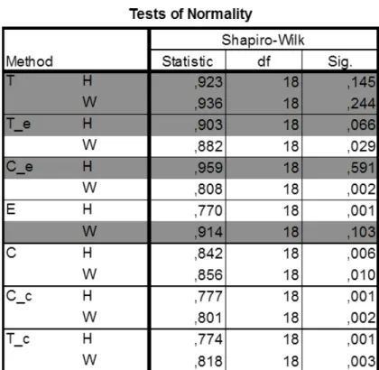
5.4 Test of normality, rows in gray indicates normally distributed vari-ables and the whites are not. . . 50
5.5 Mann-Whitney U Test for non-parametric variables . . . 51
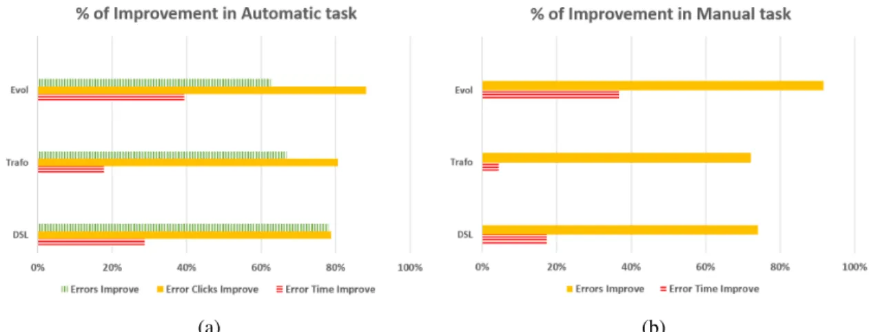
5.6 T-test for normally distributed variables . . . 52 5.7 Percentage of Improvements in time, number of clicks and errors. 54
5.8 Improvements in number of clicks, errors and time with respect to the complexity of an activity in a workflow for group A. . . 55 5.9 Improvements in number of clicks, errors and time with respect to
the complexity of an activity in a workflow for group B. . . 57 5.10 Effect size threshold showing Cohen’s D value . . . 58 6.1 New metamodel of workflows for modeling tools . . . 63 6.2 Workflow of the transformation example with dependencies. . . . 63 6.3 Workflow to create a DSL using dependencies. . . 64 VI.1 Step 1 to create a DSL in AToMPM . . . xlii VI.2 Step 2 to create a DSL in AToMPM . . . xlii VI.3 Step 3 to create a DSL in AToMPM . . . xliii VI.4 Step 4 to create a DSL in AToMPM . . . xliii VI.5 Step 5 to create a DSL in AToMPM . . . xliv VI.6 Step 6 to create a DSL in AToMPM . . . xliv VI.7 Step 8 to create a DSL in AToMPM . . . xlv VI.8 Step 9 to create a DSL in AToMPM . . . xlv VI.9 Step 10 to create a DSL in AToMPM . . . xlvi VI.10 Step 11 to create a DSL in AToMPM . . . xlvi VI.11 Step 12 to create a DSL in AToMPM . . . xlvii VI.12 Step 13 to create a DSL in AToMPM . . . xlvii VI.13 Step 14 to create a DSL in AToMPM . . . xlviii VI.14 Step 16 to create a DSL in AToMPM . . . xlviii VI.15 Step 17 to create a DSL in AToMPM . . . xlix VI.16 Step 18 to create a DSL in AToMPM . . . xlix VI.17 Step 1 to create a DSL in EMFText . . . li
VI.18 Step 2 to create a DSL in EMFText . . . li VI.19 Step 3 to create a DSL in EMFText . . . lii VI.20 Step 4 to create a DSL in EMFText . . . lii VI.21 Step 5 to create a DSL in EMFText . . . liii VI.22 Step 6 to create a DSL in EMFText . . . liii VI.23 Step 7 to create a DSL in EMFText . . . liv VI.24 Step 8 to create a DSL in EMFText . . . liv VI.25 Step 9 to create a DSL in EMFText . . . lv VI.26 Step 10 to create a DSL in EMFText . . . lv VI.27 Step 11 to create a DSL in EMFText . . . lvi VI.28 Step 12 to create a DSL in EMFText . . . lvi VI.29 Step 13 to create a DSL in EMFText . . . lvii VI.30 Step 14 to create a DSL in EMFText . . . lvii VI.31 Step 15 to create a DSL in EMFText . . . lviii
LIST OF APPENDICES
Appendix I: Tutorial on Using Workflows in AToMPM . . . xv
Appendix II: User Study Directives . . . xx
Appendix III: PostSurvey . . . xxxi
Appendix IV: Summary of the Results of the User Study . . . .xxxvi
Appendix V: Summary results Manual Task . . . .xxxix
I would like to dedicate this thesis to many people that were beside me throughout this exciting journey. To my wife, for her endless love, support and encouragement. To my son, who has been a source of inspiration. You have made me stronger, better and more playful than I could have ever imagined. To my parents, thank you for your tenderness, devotion and sacrifice.
ACKNOWLEDGMENTS
I would like to express my sincere gratitude to my advisor Prof.Eugene Syriani for the continuous support of my study and research, for his patience, motivation, enthusi-asm, and immense knowledge.
I thank my fellow labmates in GEODES Group, for the stimulating discussions and for all the fun we have had in the last two years.
Last but not the least, I would like to thank my family: my wife, my son and my parents, for supporting me spiritually throughout my life.
CHAPTER 1
INTRODUCTION
1.1 Context
Software engineering aims to create software tools that allow people to solve particu-lar problems in an easy and efficient way. To this end, once the solution to these problems is found, the following step is to optimize this solution. One particular optimization is to increase productivity during software development.
Model-Driven Engineering (MDE) is a software development approach that pro-motes automation dealing with domain-specific concepts that abstract away code. [48]. MDE technologies combine domain specific languages (DSL), transformation engines and code generators to produce various software artifacts. Although some studies report success stories of MDE [58], some of the less satisfactory results include the presence of several language workbenches [13]. These are Integrated Development Environments (IDE) to implement DSL, design, transform and verify models. MDE tools and lan-guage workbenches, such as AToMPM [56], EMFText [51], GME [30] and MetaEdit+ [22], provide many functionalities, such as DSL creation, model editing, or model trans-formations development and execution. Although based on common foundational prin-ciples, the process for performing these tasks differs greatly depending on the tool used. Each of these tools defines its own development and usage process, which is a burden on the user who needs to adapt himself to every tool. To be successful, MDE needs tools that are not only well adapted to the tasks to perform, but also tools that increase the productivity of modelers in their day-to-day activities.
1.2 Problem Statement and Thesis Proposition
All activities and tasks in modeling tools require context-dependent decisions leading to an excessive amount of user interactions with the user interface of the MDE tool. The processes to follow are complex for all users, whether they are language engineers (i.e., MDE savvy) or domain-specific modelers (i.e., end-users). They require heavy mental loads and tasks that are error-prone. In the end, users are spending more time on development than necessary. It is therefore mandatory to try to automate MDE tasks and processes as much as possible; thus, decreasing the accidental complexity of the tools used to let the user focus on the essential complexities of the domain problem.
To solve this issue, tools can implement automated workflows for each MDE activity that involves a complex process or repetitive tasks. Many of the tools already partially support this with the help of wizards [51] or scripts [38]. However, even these wizards become quite complex offering too many options that the user has to manually input each time he wants to repeat an activity, as in Eclipse based tools. There are also several languages to define processes, such as SPEM [41], but do not support their execution (or enactment) natively. Other executable process languages like BPEL [40] are too generic for the tasks we want to achieve in modeling tools. Workflow languages, such as UML activity diagrams, can be enacted [52], but the execution relies on programming individual actions which hampers porting a process from one tool to another.
Therefore, our proposal is to define an executable workflow that fits exactly the pur-pose of designing workflows for common tasks in MDE tools. Tasks encompass simple operations, such as opening, closing or saving models, and more complex tasks, such as generating the artifacts of a DSL. We noted that several tasks occur in different work-flows, especially common operations e.g. open and close. Therefore we opted for a reuse mechanism, where the user defines workflows that can be parameterized at
run-MDE paradigm, the execution of workflows is entirely modeled through model trans-formation. Ultimately, users spend less time performing the activity by focusing on essential model management tasks rather than wasting time interacting with the tool.
1.3 Contributions
The goal of this thesis is to improve the productivity of modelers using MDE tools by automating repetitive activities. The contributions of this thesis are the following:
1. A language to design and execute workflows that automate common MDE tasks. 2. An empirical analysis of the minimal effort required to perform activities with
workflows.
3. An empirical evaluation with real human users thats shows that mechanical efforts are reduced and fewer errors occur when using workflows.
1.4 Outline
This thesis is organized as follows. In Chapter 2, we present relevant information and related work. In Chapter 3, we describe details of our solution and discuss about how we solved challenges faced. Furthermore, we report on the implementation of our approach in AToMPM in a idealistic context. In Chapter 4,we analyze the impact our approach has on improving the user productivity in AToMPM. In Chapter 5, we perform an empirical user study to evaluate the improvement in productivity for real users. In Chapter 6, we improve the workflow language to further automate workflow design and execution. Finally, we conclude in Chapter 7.
CHAPTER 2
STATE OF THE ART
2.1 Model-Driven Engineering
MDE is a software development paradigm that enables to generate software tools, by systematically modeling and transforming models [15]. A model is an abstraction of a real system. Models play on crucial role as they provide information about the structure and behavior of software artifacts.
2.1.1 Modeling
Modeling is a fundamental concept in software engineering and even more in soft-ware development. Modern computer systems have reached a complexity that requires us to analyze them at different levels of abstraction. This is where model-based method-ologies and solutions ensure an adequate solution. However, diversity in the design pro-cess requires several formalisms designed for specific tasks. Intelligent design involves different models of different levels of abstraction which, when combined, maximize the knowledge we have of a system [33]. The future of engineering and software develop-ment emphasizes the use of models and the importance of design and impledevelop-mentation, including code generation or model transformation [39].
2.1.2 Domain-specific languages
MDE aims to reduce the gap between problem and software implementation domains through the use of technologies that support transformation of problem level abstractions to software level implementations [15]. In order to achieve this, models describe com-plex systems at multiple levels of abstraction and MDE has mechanisms to transform
models into running systems. These techniques shield stakeholders from the complex-ities of underlying implementation technologies. Within MDE, domain-specific model-ing focuses on creatmodel-ing models that leverage specific abstractions to a particular domain, as opposed to abstractions in lower level programming languages [23]. Thus, stakehold-ers can use DSLs to model their problems using abstractions from their own domains of expertise. A DSL is a modeling language tailored to the needs and habits of specific domain experts using notations and concepts they are familiar with.
A DSL is composed of three elements: abstract syntax, concrete syntax and seman-tics [37]. The abstract syntax defines the main concepts of the language, their relation-ships and constraints. The concrete syntax defines the language notation to represent and render models, which can be textual or graphical. The semantics of a DSL gives meaning to domain-specific models often by means of model transformation.
2.1.3 Metamodeling
A key element of the abstract syntax is the metamodel of the DSL [26]. It defines types, relations and static semantics of the language. To be well-formed, a model con-forms to its metamodel that specifies its permissible syntax. A metamodel is very often represented using UML class diagrams notation [42]. Classes represent the entities of the language. They can contain attributes to retain relevant characteristics of the class. Classes can be related by associations, composition, or specialization relations. Thus pragmatically, a model is an object model instance of the class diagram of the meta-model. As such, models are made of objects, attribute values and links, respectively instantiating classes, attributes and associations from the metamodel.
2.1.4 Deep metamodeling
Standard MDE approaches propose an instantiation mechanism that works as fol-lows: when a model element is instantiated from an metamodel element, the attributes and associations for the metamodel element becomes slots and links of the model el-ement and for this reason, they are not available for further instantiation. If an model element wants to have attributes or associations, these have to be defined explicitly or by specialization[5]. This is a know problem with strict 2-level metamodeling.
One solution is to apply techniques from deep metamodeling [28], and in particu-lar, the approach defining metamodels with potency. The potency of a model element is a number that defines the depth to which a model element can be instantiated. An attribute with potency 0 is a slot holding a value that must be set and can not be further instantiated, attribute with potency 1 must be instantiated at the next meta-level (default in 2-level metamodel-model relationship), and an attribute with potency 2 will be passed along at the instance level as an attribute and will only be assigned a value after two instantiations. There are software tools like Melanee [4] or Metadepth [10] that support deep metamodeling with potency.
2.1.5 Model transformation
In MDE, models can be manipulated using model transformation. It is used for code generation, model validation, model refactoring, translation mappings to produce mod-els, and execution via simulation of models in a systematic way. There are over 20 uses in the model transformation intents catalog [31]. Model transformation is defined at the level of the metamodels but executed at the model level. In general, this operation uses a source model as input and produces a target model as output, where each model con-forms to its respective meta-model. Model transformation literature considers a broad range of software development artifacts as potential transformation subjects [9].
A model transformation is made up of patterns, transformation units, and schedul-ing. Patterns specify the locations in the model where a rule is applied. The precondi-tion pattern must be found in the input model. A left-hand side (LHS) pattern contains those preconditions that must be met before applying the rule. To inhibit its application negative application conditions (NAC) can be used. Furthermore, precondition pattern elements may have specific constraints over their attributes. The postcondition pattern must be found in the output model after the rule is applied. A right-hand side (RHS) pattern contains those postconditions, and actions to be performed on attributes of its pattern elements.
Transformation units complement the rules by adding expressiveness to vary how a rule is applied on a model: e.g., applied once on a single match of the precondition pattern or applied as long as a match is found. Scheduling represents how the rules are executed. Scheduling can be achieved by explicit control structures or can be implicit due to causality dependencies between rules. Typical control structures include sequenc-ing, looping and branching of rules. For example, the model transformation language MoTif [55] offers several transformation units, called rule blocks. An ARule applies a rule on the first match it finds. An FRule applies the rule on all matches found simulata-neously. An SRule applies a rule recursively as long as a match is found. In MoTif, rule blocks are scheduled depending on the outcome of the rule, whether it was applied or not. This rule-based graph transformation language is espcially well-suited for defining simulations of a DSL and executing models [55].
2.1.6 Tools
Language workbenches are IDEs for engineering modeling languages, to implement DSL, design, transform, execute and verify models. Two of these tools are described below.
2.1.6.1 AToMPM
AToMPM [56] is an open-source framework for designing DSL environments, per-forming model transformations, as well as manipulating and managing models. It is a research framework from which one can generate domain-specific modeling web-based tools that run on the cloud. AToMPM uses the most appropriate formalisms and pro-cesses, being completely modeled by itself.
To create a DSL in AToMPM [6], the language designer has to load the class diagram formalism and graphically build the metamodel. He generates the abstract syntax of the DSL from that metamodel by loading the compiler toolbar. Then he has to load the concrete syntax formalism and assign a concrete syntax to each individual class and association from the metamodel by drawing icons and relations. He then generates the domain-specific modeling environment by loading the compiler toolbar. Finally, by using the concrete syntax created, the user can define a new model.
2.1.6.2 EMFText
EMFText [12] enables developers to define textual DSLs. Metamodels are described in Ecore, being implemented in the Eclipse Modeling Framework (EMF). To create a DSL in EMFText the language designer first creates a new project by specifying the project settings in the wizard dialog. He then creates an Ecore diagram file and graph-ically builds the metamodel. He then needs to create a generator model from the meta-model file. To define the concrete syntax, he creates a file specifying the textual grammar. Once completed, he executes the generators to create the domain-specific environment that needs to be launched as a separate Eclipse instance initiated from the generated Java code. Appendix VI has in detail the steps to create a DSL in AToMPM and EMFText.
The are important differences between these two tools, AToMPM can create graphi-cal DSL while EMFtext supports textual DSL. The concrete syntax in EMFtext is
repre-Figure 2.1 – AToMPM user interface showing a domain-specific model
sented through a grammar, while in ATOMPM is a set of icons and graphs.
Observing the process of DSL’s creation in both tools, we note that modelers have to know all the steps and perform many tasks and user interactions because the processes to follow are complex for all users, whether they are language engineers or domain-specific modelers, since they require heavy mental loads and tasks that are error-prone. There-fore, it is necessary to automate parts of the process to improve the modeling process.
2.2 User Errors in Tools with Graphical Interaction
Many of MDE activities such as DSL creation, model editing, or model transfor-mations involve repetitive tasks and a lot of user interactions with the user interface of the MDE tool. These are non-trivial activities. They involve long sequences of tasks, often repetitive tasks. Additionally, they require context-dependent decisions leading to a lot of user interactions with the user interface of the MDE tool. In the end, users are spending more time on development than necessary.
Type of errors
As [27] defines, a system works fine when his functionalities do what they must do. A failure, is an event that occurs when the functionalities deviates from proper functioning. A system fails either because it does not comply with the functional specification, or because this specification did not adequately describe the system function. It is an error. A good classification for the types of errors in Graphical User Interface (GUI) is found in [29], if the user makes an unnecessary action in performing the current task this is, in most cases, an error. However, the user may have wanted to go backwards in the interaction to a previous step. Another common type of error is an action performed belonging to the task, but the user has failed to do some necessary actions before. An error could also arise if the user inputs something to the program that is not correct.
Based on the above, the following four categories or of errors types were created:
Typographic error
A typographical error occurs when the user enters erroneous information into the system using the keyboard . For example entering the wrong name of a file or its exten-sion.
Functional error
A functional error is an error in which the user makes a mistake in the proper func-tioning of the system. For example, clicking on the wrong button when you want to perform a specific action. The desired action is not achieved since he clicked on another button.
Preconditional error
This mistake is made when a series of steps are needed to complete an action and one of these steps is omitted. This leads to not being able to perform the desired action.
Backtracking error
This error occurs when the user goes back to a previous step without completing a process.
2.3 Workflows
A workflow is the study of the operational aspects of a work activity: how tasks are structured, how they perform, how they are synchronized, how information flows to support the tasks and how monitoring is done to compliance tasks. Workflows have
been used to support various types of business processes [18]. The workflow patterns initiative was established aiming to delineate the fundamental requirements that arise during business process modeling [47].
The Basic Control Flow Patterns captures elementary aspects of process control. The following briefly explains each one.
2.3.1 Sequence
The sequence pattern serves as the fundamental building block for workflows. It is used to construct a series of consecutive tasks which execute in turn one after the other. Two tasks form part of a sequence if there is a control-flow edge from one of them to the next which has no guards or conditions associated with it.
2.3.2 Parallel split
The parallel split pattern allows a single thread of execution to be split into two or more branches that can execute tasks concurrently. These branches may or may not be resynchronized in the future.
2.3.3 Synchronization
Synchronization provides means of reconverting the execution threads of two or more parallel branches into a single one. In general, these branches are created using the parallel split construct earlier in the process model. The thread of control is passed to the task immediately following the synchronizer once all of the incoming branches have completed.
2.3.4 Exclusive choice
The exclusive choice pattern allows the thread of control to be directed to a specific (subsequent) task depending on the outcome of a preceding task, the values of elements of specific data elements in the process, the results of an expression evaluation or some other form of programmatic selection mechanism. The routing decision is made dynam-ically allowing it to be deferred to the latest possible moment at runtime.
2.3.5 Simple merge
The simple merge pattern provides a mean of merging two or more distinct branches without synchronizing them. As such, this presents the opportunity to simplify a process model by removing the need to explicitly replicate a sequence of tasks that is common to two or more branches. Instead, these branches can be joined with a simple merge construct and the common set of tasks needed only to be depicted once in the process model.
2.3.6 Arbitrary cycles
The ability to represent cycles in a process model that have more than one entry or exit point. It must be possible for individual entry and exit points to be associated with distinct branches.
2.3.7 Structured loop
There are two general forms of this pattern: the while loop which equates to the classic while...do and the repeat loop which equates to the repeat...until construct.
2.3.8 Transient trigger
Transient triggers are a common means of signaling that a predefined event has oc-curred and that an appropriate handling response should be undertaken.
2.3.9 Persistent trigger
The ability for a task to be triggered by a signal from another part of the process or from the external environment. These triggers are persistent in form and are retained by the process until they can be acted on by the receiving task
2.4 Existing Approaches to Automate User Activities
A lot of work can be found in the literature on workflow definition and enactment [35, 46, 60]. In [19], the authors proposed a textual DSL for workflow definition that supports sequencing and iteration. It is not meant to be enacted, but serves as specifica-tion for subsequent code generators. Workflow enactment has been particularly applied in process modeling. Various techniques exist to service the execution of workflows, such as distributing the execution on the cloud [2, 36]. However, none of these ap-proaches models workflow enactment explicitly as we did using model transformation. We propose a model transformation as a novel workaround for tools that do not support deep instantiation of Metamodels. An alternative is to define Metamodels following the Type-Object pattern [21] where both types and instances are explicitly modeled in the Metamodel. This is similar to the notion of clabject [3] which generalizes this approach. Existing works use transformations chains, but not workflows. Others approaches execute wizards to automate repetitive tasks, but none combine workflow definition, workflow execution and MDE techniques. This makes our approach unique. With these approaches, no one reported an improvement performing task.
2.4.1 The FTG+PM language
From an implementation point of view, the closest work to ours automates transfor-mation chains in AToMPM [32]. The FTG+PM language is defined using two sub-languages: the Formalism Transformation Graph (FTG) language and a Process Model (PM) language. They developed a formalism transformation graph (FTG) that specifies a megamodel indicating the transformations between languages and a process model (PM) that specifies the control and data flow to schedule the order of execution of model transformations. The building blocks of the FTG are formalisms (nodes in the graph) and transformations (edges in the graph). The FTG describes the different languages that can be used at each stage of model development. The transformations model devel-opment activities, and the control flow and data flow between each transformation action are explicitly modeled in the PM. The execution of an FTG+PM instance is modeled as a higher-order transformation that converts the FTG+PM model into a model transfor-mation instance. The transfortransfor-mations defined as activities in the PM are all modeled as rule-based graph transformations using AToMPM’s transformation language. Whereas our approach executes workflows by simulation. The authors also distinguish automatic actions from manual ones, but the latter are not modeled in the transformation.
2.4.2 Wires
Wires [44] is a graphical executable language for orchestrating ATL transformations. Wires assumes a data-flow process, in which a set of input models (conforming to their corresponding metamodels) are processed by a chain of ATL transformations until a set of output models is produced. Similarly to FTG+PM, Wire supports the specification and execution of model transformation workflows. Basically, Wires provides mecha-nisms to create model transformations chains. The chain is composed of transformations, which act as processing nodes. Parameters represent the consumed and produced data
by transformations. Transformations are wired together by directed connectors (Wires) that indicate how the outputs of the transformations are linked to the inputs of the next ones.
2.4.3 Epsilon wizard language
The Epsilon Wizard Language (EWL) [24] provides tailored and effective support for defining and executing update transformations on models of diverse metamodels. Severals tools provide built-in transformations (wizards) for automating common repeti-tive tasks. However, according to the architecture of the designed system and the specific problem domain, additional repetitive tasks typically appear, which cannot be addressed by the preconceived built-in wizards of a modeling tool. EWL helps to create wizards for those specific needs.
In our approach, activities essentially encapsulate model management tasks. The Epsilon language suite [25] can be used to perform model management tasks such as CRUD operations, transformations, comparisons, merging, validation, refactoring, evo-lution, and code generation. To combine and integrate these different tasks into work-flows, the user defines Ant Scripts.
In our approach, users define workflows in a DSL specific to the features the MDE tool provides. As such, it reduces accidental complexity imposed by Ant and is accessi-ble to a broader set of users that do not know Ant.
EWL whose purpose is to refactor, refine, and update models allows users to de-fine wizards that serve as encapsulation of EOL scripts, the action language in Epsilon. Wizards are similar to activities in our case. EWL provide feedback that can drive the execution of a model management operation using a context-independent user input. It is a command line user input interface.
Their approach has a more fine-grained Wizard Selection Process, since a wizard can have a guard that must be satisfied in order to execute it. Nevertheless, EWL does not support the explicit modeling of manual tasks. EWL is especially designed for refactor-ing models automatically. These model refactorrefactor-ings are applied on model elements that are explicitly selected by the user. Typical supported refactoring patterns include adding the stereotypes, attributes and operations. EWL has constructs specifically to refactor model elements. In our approach, workflows rely on a model transformation to express the modification to the model. Therefore the user only needs to specify the model, and not individual model elements.
CHAPTER 3
DESIGN OF A REUSABLE WORKFLOW LANGUAGE
We propose an MDE-based solution where the user defines workflows that can be parametrized at run-time and executed. In this chapter, we describe a DSL that is adapt-able to a specific modeling tool. We also describe the general process of how to design reusable workflows to semi-automate MDE activities. Furthermore, we discuss how to enact workflows using model transformation.
3.1 Language for Semi-Automated Workflows
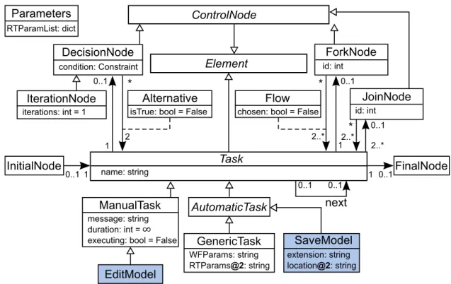
We model the DSL for defining activities that can be performed in MDE tools. An activity is composed of tasks, to define concrete actions to be performed, and control nodes, to define the flow of tasks. The metamodel in Figure 3.1 resembles that of a sim-plification of UML activity diagrams since, semantically, an instance of this metamodel is to be interpreted similarly to the control flow in UML activity diagrams. Additional well-formedness constraints are not depicted in the figure e.g., a cycle between tasks must involve an iteration node, there must be exactly one initial and one final node.
There are different kinds of tasks in an MDE tool. As for any modern software, there are tasks specific to the user interface, such as opening, closing, and saving models or windows. There are also tasks that are specific to models, such as editing (CRUD operations) models, constraints, or transformations. There are also tasks that are spe-cific to the particular modeling tool used, such as loading or executing a transformation, generating code from a model, or synthesizing a domain-specific environment from a DSL. Furthermore, we want to automate user’s activities as much as possible, therefore most of the tasks are automatic: they do not require human interaction. For example,
AutomaticTask GenericTask WFParams: string RTParams@2: string extension: string location@2: string SaveModel EditModel InitialNode FinalNode DecisionNode
condition: Constraint id: int
IterationNode iterations: int = 1 ControlNode 0..1 0..1 0..1 0..1 0..1 0..1 2..* 2 * * * 2..* 1 1 1 ManualTask message: string duration: int = executing: bool = False
∞ 0..1 2..* Task name: string id: int JoinNode ForkNode Flow
chosen: bool = False
1
Element
RTParamList: dict
Parameters
Alternative
isTrue: bool = False
next
Figure 3.1 – Generic metamodel of workflows for modeling tools
loading a formalism to create a metamodel is (e.g., Ecore in EMF or Class Diagrams in AToMPM) is a task that can be automated, since the location of that formalism is known. Shaded classes in Figure 3.1 (SaveModel and EditModel) are examples of tasks that may vary from one MDE tool to another. Otherwise, this is a generic metamodel imple-mentable in any MDE tool.
Nevertheless, some tasks are hard, even impossible, to automate and thus must re-main manual. These are typically tasks specific to a particular model, such as deciding what new element to add in the model. A message is specified to guide the user during manual tasks. A maximum duration can also be specified to limit the time spent on a manual activity.
A workflow conforming to the metamodel starts from the initial node and terminates at the final node. Tasks can be sequenced one after the other. A decision node can be placed to provide alternative flows depending on a Boolean condition evaluated at
run-time. Repetitions are possible with an iteration node. The cycle ends when either the specified number of iterations is reached or a terminating condition is satisfied. Fork and join nodes provide non-determinism when the order of execution of tasks is not rel-evant. These correspond to the common basic control flow patterns for workflows [47]. Although not supported in our current implementation, tasks may be executed concur-rently, except if the concurrent tasks are manual.
3.2 Parameters
One issue that may slow down the development time of users using workflows, is that many tasks require parameters. For example, the task SaveModel requires the location of where to save the model (path and name) and the extension to be used. The extension is generally known from the context of the workflow. For example, a generic model ends with .ecore in EMF and .model in AToMPM, but a domain-specific model may have a specific extension in EMF. The designer of the workflow can thus set the value of this attribute at design-time. However, the location of the model is generally unknown to the workflow designer because it is a decision often left at the discretion of the domain user. We therefore distinguish between workflow parameters that are fixed for all executions of the workflows and run-time parameters that are specific to individual executions of the workflow.
3.3 Activities as Workflows
To set the values of run-time parameters, we need an intermediate model of work-flows that is an instance of the metamodel presented, but where some parameters are left for further assignment. As explained in [16], the commonly used technique of two-level metamodeling does not allow us to represent this need.
An attractive solution is to apply techniques from deep metamodeling [28], and in particular, the approach defining metamodels with potency. We assign a potency of 2 to attributes representing run-time parameters and a potency of 1 to those representing workflow parameters, as depicted in Figure 3.1. This way, the workflow designer only needs to create one workflow for saving models with the extension set to e.g., .model and the user can execute the workflow only caring of the location where to save the model and not bother what the right extension is. In this setup, an instance of the work-flow metamodel in Figure 3.1 is a workwork-flow. A workwork-flow is itself the metamodel of its instantiation at run-time. The enactment of a workflow therefore consists in providing the run-time parameters to a workflow and executing it. These definitions are consistent with what the Workflow Management Coalition specifies [59].
3.4 Workflow Enactment by Model Transformation
In this section, we describe how workflows are instantiated with run-time parameters and executed.
3.4.1 Deep instantiation
The issue with the above solution is that not many modeling frameworks(e.g., AToM-PM1and EMF) support deep metamodeling with potency like Metadepth or Melanee do. Therefore, we propose a workaround to enact workflows by emulating deep metamod-eling with potency for tools that do not natively support it. The solution is to add a Parametersclass to the metamodel that is instantiated once per workflow enactment. Its attributes are populated dynamically for the enactment. They consist of all the run-time parameters of every task in the workflow. The parameter object is used to generate
1. In [57], the authors proposed a deep metamodeling solution for the Modelverse of AToMPM, but no usable implementation was available at the time of writing this paper.
a wizard prompting for all run-time parameters needed in the tasks of a workflow. Once a workflow has been created by the workflow designer, a user can enact the workflow. He creates a parameter object to specify run-time parameters and executes the workflow. We have modeled the enactment of workflows by model transformation. Figure 3.2 depicts the transformation in MoTif [55], a rule-based graph transformation language in AToMPM. Rules are defined with a precondition pattern on the left and a post-condition pattern on the right. Constraints Const and actions Act on attributes are specified in Python. The transformation in Figure 3.2 populates all attribute fields of the parameter object (the icon with two gears) by visiting each task in the activity model. The attributes names and types are stored in a JSON format that is then used to render a wizard prompting for their corresponding values to the user. This is performed in a single FRule that makes sure that each task is visit exactly once. Note that the transformation uses a FRule to make sure that each task is visited exactly once, which is why no negative application condition is needed.
LoadRTParams
:
LoadRTParams
for a in PreNode(1).getAttrs(): if '@2' in a: PreNode(2).paramList.add( '{' PreNode(1) ':' a[:-2] '}')Task
1
2
Task
1
2
F
3.4.2 Execution
With all run-time parameters set, there are two ways to execute the workflow. One is to transform the workflow into a model transformation that gets executed, as done in [32]. In this case, a higher-order transformation takes as input the workflow and parameter object, generates a rule for each task, and schedules the rules according to the order of the tasks in the workflow. This is possible in MoTif since rules and scheduling are specified in separate models. Although this approach has the advantage to reuse built-in execution mechanisms from the MDE tool, a new transformation must be generated for each workflow and, in particular, if the designer makes changes to the workflow model.
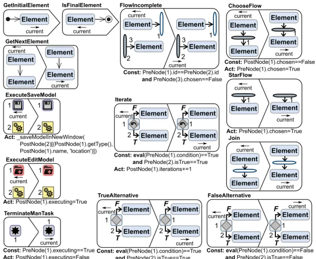
In this work, we have implemented an alternative solution: we define the opera-tional semantics of a workflow and execute it as a simulation. Figure 3.3 illustrates the overall structure of this transformation and Figure 3.4 depicts some of the rules. The process starts from the element (task or control node) marked with the initial node. The rule GetInitialElement is responsible for this and specifies only a precon-dition. The general idea is that then, each task to process each element in the order of the workflow by advancing the current pointer called pivot in MoTif, with the rule GetNextElement. The simulation ends when the final node is reached, satisfying the rule IsFinalElement. Executing an automatic task, such as save model depicted in rule ExecuteSaveModel, is performed by calling the corresponding API opera-tion of the MDE tool with the corresponding run-time parameters, . We assume that the MDE tool offers an API for interacting with it programmatically (e.g., Python API for AToMPM and Java API for EMF).
When a control node is the current element to process, we need to decide on which element is next to be processed. For a decision node, if the condition is true, then the next element along the true branch is selected. Otherwise, it is the next element along the false
: GetInitialElement ? : GetNextElement : IsFinalElement B B : EvalCtrlNode : ExecAutoTask : ExecManTask : TerminateManTask ? : EvalDecisionNode : EvalFlowNode : EvalCtrlNode : FalseAlternative : EvalDecisionNode : Iterate : TrueAlternative : EvalFlowNode : FlowIncomplete : ChooseFlow : Join :StarFlow
Figure 3.3 – Control structure of the transformation in MoTif that executes a workflow branch. This assignment is the same for iteration nodes, except that the iterations count is incremented as long as the condition is satisfied. In our implementation, the semantics of a fork is to choose non-deterministically one of the flows, execute all tasks in that flow in order, and then choose another flow. The rules in EvaluateFlowNode ensure this logic: when a join node is reached, we make sure that all flows outgoing from the corresponding fork are complete as expressed by rule FlowIncomplete.
This process runs autonomously as long as there are automatic tasks. However, man-ual tasks require interruption of the transformation in real-time so that the user can com-plete the task at hand and then resume the transformation. Automating such a process requires to be able to pause and resume the transformation from the rules being ex-ecuted. Although some transformation languages support real-time interruption [54], most do not. Therefore, as depicted in Figure 3.3, we extend the logic to handle manual
TerminateManTask Const: PreNode(1).executing==True Act: PostNode(1).executing=False current 1 1 GetInitialElement current Element ExecuteSaveModel Act: _saveModelInNewWindow( PostNode(2)[(PostNode(1).getType(), PostNode(1).name, 'location')]) current 1 2 1 2 ExecuteEditModel Act: PostNode(1).executing=True current 1 2 1 2 GetNextElement current current Element Element Element Element IsFinalElement current Element current Join current Element Element Element Element ChooseFlow Const: PostNode(1).chosen==False Act: PreNode(1).chosen=True current current 1 Element Element Element Element Iterate Const: eval(PreNode(1).condition)==True and PreNode(2).isTrue==True Act: PostNode(1).iterations+=1 current 1 2 Element Element 1 2 Element Element current F T F T FalseAlternative Const: eval(PreNode(1).condition)==False and PreNode(2).isTrue==False current 1 Element Element 1 2 Element Element current F T F T 2 TrueAlternative Const: eval(PreNode(1).condition)==True and PreNode(2).isTrue==True current 1 2 Element Element 1 2 Element Element current F T F T FlowIncomplete Const: PreNode(1).id==PreNode(2).id and PreNode(3).chosen==False 2 3 Element current 1 Element 2 3 Element current 1 Element StarFlow Act: PreNode(1).chosen=True current current 1 Element Element 1 1
tasks separately. If the next task to execute is manual, the corresponding rule simply flags the task as executing, as rule ExecuteEditModel shows, and the transforma-tion terminates. The user notifies the MDE tool that his manual task is complete by restarting the transformation. Consequently, the transformation executes the first rule TerminateManTaskwhich resumes the execution from the task that was last marked as executing. The executing attribute for manual tasks allows the workflow model to keep track of the last manual task executed after the transformation is stopped.
3.5 Extensions and Exceptions
The approach presented here is evolution safe. MDE tools evolve with new features added. If a new feature is available via the API and is needed in an workflow, then there are only two steps the designer is required to perform to support that feature. He shall add a new sub-class of automatic or manual task in the metamodel of Figure 3.1 and add a rule under ExecAutoTask or ExecManTask in Figure 3.3 that calls the appropriate API function to perform the operation. ExecAutoTask (respectively ExecManTask) is a BRule that contains all the rules to execute automatic (respectively manual) tasks. BRules execute at most one of their inner rules unless none of them are applicable. The modularity of this design reduces significantly the effort of workflow designers who wish to provide additional tasks available via new features of the MDE tool.
Although it is common to explicitly model exceptional cases in workflows [45, 53], we have decided not to do that at the workflow model level. Exceptions can only occur if a task execution fails because the user is constrained to do exactly what the workflow allows as next action. In this version of our implementation, if an exception occurs, the workflow execution stops at the failing task in the workflow, as depicted by the circled crosses in Figure 3.3. The user must then manually recover from the error and restart the execution of the workflow. Nevertheless, run-time parameters are retained.
3.6 Implementation in AToMPM
We implemented a prototype in the MDE tool AToMPM [56], since it offers a graph-ical concrete syntax for DSLs, which is best suited for workflow languages, and a back-door API to programmatically interact with the tool in headless mode. Nevertheless, our approach can be implemented in any MDE tool as long as it offers an accessible API to perform operations that their user interface allows to. We implemented the workflow DSL following the metamodel in Figure 3.1. Figure 3.5 shows the graphical representa-tion used for each task, each control node, and parameter object.
We analyzed several processes and noted the user interactions needed to perform each task, e.g., creation of DSL. We had to decide on what level of granularity we want to present tasks. One option is to go to the level of mouse movements (graphically mov-ing objects), clicks (selections), and keystrokes (textual editmov-ing). Although this would enable us to model nearly any user interaction AToMPM allows for, this would make the workflows very verbose and complex for designers. We therefore opted for tasks to represent core functionalities instead. Subsequently, the most common tasks we noted are opening models, loading toolbars and formalisms, saving models, generating con-crete and abstract syntax of DSLs, as listed in Figure 3.5. All these operations can be automated, since they require a location as run-time parameter. SaveModel also has
GeneratePMM VerifyAS OpenTransformation ForkNode JoinNode FinalNode InitialNode DecisionNode Control nodes LoadToolbar Automatic tasks Workflow execution LoadParameters ExecuteWorkflow Manual tasks ManualTask EditModel CompleteManual OpenModel SaveModel GenerateAS GenerateCS
Parameters
IterationNode ExecuteTransformation RefactorModel
a workflow parameter for the extension of the model file. Additionally, a task to edit models is needed, but cannot be automated since it is up to the user to create or edit the model.
3.7 Process
Our prototype is to be used as follows:
1. The designer defines workflows by creating instances of the workflow DSL.
2. A user (a language engineer in this example) then selects which workflow he desires to enact; in this case, a DSL workflow.
3. To set the run-time parameters, he pushes the LoadParameters button. This cates an instance of the parameter object and pops up a dialog prompting for all re-quired parameters, following the transformation from Figure 3.2. This is shown in Figure 3.6
4. The user push OK button as seen in Figure 3.7 .
5. Upon pushing ExecuteWorkflow button shown in Figure 3.8 , the simulation (presented in Figure 3.3) executes the workflow autonomously. When a manual task is reached, a new AToMPM window is opened with all necessary toolbars preloaded. A message describing the manual task to perform is displayed to the user and the simulation stops.
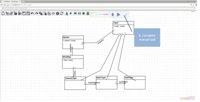
6. After the user completes the task, he pushes the CompleteManual button. Then, the window closes and the simulation restarts. This is shown in Figure 3.9
3.8 Example Workflow for Creating a DSL
1
2
3 1
2
Figure 3.6 – Step 1 to create a DSL using workflows. Load Parameters
Figure 3.8 – Step 3 to create a DSL using workflows. Enact a workflow
parameter is already predefined with the class diagram toolbar, since this is the stan-dard formalism with which one creates a metamodel in AToMPM. The following task is EditModel. In this manual task, the user creates the metamodel of the DSL using class diagrams.
Once this is complete, the workflow restarts executing from that task and proceeds with SaveModel. This task requires a run-time parameter to specify the location of where the metamodel is saved. The user sets the value in the popup dialog wizard.
Now that the metamodel is created, a fork node proposes two flows: one for creating the concrete syntax of the DSL and one to generate the abstract syntax from the meta-model. Recall that the simulation chooses one flow and then the other in no specific or-der. Suppose the former flow is chosen. Then, a LoadToolbar task is executed to load the concrete syntax toolbar, the standard formalism in AToMPM. This is followed by an EditModelso the user can manually create the shapes of each element of the meta-model. Once this is complete, the workflow restarts and proceeds with a SaveModel task. Recall that the location is a run-time parameter to save the concrete syntax model with a predefined extension. In the popup dialog, we distinguish between different task with their type. The following task in this flow is GenerateCS. It takes as run-time parameter the location of where the generated artifact must be output. Specifically, the name used will be also the name of the toolbar that will be used to create a model with this DSL.
When the join node is reached, the simulation notices that the second flow was not executed yet. Therefore the next task to be executed is GenerateAS.
When the join node is reached again, this time all flows were executed and proceeds with the final task LoadToolbar. The simulation ends on a new window open with the new DSL loaded, ready for the user to create his domain-specific model.
CHAPTER 4
ANALYSIS OF THE IMPROVEMENT WHEN USING WORKFLOWS
We perform an evaluation of the impact our approach has on improving the user productivity in AToMPM. However, this study does not rely on users and the results are independent from user performance. To do so, we focus on the mechanical efforts user would need to complete an activity. This corresponds to mouse operations for a graphical MDE tools like AToMPM. We extrapolate the cognitive efforts of the user to be the delays between individual mechanical operations.
4.1 Research Question
The goal of the experiment is to determine whether the productivity of the user is increased when performing complex or repetitive tasks. Thus, our research question is “is the time for mechanical and cognitive efforts of the user reduced when automating activities with workflows?” Therefore, we conduct the experiment to verify that these efforts are reduced when using our approach versus when not.
4.2 Metrics
The total time T spent by a user to perform one activity is one way to quantify the effort the user produces. T is mainly made up of the mechanical time Tm (hand
movements) and cognitive effort time Tt (thinking time) of the user, thus T = Tm+ Tt,
assuming there are no interruptions or distractions.
Since AToMPM only presents a web-based graphical user interface and most inter-actions are performed with a mouse, we can apply Fitts Law [34] to measure the time of mouse movements t = a + b × log (1 + D/S). D is the distance from a given cursor
position to the position of a widget to reach (e.g., button, text field) and S is the small-est value of the width or height of the widget. We denote TFL as the sum of all the tFL
for each useful mouse movement to perform one activity. TFL is calculated using the
formula in
Another useful metric we noted for the mechanical effort is the number of clicks C needed to complete the activity. Relying on empirical data from an online bench-mark [17], the average time to click reactively is 258 milliseconds. Thus we denote Tc= 258 × c the time spent clicking during an activity.
Therefore a rough estimate of the time spent on mouse actions in an activity is Tm=
TFL+ Tcfor every straight line distance D between two clicks and the size S of the widget
at every even click.
Delays between mechanical actions is a rough estimate of the time the user spent thinking during the activity. Hence, we deduce the thinking time Tt= T − Tm.
Finally, we measure the complexity K of an activity is the minimum numbers of clicks it requires the user to perform. In this case, the minimum number of clicks re-quired to complete an activity equals the number of clicks C, since this study was de-signed in a scenario without errors where the number of clicks an activity was optimized. Hence K = C.
These metrics are far from accurate, but serve at least as a preliminary evaluation of our approach to discard the null hypothesis: Tm, Tc and Tt are smaller for performing an
MDE activity in AToMPM using workflows than without workflows.
4.3 Experimental Setup
We performed all experiments on a 15.6” laptop monitor with a resolution of 1920 × 1080 pixels. The machine was an ArchLinux virtual machine using 2 cores and 4GB of RAM, running on Windows 10 quad-core computer at 2.4 GHz with 16 GB of RAM.
Given this performance, we neglected the computation time of AToMPM triggered by each click. To keep a fair comparison, the experiments using the workflow did not take into account the mouse activity and time spent during manual tasks. This is the time after the simulation terminates and before the notification from the CompleteManual button is received. The software used to collect data are: Page Ruler [43] and Perfect Screen Ruler [49] to measure several distances and Auto Mouse Clicker to record mouse movements and clicks.
4.4 Data Collection
To calculate T using Fitts law, the coefficients a and b must be determined em-pirically. For that, we recorded the straight line distances between meaningful clicks (e.g., center of canvas to toolbar button) as well as different sizes of clickable elements (e.g., model elements on the canvas) in AToMPM. We recorded 12 distances ranging from 79 to 1027 pixels and 5 sizes ranging from 20 to 305 pixels. We then placed on an empty screen a point and a rectangle of sizes and at distances that correspond to these measurements. We measured the time it took to click on the initial point and move the cursor as fast as possible to click inside the opposite rectangle. This data collection was performed by the first author who is an expert in AToMPM. We repeated each of the 57 cases 20 times (excluding those where D ≤ S). The maximum variation in the same case was less than 9%. We determined by regression analysis the values a = 166.75 and b= 155.93 with correlation R2= .9106 with a median and average margin of error of 8%.
These results lead us to the following equation that allows us to predict the mechani-cal time for a given screen size and distance of objects and AToMPM. The time of mouse movement for AToMPM is
TFL= 166.75 + 155.93 × log2(1 + D/S) (4.1)
In our prototype, we implemented the five most common tasks in AToMPM shown in Figure 3.5. There is an infinite number of possible combinations of these tasks because tasks can be repeated and the order matters. Therefore, we reduced the number of cases to only meaningful combinations of tasks in AToMPM. We identified 4 meaningful for activities with one task (compiling the concrete syntax requires a model to be opened), 9 for activities with two tasks (e.g., open then save model), 13 for activities with three tasks, 4 for activities with four tasks, 5 for activities with five tasks, 3 for activities with six tasks, and 3 for activities with seven tasks. Hence we ran our experiments on 38 distinct activities varying up to seven automatic tasks.
The most complex activity we evaluated is for the creation of a DSL in AToMPM modeled with the workflow in Figure 6.3, consisting of seven automatic tasks. The workflow starts by loading the Class Diagram formalism. It lets the user manually create the appropriate class diagram model to define the metamodel. When the user completes that task, the metamodel is saved (location provided at run-time) and the abstract syntax is generated. Then the ConcreteSyntax formalism is loaded and the user creates the shapes for links and icons. When the user completes that task, the concrete syntax model is saved (name provided at run-time) and the GenerateCS task generates the code for the new DSL environment. Finally, the new formalism is loaded in a new window showing the new generated DSL environment to the user. Note that in this situation, the first LoadToolbar object does not require a run-time parameter, but a workflow parameter for the location of the Class Diagram formalism. We therefore suggest to create two classes in the metamodel for the same task when we want to give the option to set either run-time or workflow parameters depending on the context.
4.5 Results
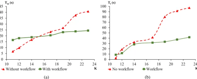
The two plots in Figure 4.1 report the time performances for each case. We aggre-gated the times by the number of tasks because there was very few variability between activities with the same number of tasks: the highest coefficient of variability 20% was obtained for activities with three tasks since this was the most populous set, while all the others remained under 5%. Both plots confirm that the use of workflows does reduce the time to perform the activity, as the complexity of the activity increases.
The results obtained correspond to what one would expect when adding automation in a development process. The mechanical effort is greater when using workflows for simple activities that have up to three tasks. However, after that point, the mechanical effort remains almost identical as the number of tasks increases. This behavior, depicted in Figure 4.1(a), is due to the overhead to open the appropriate workflow and set all run-time parameters. The reason why Tmplateaus after K = 17 is that the only mechanical
effort needed is to specify additional run-time parameters. However, this is done by typ-ing the values with the keyboard which we haven’t taken into account in this experiment. When performing the experiments, we noted that the slowest task performed manually was for loading toolbars.
Figure 4.1(b) reports on the non-mechanical effort needed by the user to perform each activity. We note a trend similar to the mechanical effort. However, the flip point where less effort is needed when using workflows occurs as early as activities with more than one task. The cognitive effort increases linearly for activities with more than three tasks. An interesting result is that, when not using workflows, the cognitive effort is always greater than the mechanical effort for K > 11 and that gap keeps on increasing as there are more tasks. On the contrary, when using workflows, the mechanical effort is greater for activities with up to two tasks, but when the cognitive effort is greater for
(a) (b)
Figure 4.1 – Mechanical (a) and cognitive (b) efforts with respect to the number of tasks in a workflow
that most of the time was spent searching on the screen to select toolbars to load, even for an expert user who knows exactly their locations.
To complement this information, Table 4.I details each metric for the most complex activities we evaluated. It shows that, although using workflows improves all the metrics, the cognitive time is the most improved component.
We conclude that our hypothesis is verified and answer our research question: for the extent of the experiments we conducted, the time for mechanical and cognitive efforts of the user is reduced when automating activities with our approach by half.
T TFL Tc Tm Tt
No workflow 138 29 11 41 98
Workflow 66 18 6 24 42
Improvement 52% 38% 45% 41% 57%
Table 4.I – Time measurements in seconds and improvements when using workflows for K= 23 task complexity
4.6 Threats to Validity
There are several threats to the construct validity of this preliminary evaluation. First, the metrics we used are not sufficient to assess the complete mechanical effort. Keystrokes can also be taken into account since there is an effort needed to set the val-ues of run-time parameters. However, the length of the string of each depends on the file paths of the host machines and the operating system used. We discarded this met-ric for its lack of generalization. Further mechanical metmet-rics could be used such as eye movements, but we lacked the proper hardware to perform eye-tracking experiments. We further mitigated these threats by using Fitts Law to achieve an objective measure of time mouse movements. We measured cognitive effort by considering it as all non-mechanical effort, which is not a completely true statement. Otherwise, this would have required more fine grained measurements of brain activity. We also did not include the time and effort for manual tasks, which may have a negative influence on the results if they take longer than the automatic tasks. The data collection was performed by only one person, but this was only necessary to calculate t since all other metrics are obtained using Fitts Law, without needing to perform the activities. This threat only affects the absolute time, but does not affect the improvement ratio.
With respect to threats internal validity, the selection and configuration of the tools for time measurements has a weak influence on the results. We calibrated the parameters based on a pilot experiment and our experience. However, this should not strongly affect the time because we took care of configuring the tools in a way that corresponds to the empirical data from an online benchmark. We also preprocessed inconsistent times (e.g., clicks outside target) in order to eliminate false positives. Nevertheless, this only reduces the chances that we can answer our research question positively.
edge in MDE tools. Hence, the set of activities is not completely representative. The results of this study can only be generalized to the extent of AToMPM. Nevertheless, all five tasks we considered are part of the most common activities in the majority of MDE tools, such as EMF. We further mitigated this threat by including tasks with dif-ferent complexity (i.e., Open Model vs Compile Abstract Syntax) and focusing on their meaningful combinations.