HAL Id: hal-02190720
https://hal.archives-ouvertes.fr/hal-02190720
Submitted on 22 Jul 2019HAL is a multi-disciplinary open access archive for the deposit and dissemination of sci-entific research documents, whether they are pub-lished or not. The documents may come from teaching and research institutions in France or abroad, or from public or private research centers.
L’archive ouverte pluridisciplinaire HAL, est destinée au dépôt et à la diffusion de documents scientifiques de niveau recherche, publiés ou non, émanant des établissements d’enseignement et de recherche français ou étrangers, des laboratoires publics ou privés.
Swaminath Venkateswaran, Damien Chablat, Ramakrishnan Ramachandran
To cite this version:
Swaminath Venkateswaran, Damien Chablat, Ramakrishnan Ramachandran. Prototyping a piping inspection robot using a BeagleBone black board. 24éme Congrès Français de Mécanique, Aug 2019, Brest, France. �hal-02190720�
Prototyping a piping inspection robot using a
BeagleBone black board
Swaminath Venkateswaran
a, Damien Chablat
b, Ramakrishnan
Ramachandran
ca. Ecole Centrale de Nantes, Laboratoire des Sciences du Numérique de Nantes (LS2N), UMR CNRS 6004, 1 rue de la Noë, 44321 Nantes, France, [email protected]
b. CNRS, Laboratoire des Sciences du Numérique de Nantes (LS2N), UMR CNRS 6004, 1 rue de la Noë, 44321 Nantes, France, [email protected] c. Mechatronics Lab, Department of Design & Automation, School of Mechanical Engineering (SMEC) Vellore, Vellore Institute of Technology (VIT), Vellore, India, [email protected]
Résumé :
Dans le cadre d’un projet avec AREVA, un robot d’inspection de canalisation de 50 à 94 mm de diamètre a été développé. En utilisant des pattes, des moteurs à courant continu, des vis-écrous et des cartes électroniques, le robot imite la locomotion d’une chenille. Deux algorithmes peuvent être utilisés pour le contrôle de ce robot: le contrôle en position ou le contrôle en effort. Le premier est utilisé pour l’estimation de la position d’un robot lorsque l’environnement est connu mais nécessite des codeurs pour identifier la position des pattes. Dans le cas du contrôle en effort, l’algorithme permet au robot de se déplacer dans un environnement inconnu. En utilisant une carte électronique BeagleBone (BB) black, un algorithme de contrôle en effort est développé pour ce robot d’inspection. Comme le robot travaille à l’intérieur de tuyaux de diamètres inconnus, les sorties PWM de la BB black sont utilisées pour générer la tension nécessaire qui permettant le clampage du robot. En fixant ces seuils, la tension et le courant dans les moteurs peuvent être évalués pour détecter la fin des mouvements de clampage ou de repliement. Avec l’aide des ADC, la tension de sortie est affichée à l’utilisateur sur un ordinateur. Pour le bon fonctionnement du robot, les paramètres du moteur tels que la vitesse maximale, le sens de rotation et le courant nominal sont étalonnés au début des expériences. La tension de sortie et les courants consommés sont générés et tracés pour un cycle de locomotion du robot dans un tuyau droit de 74 mm de diamètre.
Abstract :
As a part of a project with AREVA, an inspection robot for 50-94 mm diameter range pipelines have been developed. By using leg mechanisms, DC motors, spindle drive, and control boards, the robot ac-complishes the locomotion of a caterpillar. Two algorithms can be classified for the control of this robot via Displacement control algorithm and Force control algorithm. The former deals with the estimation of the position of a robot inside a known environment and it requires sensors for identifying position as well as for initiation procedures. In the case of force control, the algorithm is highly suitable for a robot that moves inside an unknown or closed environment. Using a BeagleBone (BB) black board, the force control algorithm is developed for the inspection robot under study. As the robot works inside
pipelines of unknown diameters, the reconfigurable pins of BB black are employed to apply a voltage in order to achieve the desired clamping force for having contact with pipeline walls. By setting threshold limits, the voltage and current supply to the motors can be cut-off at the end of clamping or retraction operations. With the help of ADC, the output voltage can be displayed to the user on a computer. For smooth functioning of the robot, the parameters of the motor such as the maximum velocity, direction of rotation and nominal current are calibrated prior to the start of experiments. The output voltage and currents of the motors are generated and plotted for a locomotion cycle of the robot inside a 74 mm diameter straight pipeline.
Keywords: Piping inspection robot, Caterpillar locomotion, Force control
algorithm, BeagleBone (BB) black
1
Introduction
Piping inspection robots play a significant role for industries such as nuclear, sewage as they reduce hu-man effort and impose lesser risks to huhu-man life. Such inspection robots employ one or more electronic boards for their control and movements when moving through various trajectories of pipelines. Some of the well-known devices are the Raspberry Pi [1], Arudino [2] and BeagleBone (BB) black [3]. The choice of these boards or micro-computers purely depends on the intended application. Leccese et al. [4] studied on the comparison of these three micro-computers. Arduino is usually used for programming with low-level C++ languages and it can also be used to create an interface between sensors. An interest-ing example is the vibro-impact capsule type inspection robot prototype of Yusupov et al. [5] where an Arduino board is used to propel the robot inside a Poly-vinyl chloride(PVC) test pipe. Raspberry Pi and BB Black, on the other hand, works efficiently for high-end programming languages such as Python and MATLAB. These micro-computers operate on Linux platform with access to the internet. Raspberry Pi is intended for applications with GUI and cannot be compatible for interfacing with external sensors. However, it has compatibility for camera interfacing which makes it efficient for moving inside dark pipelines. The robot of Abdellatif et al. [6] employs a Raspberry Pi for robot control and detection of cracks inside a dark environment. A bio-inspired caterpillar type robot was proposed by Henry et al. and Chablat et al. [7],[8]. This robot is capable of working inside pipelines having diameters between 50-94 mm. A prototype of this robot was developed at LS2N, France and the testing was carried out inside a transparent PVC pipe of 74 mm diameter and 2.5 m length. A BB black is utilized for the control and locomotion of this robot. This paper concentrates on the architecture of this robot and the results of voltage and currents induced on the motors during a locomotion cycle.
In general, two algorithms can be classified for the control of a robot namely Displacement control and Force control. The former is used for a robot that works in an open environment and moves through a known distance. Since the diameter of any instance of a locomotion step is unknown, the force control algorithm is employed where through voltage control, the necessary force is applied to the motors in order to clamp the robot legs with pipeline walls. DC motors and spindle drives provided by Maxon is used in this robot to accomplish the caterpillar locomotion. The outline of the paper is as follows. In the first section, the locomotion procedure and the electronic architecture for the prototype is presented. Followed by that, the force control algorithm is exploited. The results of voltage induced on the motors during a locomotion cycle are then presented. Finally, the paper ends with conclusions and future works.
2
Assembly of the robot
2.1
Locomotion principle and architecture
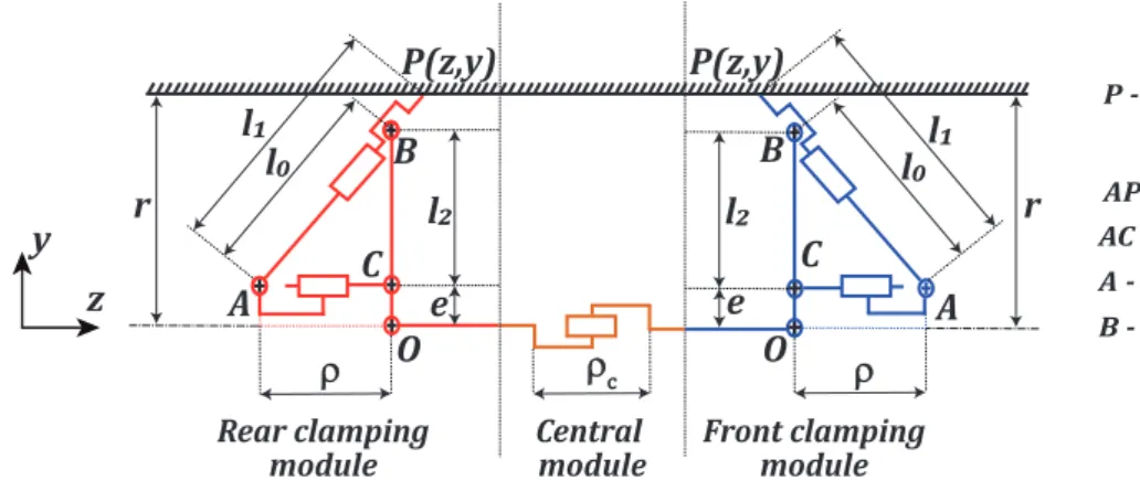
The robot proposed in [7],[8] mimicks the locomotion of a caterpillar. The general motion of a cater-pillar comprises of a front and rear elongation module and a central blocking module. Anthierens el al. [9] developed a similar inchworm type electro-pneumatic robot that uses bellows to accomplish this locomotion. However, inside nuclear power plant pipelines there exists dust particles and deposits which limits the use of bellows and it is complex to apply a force control algorithm for systems using bellows. Electrical actuators are thus used in the robot to accomplish the caterpillar locomotion which is accomplished in six steps [8]. The outline of the robot inside a pipeline of radius r is shown in Figure1.
P(z,y) Central module B A O r rc r O r A B P(z,y) r Front clamping module Rear clamping module e l! l" l" e l! l# l# C C
AP - Slot follower leg
A - Passive rotary joint B - Passive prismatic joint
P - Leg contact point with pipeline walls
AC - Active prismatic link
z y
Figure 1: Outline of the robot inside a pipeline of radius r
A slot-follower leg mechanism is used in the front and rear modules to have contact with pipeline walls during locomotion. In Figure1, AP represents the slot-follower leg. O is the reference point for the leg mechanism. AC represents the active prismatic link which has a stroke length of ρ. The leg is hinged at B in order to slide and have contact with pipeline walls. The stroke length of the central module is represented by ρc. A Maxon EC motor (brushless DC motor) coupled with a Maxon spindle drive is
used to accomplish the clamping and elongation processes. The specifications of the motor and spindle drive are provided below in Tables1-2.
Table 1: Specifications of the Maxon EC-motor (Part No. 283828) [10]
Parameters Value Nominal voltage 12 V Nominal current (Ic) 0.456 A No load speed 13500 rpm No load current (In) 60.2 mA Nominal speed 5840 rpm Efficiency (ηm) 54 %
Torque constant (KT) 7.82 mNm/A
Speed constant (Nv) 1220 rpm/V
For the control of motors, three ESCON 36/3 servo controllers offered by Maxon [10] are used, with one controller for each motor. This controller ensures speed and torque control of the motor units. Using the motor units, spindle drive, coupling screws and standards fasteners such as circlips, studs, nuts and bolts,
Table 2: Specifications of the Maxon Spindle drive (Part No. 424749) [10]
Parameters Value
Spindle screw diameter and pitch (p) φ5 x 2 mm Reduction ratio (G) 455:1 Max. static axial load 500 N Max. spindle length 102 mm
Efficiency (ηs) 63 %
the entire robot can be assembled. A 3D model of the robot is also realized using CATIA software†.
2.2
Interfacing with BB black and ESCON controllers
For the command and control of the robot, a BeagleBone (BB) black micro-computer is used. The BB black offers 92 pins which comprise of the Pulse-Width modulation (PWM), General-Purpose In-put/Output (GPIO), Analog to Digital converters (ADC) and reconfigurable digital ports [11]. Each Maxon motor is interfaced with the BB black through their ESCON 36/3 servo controller by three pins. One pin is connected to the PWM which is used to operate a motor on a duty cycle in a particular direc-tion. The other pin is connected to a GPIO which is used to enable or disable the motor functioning in a boolean way. The third pin is connected to the ADC to read the motor voltage. The PWM of the BB provides a maximum voltage of 3.3 V and it is used to operate the motors with control over the speed. For the idle stage, 50% duty cycle is set as a reference where the current is 0 A. For the safe running of motors, 80% of the duty cycle of the PWM is only used. At 80% duty cycle the motor performs either clamping or retraction operation with clockwise rotation and at 20% duty cycle the motor performs de-clamping or elongation operation with anti-clockwise rotation. The interfacing between BB black and one set of EC motor and its controller is provided in Figure2.
In Figure2, the J2 cable of each ESCON controller is connected to its EC motor unit. The J1 cable of each controller is connected to a power source of 12 V. The cables J5 and J6 are connected to the PWM, GPIO and ADC pins of BB black. The PWM, GPIO and ADC pin address on BB black for each motor and its servo controller is listed below in Table3.
Table 3: BB black pin address for each motor and its servo controller Motor PWM (duty cycle) GPIO (Enable/Disable) ADC (Results) Motor-1 P9_14 (DigIN 1) GPIO_14 (DigIN 2) AIN0 (AnOUT 1) Motor-2 P8_13 (DigIN 1) GPIO_47 (DigIN 2) AIN1 (AnOUT 1) Motor-3 P9_31 (DigIN 1) GPIO_68 (DigIN 2) AIN2 (AnOUT 1)
Before the start of experiments, the DC motors and ESCON controllers are calibrated in a computer through a USB cable through port J7 as per the specifications mentioned in Tables1-2. The output voltages from PWM which are generally analog is passed to the ADC to display the outputs to the user. The ADC of BB black, however, supports a maximum voltage of 1.8 V. Thus, the output analog voltage before passing to ADC of BB black is calibrated in the ESCON software in accordance with the nominal current of the motor. The BB black also offers Enhanced Quadrature Encoder Pulse (eQEP) pins which can be used to determine the position/displacement of robot at any instance of locomotion. However, this feature is not included in the current control loop of the robot. The control methodology for the
†
3D model of the robot in CATIA and simulation available in -https://www.youtube.com/watch?v=7z6-by83mtw
Motor winding 1 Motor winding 2 Motor winding 3 Hall sensor 1 Hall sensor 2 Hall sensor 3 +5 VDC Hall sensor EC Motor Motor winding 1 Motor winding 2 Motor winding 3 Hall sensor 1 Hall sensor 2 Hall sensor 3 +5 VDC 100k 100nF 100k J2 J2A +10...36 VDC Power supply 1 J1 2 1 2 3 4 5 6 DigIN 1 DigIN 2 DigIN/OUT 3 DigIN/OUT 4 +5 VDC J5 +Vcc USB USB Data-USB Data+ VBUS J7 AnIN 1+ AnIN 1-AnIN 2+ AnIN 2-AnOUT 1 AnOUT 2 J6 PWM (BB) GPIO (BB) ADC (BB) GND (BB) GND(BB)
Maxon motor control ESCON 36/3 EC
PW PWM M GPIOIO ADC C GND D GND(D(D(D( BeagleBone (BB) black
Figure 2: Layout of the interface between BB black to one EC-motor and its servo controller
locomotion will be explained in the next section.
3
Control methodology- Force control algorithm
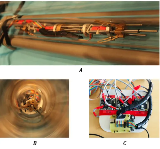
In the real world application, the robot under study will be implemented for inspection inside dark pipelines with no visual information about its current position. A force control algorithm is employed which is used to control the locomotion of robot inside an environment of unknown size. By applying the necessary clamping force from the power source to the motors, the robot can adapt its legs and clamp itself to pipeline walls. Initially, interfacing between BB black and each motor as well as its servo controller is done as per Figure2. The BB black is connected to a computer and this board operates on Debian OS 7.9. The activation of pins‡ specified in Table3 are done using the linux terminal of BB black micro-computer. When a PWM duty cycle is applied to the motor, the spindle drive enables the leg mechanisms to clamp or de-clamp or allow the central motor to elongate or retract. The motors rotate at a constant speed during its duty cycles. A simpler form of the pseudo-code for one forward motion is provided in Algorithm1in Appendix. At the end of one loop cycle, the robot remains in an over-constrained posture wherein both the leg mechanisms are clamped with the walls of the pipeline. The prototype of the robot developed at LS2N, France is depicted in Figure3.
In Figure3, A represents the working of robot inside a test pipe and in B, the side view of the robot is shown. In C, the ESCON controllers for the robot is represented. The following operations are
‡
Pin activation of BB black in Debian 7.9 available
in-https://github.com/stvt1991/Control-of-piping-inpsection-robot/tree/master/ Pin-activation
Figure 3: Prototype of the robot developed at LS2N, France**
performed using C program†† for the locomotion of the robot which is written as per Algorithm1: • Forward motion (twice)
• Reverse motion (twice)
In order to ensure that there is no continuous running of motors after an operation is finished, threshold limits are being set for the clamping/retraction as well as de-clamping/elongation phases. The upper threshold TUis set at 1.5 V which is 83% of the maximum voltage of ADC and the lower threshold is set
at 0.42 V. These values are determined based on experimental trials. Also, these values are ideal when operating inside variable sections as the diameter of any locomotion step is unknown. When the limits are reached, the torque reaches its stall point and the PWM is set to idle phase.
4
Results of experiments for a locomotion cycle
With the interfacing between controllers and BB black being done, the parameters defined below in Table4are calibrated for the ESCON controllers before the algorithm is initiated. The experiment is carried out inside a 2.5 m length PVC transparent tube of 74 mm diameter as depicted in Figure3. The ADC of the BB black generates the output voltage which is extracted and the results can be traced in
∗∗
Photography copyrights: Vincent Jacques, Centrale Nantes, France
††
Force control algorithm written in C language available
Table 4: ESCON controller calibration before initiation of Force-control algorithm PWM Duty cycle ADC voltage (V) Nominal current (A) Motor speed (rpm)
20% 0 -0.46 10800 (Counter-clockwise)
50% (idle) 0.9 0 0
80% 1.8 0.46 10800 (Clockwise)
MATLAB. The results of output voltage of each motor for two forward and reverse motions is depicted in Figure4. 0 20 40 60 80 100 120 140 160 Time (s) 200 400 600 800 1000 1200 1400 1600 1800 2000 2200
Output voltage from ADC (mV)
M1-Left leg actuator M2-Central actuator M3-Right leg actuator Lower threshold Upper threshold
Figure 4: Output voltages of motors measured from ADC during experiments
The total time taken for the completion of the entire algorithm is 179 seconds. At 89.5 seconds, two sets of forward motions are completed and the reverse motion is initiated. At the end of experiments, the robot returns to its initial position to an over-constrained posture. The de-clamping operation on both legs could be performed to take out the robot. In Figure4, the red and blue lines indicate the left and right leg actuators. The orange lines highlight the central motor. The threshold voltages are indicated by black and gray lines. It could be observed from the results that higher noises are generated in the output voltage of ADC. There are several factors which could contribute to these noises. When one set of leg mechanisms are clamped and the other end is free, a bending phenomenon was observed which could lead to potential numerical errors in the measure. In order to overcome this issue, a numerical filter is applied. Using MATLAB, the frequency of the noise is measured. With the help of Savitzky-Golay filtering technique in MATLAB [12], the measured frequency is matched with the desired frequency of BB black (2 kHz) for reducing the noise.
Using the smoothened output voltages, the current induced on the actuators can be estimated by the equation:
I = VtIc Vidle
− Ic (1)
In Eqn. (1), Vtis the ADC output voltage at a given time t of the locomotion cycle. Icis the nominal
taken as 0.9 from Table4. However, the current value obtained from Eqn. (1) does not provide the actual current as there exists power losses in the DC motor that is generated due to the resistance of the windings. The actual current measured from the motor is given by:
Ia= I − In (2)
Here, Inis the no-load current of motor and this value is subtracted from the result of Eqn. (1) to obtain
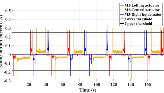
the actual current induced in the motor. The results of actual current induced on each motor during the locomotion cycle is represented in Figure5.
20 40 60 80 100 120 140 160 Time (s) -0.3 -0.2 -0.1 0 0.1 0.2 0.3 0.4 0.5
Motor output current (A)
M1-Left leg actuator M2-Central actuator M3-Right leg actuator Lower thershold Upper thershold
Figure 5: Actual currents induced on motors during the experiments
It could be observed in Figure5that smoother results are obtained with the application of filter. Also, higher starting voltages and currents are observed for each motor when a duty cycle is applied. This is because the motor rotates at a constant velocity and the time taken to attain this velocity when a duty cycle is applied is very short. This can be however rectified by following a motion profile such as "bang-bang", where the velocity is gradually increased until it reaches a constant value [13]. The de-clamping operation of motors M 1 and M 3 is not done completely in order to achieve larger displacements as the output velocity of the spindle drive is very low of around 0.43 mm/s [14]. However, the central actuator always extends/retracts to a maximum and this could be observed in Figures4and5.
With the help of the output currents, the torques induced on the motors followed by the forces can be calculated by the below equations.
τ = IaKT G ηmηs (3)
F = 2πτ
p (4)
The parameters in Eqns. (3)-(4) such as the torque constant (KT), gear ratio (G) and efficiencies (ηm
drive. The output forces and torques can then be studied for comparison with the results of simulation estimated in [14].
5
Conclusions and future works
The control of a bio-inspired piping inspection robot was studied in this article. Using a BB black micro-computer, the robot was tested inside a transparent PVC pipe of 74 mm diameter for a period of 179 seconds. It was possible to study the voltage induced on the motors during the cycle using the ADC of BB black. By applying numerical filters, the results were smoothened in order to derive the actual currents induced on the motors after power losses. The currents generated can then be used for estimating torques and forces induced on the motors during the locomotion cycle. The force control algorithm allowed us to carry out the experiments "blind" without going through a complex procedure. By experimental trails, the threshold limits were derived wherein the forces necessary to clamp the robot with pipelines walls can be attained. Higher threshold limits cannot be set as they not only damage the motors but also can possibly deform the leg mechanisms after the contact is established.
The force control algorithm allowed us to test the robot inside a pipe of 74 mm diameter. However, with varying pipeline diameters, it cannot be assured that the same threshold limits can hold good. This is one of the major limitations of this algorithm. In order to overcome this issue, in the future, the existing BB black will be replaced by a BB blue micro-computer. With the BB blue, the eQEP can be incorporated to the robot and it will be possible to detect the displacement of legs for an unknown pipeline diameter. The algorithm will be extended with the eQEP that will have a relation between leg displacement and the threshold limits. Another advantage of the BB blue is that it requires comparatively lesser cables for connection between the ESCON controllers over the existing BB black.
References
[1] E. Upton and G. Halfacree. Raspberry Pi user guide. John Wiley & Sons, 2014. [2] A.G. Smith. Introduction to arudino a piece of cake, 2017.
[3] G. Coley. Beaglebone black system reference manual. Texas Instruments, Dallas, 2013.
[4] F. Leccese, M. Cagnetti, and D. Trinca. A smart city application: A fully controlled street lighting isle based on raspberry-pi card, a zigbee sensor network and wimax. Sensors, 14(12):24408– 24424, 2014.
[5] A. Yusupov and Y. Liu. Development of a self-propelled capsule robot for pipeline inspection. In
2016 22nd International Conference on Automation and Computing (ICAC), pages 84–88. IEEE, 2016.
[6] M. Abdellatif, H. Mohamed, M. Hesham, A. Abdelmoneim, A. Kamal, and A. Khaled. Mecha-tronics design of an autonomous pipe-inspection robot. In MATEC Web of Conferences, volume 153, page 02002. EDP Sciences, 2018.
[7] R. Henry, D. Chablat, M. Porez, F. Boyer, and D. Kanaan. Multi-objective design optimization of the leg mechanism for a piping inspection robot. In ASME 2014 International Design
Engi-neering Technical Conferences and Computers and Information in EngiEngi-neering Conference, pages V05AT08A001–V05AT08A001, 2014.
[8] D. Chablat, S. Venkateswaran, and F. Boyer. Mechanical design optimization of a piping inspection robot. In 28th CIRP Design conference, 2018.
[9] C. Anthierens, A. Ciftci, and M. Betemps. Design of an electro pneumatic micro robot for in-pipe inspection. In ISIE’99. Proceedings of the IEEE International Symposium on Industrial Electronics
(Cat. No. 99TH8465), volume 2, pages 968–972. IEEE, 1999.
[10] Maxon motors,program 2017/18. high precision drives and systems. http://epaper. maxonmotor.com/. Accessed: 2017-12-15.
[11] Beaglebone black. https://elinux.org/Beagleboard:BeagleBoneBlack. Ac-cessed: 2018-06-29.
[12] Savitzky-golay filtering. https://fr.mathworks.com/help/signal/ref/ sgolayfilt.html. Accessed: 2018-08-28.
[13] W. Khalil and E. Dombre. Modeling, identification and control of robots. Butterworth-Heinemann, 2004.
[14] D. Chablat, S. Venkateswaran, and F. Boyer. Dynamic model of a bio-inspired robot for piping inspection. In ROMANSY 22–Robot Design, Dynamics and Control, pages 42–51. Springer, 2019.
Appendix
Algorithm 1 Forward sequence force algorithm 1: Initialization
Hyper − static posture
2: while ADC of M 1 < TUdo . TU- Upper threshold: Operation of motor till stall torque 3: Front leg modules clamping: M1 rotation at constant speed
4: end while
5: while ADC of M 2 < TUdo
6: Central module retraction: M2 rotation at constant speed 7: end while
8: while ADC of M 3 < TUdo
9: Rear leg modules clamping: M3 rotation at constant speed 10: end while
Advancement of robot . Two forward motions ensured by a f or loop 11: for i = 1 − 2 do
12: while ADC of M 1 > TLdo . TL- Lower threshold: Operation of motor till stall torque 13: Front leg modules de-clamping: M1 rotation at constant speed
14: end while
15: while ADC of M 2 > TLor (t < 2s) do . Estimation of stroke as a function of speed 16: Central module elongation: M2 rotation at constant speed
17: end while
18: while ADC of M 1 < TU do
19: Front leg modules clamping: M1 rotation at constant speed 20: end while
21: while ADC of M 3 > TLdo
22: Rear leg modules de-clamping: M3 rotation at constant speed 23: end while
24: while ADC of M 2 < TU do
25: Central module retraction: M2 rotation at constant speed 26: end while
27: while ADC of M 3 < TU do
28: Rear leg modules clamping: M3 rotation at constant speed 29: end while
30: end for