HAL Id: hal-02372713
https://hal.archives-ouvertes.fr/hal-02372713
Submitted on 20 Nov 2019
HAL is a multi-disciplinary open access archive for the deposit and dissemination of sci-entific research documents, whether they are pub-lished or not. The documents may come from teaching and research institutions in France or abroad, or from public or private research centers.
L’archive ouverte pluridisciplinaire HAL, est destinée au dépôt et à la diffusion de documents scientifiques de niveau recherche, publiés ou non, émanant des établissements d’enseignement et de recherche français ou étrangers, des laboratoires publics ou privés.
Energy absorption capacity of composite thin-wall
circular tubes under axial crushing with different trigger
initiations
J.E. Chambe, Christophe Bouvet, Olivier Dorival, Jean-François Ferrero
To cite this version:
J.E. Chambe, Christophe Bouvet, Olivier Dorival, Jean-François Ferrero. Energy absorption capacity of composite thin-wall circular tubes under axial crushing with different trigger initiations. Journal of Composite Materials, SAGE Publications, 2019, pp.002199831987722. �10.1177/0021998319877221�. �hal-02372713�
1
Energy absorption capacity of composite thin-wall circular tubes under axial
crushing with different trigger initiations
J.E. Chambe1, C. Bouvet1*, O. Dorival1,2, J.F. Ferrero1
1Institut Clément Ader, Université de Toulouse, CNRS UMR 5312, INSA / ISAE-SUPAERO / Mines Albi / UPS,
Toulouse, France
2 Icam, Toulouse, France
* Corresponding author: christophe.bouvet@isae.fr
Abstract:
The purpose of this study is to evaluate and compare the ability of various composite structures to dissipate the energy generated during a crash. To this end, circular composite tubes were tested in compression in order to identify their behavior and determine their absorbing capabilities using the Specific Energy Absorption (SEA) (energy absorbed per unit weight). Several composite tubular structures with different materials and architectures were tested, including hybrid composition of carbon-aramid and hybrid configuration of 0/90 UD with woven or braided fabric. Several inventive and experimental trigger systems have been tested to try and enhance the absorption capabilities of the tested structures. SEA values up to 140 kJ.kg-1 were obtained, achieving better than most
instances from the literature, reaching around 80 kJ.kg-1. Specimens with 0°-oriented fibers
coincidental with the direction of compression reached the highest SEA values while those with no fiber oriented in this direction performed poorly. Moreover, it has consequently been established that in quasi-static loading, a unidirectional laminate oriented at 0° and stabilized by woven plies strongly meets the expectations in terms of energy dissipation. Incidentally, an inner constrained containment is more effective in most cases, reducing the initial peak load without drastically reducing the SEA value.
2 Introduction:
CFRP are known to be effective energy absorbing structures, due to the highly dissipative damage mechanisms involved during severe solicitations [1-4]. For that reason, in addition to their lightness combined with interesting mechanical properties, they are present in various domains: automotive [5-7], railway [8-9], aeronautics aircrafts [10-11], and helicopters [12-14], all of which may be subjected to brutal impact resulting in a violent crash.
Damage mechanisms resulting from the crushing of composite structures have been identified on CFRP plates [15-17] and tubes [2-3,10,18-20] structures.
Failure mechanisms that contribute the most to the energy dissipation depend on various factors that include delamination, bending, kinking and fracture of the fibers as well as fracture of the matrix [5].
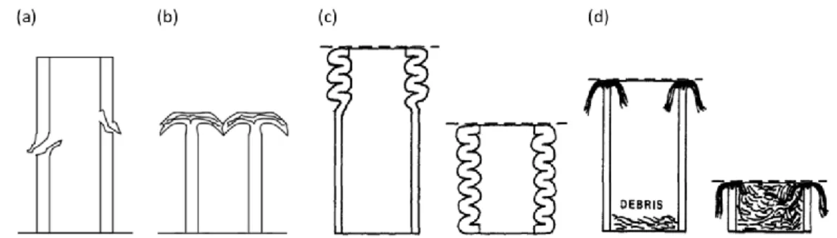
Two main failure mechanisms for composite tubular structures have been identified as either catastrophic or progressive failure (Fig. Figure 1) [2,18]. For the latter failure mode, a distinction can be made as the composite tube may undergo progressive folding or progressive crushing [19] (Fig. Figure 1). During the first case, composite tube walls progressively fold under successive local buckling (similar to shell buckling) when loaded in axial compression. The extremity of the tube yields in buckle mode, leading to hinge formation and progressive folding; the folded zone then grows progressively down the tube wall. For the second case, the tube collapses as a result of successive brittle fractures. The extremity of the tube breaks leading to the splaying of the tube’s wall and multiple fragmentations. Local fracture occurs at the crush front; splaying and micro-fractures then propagate down the tube [19]. Such a rupture mode tends to generate random sized debris.
Figure 1: Catastrophic (a) and progressive (b) failure [2,18], progressive folding (c) and crushing (d) [19].
In progressive crushing mode, damage mechanisms at the structural scale may be summed up into three types: (i) splaying, (ii) fragmentation and (iii) debris creation and accumulation [17,19,20] (Fig. Figure 2).
3 Figure 2: Major damage mechanisms occurring at the crush zone (adapted from [19]).
Fragmentation might occur at two levels: under the tip of the plies (due to micro-buckling of fibers for 0° plies and to multiple shear micro-cracks for 90° plies) or within the plies as intra-laminar failure, fiber breakage and matrix cracks (due to a combination of compression, bending and shear) [17,19] (Fig. Figure 2).
The internal stress generated in the splayed fronds lead to at least four identified failure modes, according to [19]. Although it is dependent on the fracture strengths of the material, for a unidirectional lamina ply, those failure modes are (a) tensile failure on the surface normal to the fronds, (b) compressive or shear fracture, (c) compressive buckling, and (d) intra-laminar shear fracture parallel to the fibers (Fig. 3).
In addition, [20] links the cracks density – and therefore the energy absorbed – to the radius of curvature of the splayed parts. A large radius of curvature leads to a lower number of cracks, hence less energy absorbed, whereas a small radius of curvature leads to high crack density and higher energy absorbed.
Figure 3: Four identified failure modes for splayed fronds (adapted from [19]).
The successive stages of composite tube progressive crushing have been well identified [19,21,22] as displayed in Figure 4.
4 Figure 4: Consecutive crushing stages from [21].
The localized fragmentation at the tip of the plies is pointed as the mechanism leading to the definition of the ply Mean Crushing Stress (MCS) [16,17], corresponding to a stable crushing level (Fig. 4(f)), occurring after the yielding peak (Fig. 4(b,c)) and stabilization phase (Fig. 4(e)).
Recent studies take their interest in the Mean Crushing Stress characterization [16,17] on standalone plies and within laminates as well as the influence of fibers orientation or braided structure effect and the use of mix or hybrid materials on the crushing level.
Most research works focus on means to increase the Energy Absorbed while reducing the initial peak load to enhance crushing performances. To that end, a multitude of factors have been studied. The crashworthiness properties and energy absorption characteristics of structures with different cross-sectional shapes and geometries have been studied [23], including in particular, sine-wave beams [10,13], semi-hexagonal specimens [24], columns specimens [25], conical shells [26-28] or various tubular shapes [26-30] and corrugated tubes [26,27,31,32].
Foremost tubular shapes tested are circular [1-5,8-9,18,26-27,39-43] or squared [5,18,26-27,37,44-49]. Most studies find the energy absorption capability of squared tubular structures to be 0.5 times lower than that of circular ones.
Tube scaling [5,35], and especially the effect of thin-walled tubes and the influence of wall thickness [14,20,23,25,28,42,46-50] have been considered, generally highlighting an energy absorption increase trend with the increase of the wall thickness.
Investigations have also been carried out on materials types used to manufacture the structures, mainly including Carbon, Glass and Aramid fibers, with a various range of polymeric resin: Carbon [7,10,47] Carbon/Epoxy [2,5,10,13,16-20,33-37,45], Carbon/PEEK [3,33,35,52], Carbon/Vinylester [37,41,46], Carbon/Polyamide [40], Glass/Epoxy [10,12,18,28,31,38,43], E-glass/Polyester [5,24,26-27,44], Glass/Vinylester [26], Glass/Polypropylene [40], Kevlar/Epoxy [1,5,8,9], hybrid materials [1,5], composite metal-fibers [23,48], hybrid Aramid/Carbon/Epoxy [13] or even woven silk/Epoxy [49]. [53] proposes a review of the energy absorption capability and the crashworthiness of composite material and metal structures, giving values recorded for axially compressed FRP and metal tubes clearly highlighting the superiority of FRP structures over steel structures.
A comparison with steel and aluminum, with SEA values of 15 and 30 kJ.kg-1, respectively [20] places
FRP energy absorption capacity significantly above. [33] reports a value of 53 kJ.kg-1 for 45° oriented
5 reinforced thermosetting resin composites [33]. He also presents a value of 110 kJ.kg-1 obtained for
Carbon/Epoxy tubes [19]. This in accordance with [34] reporting values of 85 to 120 kJ.kg-1 for
Carbon/Epoxy tubes. Those values are significantly below the 127 kJ.kg-1 obtained for 30° oriented
carbon fibers/PEEK tubes and the 180 kJ.kg-1 obtained in the 0° carbon fibers/PEEK tubes [33].
The effect of fibers orientation [1,5,7,11-14,25,32-39,45-46], as well as the laminate stature, UD [5,7,11,13,16,17,26,27,30,39,43], 2D woven or braided structure [7,20,26,27,31,34,37,40,42,43,47] and even triaxially braided composite tubes [36,37,40,41,46] have also been tested in previous works.
The crushing behavior of composite tubes is found to be dependent on the fiber content and the fiber architecture [33-34]. Tubes with lower fiber contents crushed irregularly whereas tubes with fiber contents above 15% crushed progressively [34].
The relative amounts of 0° and 90° fibers as well as their position in the stratification of the tube’s wall is a major factor that determine the geometry of the crush zone and therefore the specific energy absorption [33].
Similarly, previous works demonstrated that a fiber orientation along the axis of the composite tube absorbed more energy than other orientations [1,12,32]. In that sense, many studies report a significant decrease of the energy absorption capacity with greater fiber orientation for Carbon/Epoxy tubes [12,36].
Congruently, [36] finds that when varying the braided angle of composite laminate structures for composite tubes, the smallest braiding angles produce the highest specific energy absorption, up to 89 kJ.kg-1 for a 20° angle, (and 100 kJ.kg-1 for 15° [12]) and reports a clear decline of the SEA value as
the braiding angle increases, down by almost 50% to 45 kJ.kg-1.
[34] concludes that the specific energy absorption capability increases with an appropriate fiber content and that the insertion of inlay fibers into the knitted fabric is an effective method of improving the energy absorption capability of fabric composite tubes.
Improving the crushing initiation with specific trigger geometries or profiles [44], tulip shape [49], notched outlines [1,26,27], different tapered angles [43], SMA trigger (shape memory alloy wires) [39], inserting lateral circular cutouts [50] or by chamfering or beveling the edge [1,3,12,16-20,26-27,33-36,46] or using a double-chamfer trigger (chamfered at both ends) [38] has been attempted. The use of plug initiators [20,37,41-42,46-47] is also a recurring attempt to initiate and enhance the crushing.
Finally specific boundary conditions with chamfer external triggers [42] or semi-circular cavity external trigger [42] have recently been tested. [42] states that the energy absorption is improved by 53% by replacing a chamfer trigger with innovative trigger, with values ranging from 45 up to 102 kJ.kg-1 for 2D-braided Carbon/Epoxy tubes.
To jump over the main points, two significantly exploitable axes of interest are standing out: materials and fibers orientation choice on one hand and trigger initiation and boundary conditions optimization on the other. These are the two aspects presented in this study (Part A and Part B). The present study will relate to the experimental testing results of several circular composite tubes of different compositions and stratification. More specifically various combinations of unidirectional and woven structures as well as hybrid Carbon-Aramid reinforcement fibers are being tested. A first
6 part will focus on the effect of different stratification and materials in a simple free-face crushing configuration (Part A).
A second part will present the effect of different trigger initiation systems on the crushing performances using mainly one singular sample, before highlighting specific features for each tube sample in some of the configurations (Part B).
The work presented in this study therefore aims at comparing the results in Energy Absorption capability of hybrid composite circular structures with different fibers orientations and of different natures (UD, woven) using specific boundary conditions and trigger initiation systems.
Experimental testing:
Specimens and materials
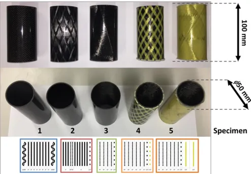
A variety of fiber/Epoxy tubes were acquired for testing, with different fibers orientations and fibers types. These fiber-reinforced tubular structures were studied in axial compressive crushing. In total, five specimens with different structures and different compositions were tested in various crushing configurations. Structural and material basis for the specimens include 12K HR carbon fibers and polymer Epoxy resin. Fibers orientation and laminate stratification differ from one specimen to another as shown in Figures 5 and Figure 6 and summarized in Table 1. Provided tubular structures were machined and shaped in tubes of 100 mm length as pictured in Figure 5. Medium diameter was set at an average of 50 mm, with inner diameter varying from one sample to another due to stacking differences. Stratification layout and tube wall thickness are summarized in Table 1 for each sample. The Carbon/Epoxy combination was selected with Epoxy resin as a matrix because of its low density and for its high strength and good mechanical properties with reliable chemical stability, as well as its worthy performance regarding energy absorption based on the literature review and due to the aeronautical context.
Figure 5: Picture of the five tube specimens with dimensions.
In order to verify and establish the composition and stratification of the composite tubes specimens, samples were polished and observed using a high resolution optical microscope. Measurements and images acquisitions were performed using an Alicona Infinite Focus SL microscope system with a x10
7 to x50 magnification. Resulting observations are displayed in Figure Figure 6, along with a lay-up schematization.
Figure 6: Microscopic observations of the five specimens section and corresponding schematic representations with their stratification.
For the laminate lay-up schematization presented in Figure Figure 6, the 0° direction of the fibers was chosen to coincide with the longitudinal axis of the tube and subsequently with the axial crushing
8 direction. Plies dimensions are given as an averaged best approximation since plies thickness is not even and regular. That is supposedly the results of the fabrication process.
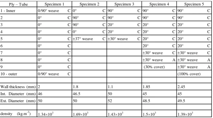
Table 1 reports the structural specificities and geometrical properties for the 5 tube specimens.
C: Carbon A: Aramid Table 1: Tubes specimens stratifications and properties.
When looking at the density values from Table 1, it can be pointed out that they are relatively low for some samples (sample 1 especially, and to a lesser extent, sample 3). This is allegedly strongly related to the high porosity observed in the samples (Fig. Figure 6) and also lower fiber density (or fraction volume vf) in some areas of the samples.
Table 2 intends a comparison in Stiffness and Compressive strength failure between experimentally and theoretically obtained values for all five samples. Both the experimental and theoretical methods used to achieve those results are presented below. The magnitude referred to as Stiffness (in MPa) relates to the elastic compressive modulus (Young’s modulus).
Table 2: Stiffness and Compressive strength properties for tube sample stratifications. Ply – Tube 1 - Inner 0/90° weave C 0° C 90° C 90° C 90° C 2 0° C 90° C 90° C 90° C 90° C 3 0° C 90° C 20° C 20° C 20° C 4 0° C 0° C 20° C 20° C 20° C 5 0° C 37° weave C 30° weave C 20° C 20° C 6 0° C 20° C 20° C 7 0° C 30° weave C 30° weave C 8 0° C 30° weave A 30° weave A 9 0° C (30% cover) 30° weave A
10 - outer 0/90° weave C (100% cover)
Wall thickness (mm) 2 1.8 1.1 1.85 2.45
Int. Diameter (mm) 46 46.5 50 45 45
Ext. Diameter (mm) 50 50 52 48.5 49.5
density (kg.m-3) 1.34×10³ 1.69×10³ 1.43×10³ 1.5×10³ 1.39×10³ Specimen 1 Specimen 2 Specimen 3 Specimen 4 Specimen 5
Stiffness (MPa) Compressive strength (MPa) +2800 +100 -5200 -139 +4900 +65 -3100 -102 +8700 +47 -8600 -92 +6800 +44 -6000 -59 +3600 +29 -5400 -41 Theoretical Compressive strength (MPa) Experimental Tube 1 43 700 -350 54 200 -650 Tube 2 Tube 3 Tube 4 Tube 5 54 300 30 200 27 300 24 700 -652 -265 -259 -250 Stiffness (MPa) -340 -170 -180 -200 52 100 22 800 24 500 23 600
9 For the five tubular specimens (and especially for tube samples 1 and 2) materials and fibers properties are not well known and identified nor completely mastered. Compressive experimental testing shows that fibers mechanical properties are less resistant than usually encountered in current modern composite materials.
In order to better estimate the mechanical properties of the materials used to manufacture these samples, and to correlate the theoretical and experimental stiffness, Classical Lamination Theory was used. Taking a failure criterion expressed in fibers compression strain, chosen at failure = -0.0125 for
all the plies, an estimated stress failure value was calculated for each sample, for the first ply reaching failure, and reported in Table 2. For the woven plies of the structures, mechanical properties
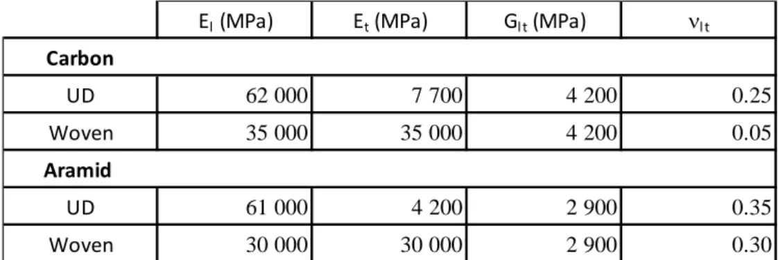
were also calculated using the Classical Lamination Theory but the related plies were approximated as two superposed oriented unidirectional plies of half the thickness. The mechanical stiffness properties used for the theoretical calculations with the Classical Lamination Theory are reported in Table 3, where El is the longitudinal modulus, Et the transverse modulus, Glt the shear modulus and
lt Poisson’s ratio.
Table 3: Mechanical properties used for the Classical Lamination Theory calculations.
When comparing values from the theoretical calculations to the experimental data (Table 2), the latter reflects lower values in stress failure, although it can be noted that they remain in the same order of magnitude. Besides, the experimental compressive strength values that are reported in Table 2 are rather related to a failure in crushing mode than pure compression.
Figure Figure 7 presents the experimental mechanical stiffness modulus obtained from quasi-static axial compression testing of samples 1 to 5 positioned under 2 crushing plane.
El (MPa) Et (MPa) Gl t (MPa) l t
Carbon UD 62 000 7 700 4 200 0.25 Woven 35 000 35 000 4 200 0.05 Aramid UD 61 000 4 200 2 900 0.35 Woven 30 000 30 000 2 900 0.30
10 Figure 7: Compression stiffness from experimental testing of axial crushing for tubes 1 to 5. Those compression tests were performed on each sample along the axial direction and a compression stiffness modulus was experimentally evaluated while the materials remained in their elastic deformation, as presented in Figure Figure 7 and reported in Table 2.
Results reported in Table 2 show that the compression stiffness is lower than anticipated for 3 of the 5 CFRP specimens, especially for specimens 1 and 3. Compression failure is also lower than estimated, especially for specimens 1 and 2 that incidentally mainly present 0°-oriented fibers. This supports the hypothesis of poor fibers’ properties used to manufacture the tubular specimens, and it can also be explained by the high porosity inherent to many samples, as observed on the microscopic images (Fig. Figure 6). This is also most obvious for tube specimen 1, for which braided thread remnants from the manufacturing process are visible too. In addition, experimental compressive failure values resulting from the performed compression tests could rather be affected by a bearing phenomenon under the tip of the plies and resulting from the crushing nature of the solicitation than related to a pure compressive mode, hence the observed discrepancy in compression strength failure, which thereafter seems more rational.
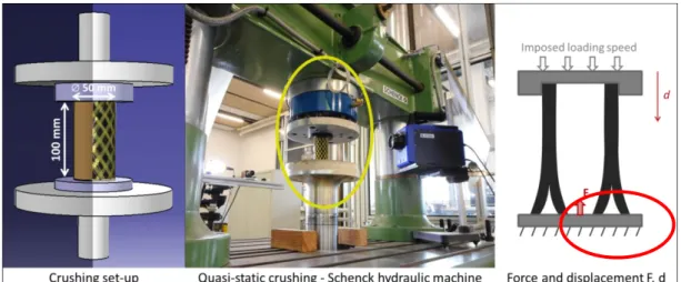
Test set-up and configurations
Quasi-static crushing tests were carried out using a 250 kN Schenck hydraulic testing machine in compression testing mode, through a constant loading speed of 0.2 mm.s-1 (Fig. Figure 8). To account
for reproducibility, tube specimens were tested at least 3 to 5 times on average (and up to 10 times) for each sample and each configuration.
11 Figure 8: Quasi-static crushing test set-up and equipment.
Experimental results:
Part A
This first part presents the experimental results for the free face axial compressive crushing of the 5 CFRP circular tubes mentioned above between two plane surfaces.
Figure Figure 9 represents the Stress-Displacement curve resulting from such trials, for tube specimen 1. The stress thereby represented corresponds to an average value from multiple trials for the same specimen and the same testing configuration, with the dispersion range indicated on both sides of the curve.
Figure 9: Stress-Displacement curve and dispersion for tube 1.
Generally it can be noted a relatively good repeatability in the trials, especially for composite material, with a dispersion averaging -12% and +32% compared to the medium value, as illustrated in Figure Figure 9. Overall, less than 2% of the total of tested samples has been discarded for being deemed aberrant.
A crushing curve such as the ones displayed in Figures Figure 9 and Figure 11 can be divided into three main parts: a loading phase ending by the main rupture of the structure and leading to a peak, a stabilization phase and a stable crushing phase [19,22]. Sometimes, when crushing is extended long
12 enough, a last phase known as compaction of debris or densification may occur, matching an increase of the end of the curve.
Once reached, the level of the crushing threshold or Mean Crushing Stress (MCS) [Erreur ! Source du renvoi introuvable.,Erreur ! Source du renvoi introuvable.] is very steady and regular from one trial to another. The compression stiffness is also mainly identical from one trial to another. However, it can be observed a large dispersion on the peak value itself, with random values being reached before a structure failure.
In practical terms, this uncontrolled dispersion on the crushing peak and its higher values are not wanted for a crash absorption system, as it produces important accelerations for the structure and therefore the passengers. With this standpoint in consideration, several configurations and crushing initiations have been tested in order to limit this main peak.
Figure 10: Crushed CFRP tubes specimen 1 to 5, from the top (above) and from the side (below) Apart from the multitude of resin and fibers debris generated during crushing, splaying (both inward and outward) and large bands of material resulting from intra-laminar shear are a consequence of composite laminate crushing, as seen on picture in Figure Figure 10.
A difference can be observed between tubes samples 1 and 2 presenting both inner and outer spreading of splayed parts and tubes samples 3, 4 and 5 mainly presenting outer spreading. This can be explained mostly by the core structure of the tubular samples, with oriented-fibers pattern (specimens 1 and 2) and unoriented-fibers pattern (specimens 3, 4 and 5).
Additionally, a specificity can be mentioned for samples with an aramid overlayer (tube specimens 4 and 5) as this latter acts as a girdle, drawing the shattered composite parts, resulting in a closer folding and wrapping around itself.
Figure Figure 11 presents the crushing stress over the axial displacement for the 5 tube specimens in axial crushing.
13 Figure 11: Stress-Displacement curves of axial crushing of tubes 1 to 5.
Two groups of CFRP tube specimens can be made from the Stress-Displacement curves resulting from axial compression, with tubes 1 and 2 averaging a higher value of nearly 140 MPa for the MCS plateau and tubes 3 to 5, lowering at 75 MPa. This is directly resulting from the structure and stratification of the tubes specimens, which can consequently be separated into two groups: group 1: oriented-fibers tubes (tube specimens 1 and 2) and group2: unoriented-fibers tubes (tube specimens 3, 4 and 5).
Overall, this result seems rational as composite fibers need to be unidirectionally oriented in the loading direction (in this case, 0°) to return a maximal stress value. This is in accordance with previous studies [1,12,32-34,36]. Nevertheless, some transversally oriented fibers are still required to stabilize the whole structure, as it is the case for tube specimen 1, where the woven pattern for the upper and lower ply is present to stabilize the unidirectional core and which coincidentally happens to be the strongest sample.
Finally, it can be noted that the length of the stabilization phase is directly linked to the wall thickness of the tube specimens; it corresponds to approximately twice the thickness (Fig. Figure 11, Table 1).
14 Figure 12: Stress/density over Displacement curves of experimental crushing for tubes 1 to 5. One means to characterize and compare the absorbing capability of materials is through the Specific Energy Absorption (SEA), also referred to as Specific Sustained Crush Stress. The SEA value is given by the following equation (Eq. 1):
SEA =
EA
m
=
1
. u
∫ (u
∗)du
∗ u 0 Eq. (1)where EA is the Energy Absorbed (given by the area under the force-displacement curve), divided by the mass of the crushed mater m. is the compression stress, u the crushing distance, and the density of the material.
It can be established that the SEA value can be very closely approximated as an instantaneous value using the crushing stress cr divided by the density of the crushed material (Eq. 2).
SEA
→ 𝑐𝑜𝑛𝑠𝑡
→
𝑐𝑟 Eq. (2)Although displaying a similar stress level value for the MSC plateau (Fig. Figure 11), when related to their respective density, tube 1 and 2 differ greatly in term of absorption capability (Fig. Figure 12), with tube 1 presenting an average of 110 kJ.kg-1 and tube 2 of 80 kJ.kg-1 while the second group of
specimens show lower values, near 55 kJ.kg-1.
Similarity in behavior and energy absorbing capability for specimens 3, 4 and 5 are not incoherent when referring to Table 1, which shows the same basis structure for those specimens. Outer aramid covering does not improve or worsen the general behavior or energy absorbing capability.
Once the transition phase has passed, the SEA value tends toward a constant value, as displayed in Figure Figure 13. The influence of the peak can be noticed at the very beginning of the curve and a displacement of at least 10 mm is needed to erase the effect of this peak.
15 Figure 13: SEA evolution for 5 CFRP tube specimens submitted to pure axial crushing.
The histogram chart shown in Figure Figure 14 displays the average SEA values for each tube sample in free axial crushing. They are presented side-by-side with a factor, referred to as overshoot, and defined by the crushing stress initial peak maximum value divided by the density (Eq. 3). This indicator was chosen to represent and compare the overflow of energy for each sample.
Overshoot =
𝑚𝑎𝑥
Eq. (3)As the overshoot is uniform to the SEA (kJ.kg-1) a direct comparison between these two values is
possible and it can be revealed that for each specimen, the overshoot is at least twice as high as the SEA value (x2 for tube specimen 3, x2.5 for tube specimen 1 and up to x2.8 for tube specimen 5).
16 Some instances in the literature refer to the Load Uniformity or Trigger Ratio defined as Fmax / Fmean
or Crushing Load Efficiency defined as Fmean / Fmax [54]. The overshoot parameter was deemed more
suited to represent the overflow of energy than the other parameters or ratios from the literature. Furthermore, as it is homogenous to the SEA, the comparison between the two magnitudes is made easier.
In order to limit the peak and therefore reduce the overshoot, several boundary conditions and crushing initiations have been tested.
Intermediate conclusion
To summarize the first part of this experimental work, the following observations can be made. Failure mechanisms remained similar for all tube samples, with moderate to significant splitting, delamination and multiple brittle crack paths, leading to large debris creation.
Tubular specimens with 0° fibers oriented in the loading axial direction perform better in compressive strength and therefore return higher SEA values.
Woven fabric plies help containing and guiding the unidirectional plies, restraining them from splaying too easily.
Aramid fibers bring no additional rigidity or energy dispersion capability but aramid covered tube samples contain the fragmented carbon/matrix wreckages better, avoiding large spillage.
Part B
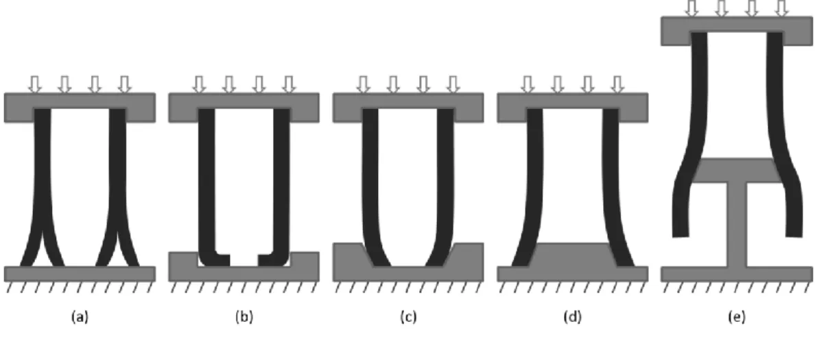
Several configurations were tested for crushing initiation improvement and hopeful energy absorption enhancement. Tubular structures were clamped and encased at one end at the top, while several options were tested for the other end at the bottom. They were (a) let free on a plane surface, (b) also encased, (c) encased while guided through a conic shape, (d) positioned on a conic plug initiator, and (e) submitted to pure flaring, where the structure gradually becomes wider from one end to the other, as a conic part passed through. Figure Figure 15 presents the five configurations tested.
Figure 15: Experimental testing configurations (a) to (e).
((a) free Crushing, (b) Inner Crushing, (c) Inner Conic Crushing with sloping initiation, (d) Outer Conic Crushing with plug initiation, (e) pure plug flaring)
17 For the two conic-shaped configurations ((c) and (d)), specific conic-shape parts were designed and machined for each specimens according to the specificity of each tube’s internal diameters (Table 4), with a goal of expressing a hoop strain of 20000 µ and –15000 µ respectively via the gradual slope. Those values are usual approximations of tension and compression stain ruptures for composite materials. A detailed schematization (Fig. Figure 16) gives the diametric information that is reported in Table 4.
Figure 16: Outer (left) and Inner (right) conic-shaped parts used to change the boundary conditions.
Table 4: Conic-shaped parts specifications and dimensions for inner and outer cones.
For the outer cone (forcing a hoop strain of 0.020), the diameter of the base of the conic part (Dint)
was made to match the Interior diameter (Int. diam.) of the tube and for the inner cone (forcing a compressive hoop strain of – 0.015), the diameter of the base of the conic-shaped part (dext) was
made to match the Exterior Diameter (Ext. Diam.) of the tube. Specifications are reported in Table 4.
Figure 17: Crushed CFRP tubes (1) showing outer spreading (left) and inner folding (right) based on boundary condition (a) free crushing and (b) Inner crushing, respectively.
Tube Specimen 1 Specimen 2 Specimen 3 Specimen 4 Specimen 5
Int. diameter (mm) 46 46.5 50 45 45
Ext. Diameter (mm) 50 50 52 48.5 49.5
Outer Cone (20 000 µ) Outer Cone 1 Outer Cone 2 Outer Cone 3 Outer Cone 4 Outer Cone 5
Outer Cone dint (mm) 44 44.6 47.9 43 43
Outer Cone Dint (mm) 46.9 47.5 50.9 45.9 45.9
Inner Cone (15 000 µ) Inner Cone 1 Inner Cone 2 Inner Cone 3 Inner Cone 4 Inner Cone 5
Inner Cone Dext (mm) 52 52 54 50.5 51.5
18 As an illustration, the pictures in Figure Figure 17 present the difference in crushing behavior for the same CFRP tube specimen (tube 1) submitted to axial crushing under the first two configurations ((a) and (b)) presented in Figure Figure 15. Both underwent progressive crushing. The first (left) corresponding to configuration type (a) presents both inner and outer spreading of splayed parts, whereas the second (right) corresponding to configuration (b), reveals the whole bundle of splayed parts folding towards the inside of the tube.
Configuration type (d), with a cone-shaped plug initiator, does not differ much from configuration type (a) apart from the fact that the entire splayed bundle spreads on the outside and configuration type (c), with an inner-conic-shaped part, does not differ from configuration (b). This can also be correlated by the tomographic images.
Figure 18: Stress/density over Displacement curves of experimental crushing for tube specimen 1 submitted to axial crushing under 5 configurations.
Figure Figure 18 displays the Stress/density over Displacement results for tube specimen 1, for the 5 described configurations. In case of inner-crushing confinement (b), a slight but still significant increase of the curve can be noted towards the end, starting at 40 mm (). This rise should even be starting sooner, at about 23 mm (half the tube’s interior diameter)(), when the wall’s inferior end meets at the center of the tube (Fig. Figure 19).
Surprisingly, this outcome is not seen for configuration (c) (inner conic crushing) where the end of the tube’s wall also meets at the center. This might be explained by the fact that the tube’s wall’s ends are too damaged or too much fractured by the friction and the progressive confinement induced by the conic sloped part.
19 Figure 19: Schematic representation of the tube’s wall convergence and collision, for the
inner-crushing configuration (with tube specimen 1 dimensions).
This increase of the stress at the end could be beneficial and valuable for a surge in the SEA value: the densification of partially crushed material inside the tubular structure stabilizes the crushing process, resulting in an increase of the mean crushing stress and therefore the SEA.
For configurations with a conic initiation (inner or outer), (c) and (d) respectively, hoop stress is first generated, and axial crushing force takes longer to apply as the interior diameter of the tubular structure slides along the conic slope, before being axially loaded, as can be seen on Figure Figure 18 for configurations (c) and (d), between 0 and 3 mm displacement.
Figure 20: Outer and inner conic parts and initial tube position.
The very beginning of the Stress-Displacement curve for those two configurations matches the last configuration (e), where the conic-shaped plug widens the extremity of the tubular structure. This setback is incidental to the height of the conic shape () (Fig. Figure 16, Figure 20).
Pure flaring (configuration (e)) was tested to try and take advantage of the crimping property of woven structures in braided composite tubes (Fig. Figure 21). Furthermore, the idea was to compare configuration (d) with configurations (a) and (e) and evaluate if the total energy dissipated by (d) was the summation of (a) and (e). Needless to say when referring to Figure Figure 18, that this is hardy the case, with configuration (e) only dissipating 1 or 2% of the energy compared to pure axial crushing (configuration (a)).
20 In braided or woven patterns, the crimping can be characterized by the ratio of the real length of the fully deployed fiber (B) divided by the actual length of this fiber within the woven pattern (A) (Fig. Figure 21, Eq. 4):
Crimping =
B
𝑙𝑒𝑛𝑔ℎ𝑡× 100
A
𝑙𝑒𝑛𝑔ℎ𝑡 Eq. (4)Overall, although trying to make the most of the crimping configuration in woven patterns seemed promising and worth investigating, this attempt unfortunately proved to be unpractical and non-optimal in terms of energy dissipation afterwards.
The histogram chart shown in Figure igure 22 displays the average SEA values side-by-side with the overshoot for tube specimen 1 for the 5 crushing configurations.
Figure 22: SEA and overshoot values for tube specimen 1 for the 5 configurations.
For each axial compression tests, a stiff peak can be observed on the Stress/density-Displacement curves as showed in Figure Figure 18, when the structure yields before it starts collapsing by progressive crushing at a stable and constant stress, as reflected by the continuous plateau level. Ideally the gap between the peak and plateau value has to be reduced to a minimum, as a small gap and constant plateau level means an optimized dissipation of energy for a fixed and given load value. In case of outer crushing, the use of a conic plug initiator (d) to introduce a radial flaring of the tube structure before it is submitted to crushing does not improve the energy absorbing capability, compared to pure and plain crushing (a), as shown in Figure Figure 18 and igure 22. Configuration (d) does not reduce the overshoot either (Fig. igure 22). Moreover, this configuration worsens the energy absorbing capability at it significantly lowers the SEA value (Fig. Figure 18 and igure 22). At last, the use of the conic plug alone, passing through the tube along its whole length and inducing an axial flaring of the structure (configuration (e)) hardly dissipate any energy, leading to the conclusion that the expansion of the crimping fibers is not a primordial mechanism in composite absorption capability. For this reason, results from configuration (e) will mostly be disregarded in the following discussions.
21 However, notwithstanding the current results, it is essential to keep in mind that configurations (d) and (e) are highly dependent on the dimensions of the conic plug initiator, which may have been improperly chosen to achieve the goal of reducing the overshoot. A more complete and focused study on more adequate dimensions of the conic slope may be needed, with a series of tests imposing a gradual strain deformation (0.005, 0.010, 0.015, 0.020, 0.025…) for instance.
Tomographic imaging
Post-testing X-Ray micro-measurement observations were conducted to observe and determine the damage mechanisms involved during crushing on the inside of the tubes’walls thickness. X-Ray 3D-micro-computed tomography images were performed using a Micro-Tomography EasyTom 130 machine, manufactured by RX Solutions, France. The tubular specimens were placed at a distance of 91.3 mm from the source. The source has a voxel size of 18 μm. Each specimen was scanned through a 360° rotation using a Varian PaxScan 1313DX imager to capture layer-by-layer 2D X-ray images used for full-scale 3D reconstruction. RX Solutions X-Act 2.0 software was used for 3D reconstruction and post-processing. Due to the samples size and dimensions the maximum possible and workable resolution was 18 μm.
The source-object distances (sod) and source-detector distances (sdd) were 91.3 mm and 643.9 mm respectively, which determine the magnification (sdd/sod) at 7.05. The X-ray voltage and current were set to 60 kV and 133 mA respectively. Each sample was scanned for 160 min with 0.6 s per projection.
Figure Figure 23 (a): free Crushing
22 Figure Figure 23 (c): Inner Conic Crushing
Figure Figure 23 (d): Outer Conic Crushing
Figure 23: Tomographic images and schematizations of crushed CFRP tubes showing major damage and plies dispersion for specimen 1 in four configurations ((a), (b), (c) and (d)).
Figure Figure 23 highlights major occurring damage mechanisms resulting from progressive crushing instigated by quasi-static axial compression load for tube specimen 1 through the means of tomographic imaging for four different crushing modes ((a), (b), (c) and (d) when referring to Figure Figure 15). Inner (a), (b), (c) and outer (a), (d) splaying of fragmented or un-fragmented parts are clearly visible, as well as debris accumulation.
The high porosity of the tube specimen is also visible, black shaped holes and lines on the inside of the tube’s wall, confirming the visual observations from the microscopic images.
The crushing plane surface is schematized by a discontinued line on all pictures in Figure Figure 23. It is strongly suspected that for each tube samples, folded plies at the end of the tube walls between the sane part of the tubes and the crushing surface moved back downward when the crushing force was unloaded, due to a spring-back effect. Hence an estimated positioning of the crushing surface appearing to be situated within the tube and entering inside the tube structure. Similarly, positions of the boundary parts and conic-shaped parts were added.
For the first configuration (a), a pyramidal-shaped debris accumulation can be observed at the center under the tube wall, between the tube section and the crushing surface, where the laminate plies spread towards the inside or the outside of the tubular structure. This debris accumulation forms
23 from the void created by the plies splaying from the center under the tube wall then subsequently helps further and heighten this splaying.
At the contact surface between the tube circular section and the plane surface, micro-bucking occurs progressively and successively, resulting in matrix and/or fibers fragmentation for the laminate plies that undergo such splaying. This damage mode increases the debris formation. As observed and mentioned in previous study, the formation and the evacuation or accumulation of debris remains rather random.
For the second test configuration (b), damage mechanisms are similar in type and classification, but are all shifted toward the inside of the tube, since the outer wall is encased, leaving no leeway for splayed plies to spread that way. Incidentally, although major occurring damage are the same, their origin varies somewhat. Bending and folding resulting from the compression generate the splaying of the composite plies, and therefore the fracture and fragmentation for those sustaining a higher stress. Fragmentation still generates an important number of debris that varies in forms and shape, but those are freely evacuated from the crushing zone under the tube section to the inside of the tube. They do not form a tip that parts the laminate wall and split it, as observed with the pyramidal debris accumulation on the first configuration.
At the extremity of the tube wall, where the folding appears, outer plies seem to be more submitted to bending whereas inner plies undergo plain compression and break through intra-laminar fracture. According to the tomographic imaging, configuration (c) is almost identical to configuration (b) but appears to be less densified at the center, on the inside of the tube’s wall. This might explain why no increase of the crushing stress is observed on the crush-displacement curves for that configuration. The inner slope inclination favored the “folding” of the inner fabric ply by guiding it, contrary to configuration (b) where it was more abruptly fractured.
For the last test configuration (d), outer splaying is mainly predominating, since the conic shape blocked the inner splaying and spreading towards the interior of the tube. On the interior side of the tube, splaying is almost nonexistent. However fragmentation is intensified, with large fractures, of both the fibers and the matrix. Additionally, the tube wall went back to its initial position, once the metallic conic part was withdrawn, due to a vertical spring back effect and the wall’s rigidity.
It appears from images in Figure Figure 23, that for every configuration tested (except configuration (e)), there are always 3 or 4 plies damaged by fragmentation while the 7 or 6 remaining plies are only bent in splaying. The 3 or 4 fragmented plies are always inside plies of the tube’s structure.
Those inner plies are the most impacted and the most solicited plies during crushing, creating a localized fragmentation that leads to a localized crushing which characterizes the Mean Crushing Stress defined by [Erreur ! Source du renvoi introuvable.,Erreur ! Source du renvoi introuvable.]. This would explain the overall crushing stress (crushing) always averaging around 150 MPa, for every
configuration tested (except configuration (e), which underwent no crushing at all.) as displayed in Figure Figure 24. It can be inferred from that observation that this definite number of fragmented plies is optimum in order to optimize the SEA value.
24 Figure 24: Mean Crushing Stress values for tube specimen 1 for the 5 configurations.
Some notable observations were made for other tube specimens in other configurations, as pointed out in the following section.
For the inner-crushing configuration (b), tubes specimens 3, 4 and 5 displayed two major modes of failure. Figure Figure 25 presents that distinction in failure behavior mode observed for some samples in inner-crushing configuration (b) using tube specimen 3 as an example. Those two modes, namely catastrophic failure and progressive crushing, were reported to occur by [2,18], and previously illustrated in general crushing case by Figure Figure 1 (a) and (b).
Figure 25: Stress-Displacement curve and dispersion for tube specimen 3 and inner-crushing configuration.
Although in most instances tube specimens 3, 4 and 5 behaved according to a usual progressive crushing mode, in some cases, they underwent catastrophic failure from a middle point of the tubular structure and without undergoing progressive crushing from one end. Visual illustrations of
25 the catastrophic failure mode demonstrated by those samples are given with pictures in Figure Figure 26.
This unwanted failure mode drastically lowers the SEA value for these samples in this particular configuration to 13.1 kJ.kg-1 for specimen 3 and 26.5 and 27.4 kJ.kg-1 for specimen 4 and 5, while they
stand at 52.8, 44.7 and 52.8 kJ.kg-1 respectively when progressive crushing occurs in this
configuration.
The ratio of catastrophic failure stands at 25%, 33% and 50% for tube specimens 3, 4 and 5 respectively, in inner-crushing configuration (b), when these tubes displayed a 99.8% progressive crushing successful behavior in all other configurations.
Figure 26: Pictures of CFRP tubes specimen 3, 4 and 5 which underwent catastrophic failure for inner-crushing configuration (b).
In practical terms, inner-crushing configurations reduced the production and scattering of debris, as the undamaged part of the tube act as a sheath as can be seen on pictures in Figure Figure 17. To that extend, tube specimens 4 and 5 (the two specimens that have an aramid cover on top of the carbon structure) do not present any interest regarding the SEA value, but the aramid cover acts as a girdle, helping in folding and containing the fragmented parts, both in case of inner and outer crushing. This comes at the expense of a lower compression stiffness and a lower tubular section to conserve a similar density, when comparing with tube sample 3 and referring to Table 1.
Figure Figure 27 summarizes the Specific Energy Absorption average values obtained for all tube samples (1 to 5) in all configurations ((a) to (e)), with dispersion marks for each testing.
26 Figure 27: SEA average values for the 5 CFRP tube specimens submitted to axial crushing
in 5 configurations.
For tube specimen 1 inner-crushing (b) seems to enhance the SEA while inner-conic crushing (c) lowers the value (for the chosen conic dimensions). A complementary study on the conic slope inclination might be needed to test different angle dimensions and confirm that result.
For tube specimen 2 inner-crushing (b) enhances the SEA and inner-conic crushing (c) seems to improve it a little more (with the margin of dispersion taken into account). This improvement might come from the 90°-oriented plies that are more solicited in confined compression. As a result, the overall crushing stress increases and therefore so does the SEA.
Tube specimen 3 performs the most irregularly. In addition to the catastrophic failure mode observed for configuration (b) – which has been discarded for the SEA average calculation in Figure Figure 27 – tube specimen 3 shows the biggest dispersion, especially in configuration (b) (Inner Crushing). The lowest SEA values obtained for this sample may be the result of some crushing instabilities, which might be the consequence of the small thickness of the tube’s wall, as that specimen displays the thinness wall thickness when referring to Table 1. Too thin a wall thickness may lead to some unstable crushing phenomena and most notably affect the buckling modes.
Inner-conic crushing (c) seems to work better for specimens with 90°-oriented fibers (specimens 2, 4 and 5, except specimen 3) for the same reasons mentioned above (i.e. confined compression and adequate tube wall thickness), while it can also be noted that they all contain some plies with a fiber orientation at 0° or close to 0° (specimen 2 has 0°-oriented fibers, specimens 4 and 5 have 20°-oriented fibers).
It can also be surprisingly noted that tubes specimens 4 and 5 performed well in configuration (c) whereas tube 3 performed poorly in that configuration and that they performed poorly on any other configurations too. This is all the more surprising as they are both covered with Aramid layer(s) and that Aramid fibers are known to withstand weakly in compression. This can be explained by their relatively bigger thickness (Table 1 and Fig. Figure 6), about twice as much as tube 3, and the increase of 20°-oriented plies in number, doubling from specimen 3 (Fig. Figure 6).
27 For all samples (1 to 5), outer-conic crushing (d) lowers the SEA value and degrades the structure absorbing capacity. Failure phenomena involved are primarily the same as described by [19] and presented in Figure 3. For this configuration, while fiber rupture in traction is energetically very dissipative, it is also very localized, whereas crushing, which is slightly less dissipative, could repeatedly happen on a whole area.
The difference in results between inner and outer crushing (both in plain and conical configurations) is fully in accordance with the statement formulated by [20] on the relation between cracks density and the radius of curvature of the splayed parts.
Conclusions:
Quasi-static axial crushing tests were performed on composite circular tubes with 5 different structural compositions and using 5 different trigger initiation configurations.
SEA values up to 140 kJ.kg-1 were obtained, achieving better than most instances from the literature,
averaging around 50 kJ.kg-1 and reaching up to around 100 kJ.kg-1 for braided Carbon/Epoxy
structures.
Specimens with 0°-oriented fibers in the axial loading direction achieved better in energy absorption than specimens with no fibers in that direction. It has consequently been established that in static loading, a unidirectional laminate oriented at 0° and stabilized by woven plies strongly meets the expectations in terms of energy dissipation. Incidentally, an inner constrained containment is more effective in most cases, reducing the initial peak load without drastically reducing the SEA value. Woven reinforcement on the inner and outer wall structure proved more effective than solid strengthening supports such as metal constraints or poured resin in providing stability to the structure. Additionally, the woven plies help containing the 0°-oriented fibers from splaying and flaring too easily. Moreover, as such woven plies are structurally required for stability reasons, it is opportune to try and put them in beneficial use, hence the inner oriented crushing concepts, which load and stress these fibers in crushing.
However, the additional aramid draping was proven needless in term of energy absorbing capacity. Yet this overlapping covering may be valuable in acting as a net to refrain outer spreading by directing splayed chunks and debris towards the inside and keep brittle parts within the inside of the tubular structure, avoiding expelled debris, as could be required in an aeronautical context.
In order to complete this study and provide complementary understanding regarding the crushing of fiber-reinforced composite tubes and SEA enhancement, considerations may be given to the following actions:
- varying the strain rate and conducting a study on dynamic crushing,
- varying the slope inclination and the conic dimensions, especially for the inner-conic concept, - chamfering the samples and combining that trigger initiation technique with the presented
boundary conditions,
- using mechanically known fibers and materials, that is to say constituents for which properties are independently tested and identified to permit the best selection.
28 References:
[1] FARLEY, G.L. Energy Absorption of Composite Materials, Journal of Composite Materials, Volume 17, No. 3, May
1983, Pages 267-279, ISSN 0021-9983, DOI 10.1177/002199838301700307.
[2] THORNTON, P.H. The Crush of Fiber-Reinforced Plastics. In: CHEREMISINOFF, N.P. (Ed.), Handbook of Ceramics and
Composites Volume 1: Synthesis and Properties. Marcel Dekker Inc., New York, New York, 1990, Pages 307-337, ISBN: 0-8247-8005-1.
[3] HAMADA, H., RAMAKRISHNA, S., SATOH, H. Crushing mechanism of carbon fibre/PEEK composite tubes,
Composites, Volume 26, Issue 11, 1995, Pages 749-755, ISSN 0010-4361, DOI 10.1016/0010-4361(95)98195-Q.
[4] MAMALIS, A.G., ROBINSON, M., MANOLAKOS, D.E., DEMOSTHENOUS, G.A., IOANNIDIS, M.B., CARRUTHERS, J. Crashworthy capability of composite material structures, Composite Structures, Volume 37, Issue 2, February 1997,
Pages 109-134, ISSN 0263-8223, DOI 10.1016/S0263-8223(97)80005-0.
[5] THORNTON, P.H., HARWOOD, J.J., BEARDMORE, P. Fiber-reinforced plastic composites for energy absorption purposes*, Composites Science and Technology, Volume 24, Issue 4, 1985, Pages 275-298, ISSN 0266-3538, DOI
10.1016/0266-3538(85)90026-0.
[6] JACOB, G.C., FELLERS, J.F., SIMUNOVIC, S., STARBUCK, J.M. Energy Absorption in Polymer Composites for Automotive Crashworthiness, Journal of Composite Materials, Volume 36, No. 7, April 2002, Pages 813-850, ISSN
0021-9983, DOI 10.1177/0021998302036007164.
[7] BISAGNI, C., DI PIETRO, G., FRASCHINI, L., TERLETTI D. Progressive crushing of fiber-reinforced composite structural components of a Formula One racing car, Composite Structures, Volume 68, Issue 4, May 2005, Pages 491-503, ISSN
0263-8223, DOI 10.1016/j.compstruct.2004.04.015.
[8] KIM, J.S., YOON, H.J., LEE, H.S., KWON, T.S. Energy Absorption Characterization of Composite Tubes for Railway Application. In: Proceedings of the 17th International Conference on Composite Materials (ICCM), 27-31 July 2009,
Edinburgh, Scotland, UK.
[9] KIM, J.-S., YOON, H.-J., SHIN, K.-B. A study on crushing behaviors of composite circular tubes with different reinforcing fibers, International Journal of Impact Engineering, Volume 38, Issue 4, April 2011, Pages 198-207, ISSN
0734-743X, DOI 10.1016/j.ijimpeng.2010.11.007.
[10] FARLEY, G.L., JONES, R.K. Energy-Absorption Capability of Composite Tubes and Beams. NASA Technical
Memorandum, NASA TM-101634 - AVSCOM Technical Report 89B.003, AVSCOM TR-89-B-003, NASA Langley Research Center, Hampton, VA, USA - Aerostructures Directorate USAARTA (AVSCOM), Hampton, VA, USA, September 1989.
[11] HEIMBS, S., STROBL, F., MIDDENDORF, P., GUIMARD, J.M. Composite Crash Absorber For Aircraft Fuselage Applications, WIT Transactions on The Built Environment, Volume 113, 2010, Page 3-14, ISSN 1743-3509, DOI
10.2495/SU100011.
[12] FARLEY, G.L., JONES, R.M. Crushing Characteristics of Continuous Fiber-Reinforced Composite Tubes, Journal of
Composite Materials, Volume 26, No. 1, January 1992, Pages 37-50, ISSN 0021-9983, DOI 10.1177/002199839202600103.
[13] McCARTHY, M.A., WIGGENRAAD, J.F.M. Numerical investigation of a crash test of a composite helicopter subfloor structure, Composite Structures, Volume 51, Issue 4, April 2001, Pages 345-359, ISSN 0263-8223, DOI
10.1016/S0263-8223(00)00150-1.
[14] WANG, Y., FENG, J., WU, J., HU, D. Effects of fiber orientation and wall thickness on energy absorption characteristics of carbon-reinforced composite tubes under different loading conditions, Composite Structures, Volume
153, 2016, Pages 356-368, ISSN 0263-8223, DOI 10.1016/j.compstruct.2016.06.033.
[15] CAUCHI SAVONA, S., HOGG, P.J. Effect of fracture toughness properties on the crushing of flat composite plates,
Composites Science and Technology, Volume 66, Issue 13, 2006, Pages 2317-2328, ISSN 0266-3538, DOI 10.1016/j.compscitech.2005.11.038.
[16] ISRAR, H.A., RIVALLANT, S., BARRAU, J.-J. Experimental investigation on mean crushing stress characterization of carbon–epoxy plies under compressive crushing mode, Composite Structures, Volume 96, February 2013, Pages
29
[17] ISRAR AHMAD, H.A.B., RIVALLANT, S., BOUVET, C., BARRAU, J.-J. Finite element simulation of 0°/90° CFRP laminated plates subjected to crushing using a free-face-crushing concept, Composites Part A: Applied Science and
Manufacturing, Volume 62, July 2014, Pages 16-25, ISSN 1359-835X, DOI 10.1016/j.compositesa.2014.03.014.
[18] THORNTON, P.H. Energy Absorption in Composite Structures, Journal of Composite Materials, Volume 13, No. 3,
July 1979, Pages 247-262, ISSN 0021-9983, DOI 10.1177/002199837901300308.
[19] HULL, D. A Unified Approach to Progressive Crushing of Fibre-Reinforced Composite Tubes, Composites Science
and Technology, Volume 40, Issue 4, 1991, Pages 377-421, ISSN 0266-3538, DOI 10.1016/0266-3538(91)90031-J.
[20] BRIGHTON, A., FORREST, M., STARBUCK, M., ERDMAN, D., FOX, B. Strain Rate Effects on the Energy Absorption of Rapidly Manufactured Composite Tubes, Journal of Composite Materials, Volume 43, No. 20, September 2009, Pages
2183-2200, ISSN 0021-9983, DOI 10.1177/0021998309344646.
[21] PINHO, S.T., CAMANHO, P.P., DE MOURA, M.F. Numerical simulation of the crushing process of composite materials, International Journal of Crashworthiness, Volume 9, Issue 3, 2004, Pages 263-276, ISSN 1358-8265, DOI:
10.1533/ijcr.2004.0287.
[22] SUPIAN, A.B.M., SAPUAN, S.M., ZUHRI, M.Y.M., ZAINUDIN, E.S., YA, H.H. Hybrid reinforced thermoset polymer composite in energy absorption tube application: A review, Defence Technology, Volume 14, Issue 4, 2018, Pages
291-305, ISSN 2214-9147, DOI 10.1016/j.dt.2018.04.004.
[23] FAN, Z., LU, G., LIU, K. Quasi-static axial compression of thin-walled tubes with different cross-sectional shapes,
Engineering Structures, Volume 55, October 2013, Pages 80-89, ISSN 0141-0296, DOI 10.1016/j.engstruct.2011.09.020.
[24] ESNAOLA, A., ULACIA, I., ARETXABALETA, L., AURREKOETXEA, J., GALLEGO, I. Quasi-static crush energy absorption capability of E-glass/polyester and hybrid E-glass–basalt/polyester composite structures, Materials & Design, Volume
76, 5 July 2015, Pages 18-25, ISSN 0261-3069, DOI 10.1016/j.matdes.2015.03.044.
[25] GLISZCZYNSKI, A., KUBIAK, T. Progressive failure analysis of thin-walled composite columns subjected to uniaxial
compression, Composite Structures, Volume 169, 2017, Pages 52-61, ISSN 0263-8223, DOI
10.1016/j.compstruct.2016.10.029.
[26] PALANIVELU, S., VAN PAEPEGEM, W., DEGRIECK, J., VAN ACKEREN, J., KAKOGIANNIS, D., VAN HEMELRIJCK, D.,
WASTIELS, J., VANTOMME, J. Experimental study on the axial crushing behaviour of pultruded composite tubes, Polymer Testing, Volume 29, Issue 2, April 2010, Pages 224-234, ISSN 0142-9418, DOI 10.1016/j.polymertesting.2009.11.005.
[27] PALANIVELU, S., VAN PAEPEGEM, W., DEGRIECK, J., VANTOMME, J., KAKOGIANNIS, D., VAN ACKEREN, J., VAN
HEMELRIJCK, D., WASTIELS, J. Crushing and energy absorption performance of different geometrical shapes of
small-scale glass/polyester composite tubes under quasi-static loading conditions, Composite Structures, Volume 93, Issue 2,
January 2011, Pages 992-1007, ISSN 0263-8223, DOI 10.1016/j.compstruct.2010.06.021.
[28] KATHIRESAN, M., MANISEKAR, K., MANIKANDAN, V. Crashworthiness analysis of glass fibre/epoxy laminated thin walled composite conical frusta under axial compression, Composite Structures, Volume 108, February 2014, Pages
584-599, ISSN 0263-8223, DOI 10.1016/j.compstruct.2013.09.060.
[29] LAU, S.T.W., SAID, M.R., YAAKOB, M.Y. On the effect of geometrical designs and failure modes in composite axial crushing: A literature review, Composite Structures, Volume 94, Issue 3, February 2012, Pages 803-812, ISSN
0263-8223, DOI 10.1016/j.compstruct.2011.09.013.
[30] DAVID, M., JOHNSON, A.F., VOGGENREITER, H. Analysis of Crushing Response of Composite Crashworthy Structures, Applied Composite Materials, Volume 20, Issue 5, October 2013, Pages 773-787, DOI
10.1007/s10443-012-9301-8.
[31] ELGALAI, A.M., MAHDI, E., HAMOUDA, A.M.S., SAHARI, B.S. Crushing response of composite corrugated tubes to quasi-static axial loading, Composite Structures, Volume 66, Issues 1–4, October–December 2004, Pages 665-671, ISSN
0263-8223, DOI 10.1016/j.compstruct.2004.06.002.
[32] FARLEY, G.L. Effect of Fiber and Matrix Maximum Strain on the Energy Absorption of Composite Materials, Journal
of Composite Materials, Volume 20, No. 4, 1 July 1986, Pages 322-334, ISSN 0021-9983, DOI 10.1177/002199838602000401.
30
[33] HAMADA, H., COPPOLA, J.C., HULL, D., MAEKAWA, Z., SATO, H. Comparison of energy absorption of carbon/epoxy and carbon/PEEK composite tubes, Composites, Volume 23, Issue 4, 1992, Pages 245-252, ISSN 0010-4361, DOI
10.1016/0010-4361(92)90184-V.
[34] RAMAKRISHNA, S., HULL, D. Energy absorption capability of epoxy composite tubes with knitted carbon fibre fabric reinforcement, Composites Science and Technology, Volume 49, Issue 4, 1993, Pages 349-356, ISSN 0266-3538, DOI
10.1016/0266-3538(93)90066-P.
[35] HAMADA, H., RAMAKRISHNA, S. Scaling effects in the energy absorption of carbon-fiber/PEEK composite tubes,
Composites Science and Technology, Volume 55, Issue 3, 1995, Pages 211-221, ISSN 0266-3538, DOI 10.1016/0266-3538(95)00081-X.
[36] CHIU, C.H., TSAI, K.H., HUANG W.J., Effects of Braiding Parameters on Energy Absorption Capability of Triaxially Braided Composite Tubes, Journal of Composite Materials, Volume 32, Issue 21, 1 November 1998, Pages 1964-1983,
ISSN 0021-9983, DOI 10.1177/002199839803202105.
[37] BEARD, S.J., CHANG, F.-K. Energy absorption of braided composite tubes, International Journal of Crashworthiness,
Volume 7, Issue 2, 2002, Pages 191-206, ISSN 1358-8265, DOI: 10.1533/cras.2002.0214.
[38] SONG, H.-W., DU, X.-W., ZHAO, G.-F. Energy Absorption Behavior of Double-Chamfer Triggered Glass/Epoxy Circular Tubes, Journal of Composite Materials, Volume 36, Issue 18, 1 September 2002, Pages 2183-2198, ISSN
0021-9983, DOI 10.1177/0021998302036018515.
[39] HUANG, J.-C., WANG, X.-W. Effect of the SMA Trigger on the Energy Absorption Characteristics of CFRP Circular Tubes, Journal of Composite Materials, Volume 44, Issue 5, 22 October 2009, Pages 639-651, ISSN 0021-9983, DOI
10.1177/0021998309347572.
[40] PRIEM, C., OTHMAN, R., ROZYCKI, P., GUILLON, D. Experimental investigation of the crash energy absorption of 2.5D-braided thermoplastic composite tubes, Composite Structures, Volume 116, 2014, Pages 814-826, ISSN
0263-8223, DOI 10.1016/j.compstruct.2014.05.037.
[41] McGREGOR, C.J., VAZIRI, R., POURSARTIP, A., XIAO, X., Axial crushing of triaxially braided composite tubes at quasi-static and dynamic rates, Composite Structures, Volume 157, 1 December 2016, Pages 197-206, ISSN 0263-8223,
DOI 10.1016/j.compstruct.2016.08.035.
[42] TONG, Y., XU, Y. Improvement of crash energy absorption of 2D braided composite tubes through an innovative chamfer external triggers, International Journal of Impact Engineering, Volume 111, January 2018, Pages 11-20, ISSN
0734-743X, DOI 10.1016/j.ijimpeng.2017.08.002.
[43] YANG, Y., AHMED, K., ZHANG, R., LIU, R., FORTIN, G., HAMADA, H., MA, Y. A study on the energy absorption capacity of braided rod composites, Composite Structures, Volume 206, 2018, Pages 933-940, ISSN 0263-8223, DOI
10.1016/j.compstruct.2018.08.077.
[44] JIMÉNEZ, M.A., MIRAVETE, A., LARRODE, E., REVUELTA, D. Effect of trigger geometry on energy absorption in composite profiles, Composite Structures, Volume 48, Issues 1-3, 2000, Pages 107-111, ISSN 0263-8223, DOI
10.1016/S0263-8223(99)00081-1.
[45] MAMALIS, A.G., MANOLAKOS, D.E., IOANNIDIS, M.B., PAPAPOSTOLOU, D.P. On the response of thin-walled CFRP composite tubular components subjected to static and dynamic axial compressive loading: experimental, Composite
Structures, Volume 69, Issue 4, August 2005, Pages 407-420, ISSN 0263-8223, DOI 10.1016/j.compstruct.2004.07.021.
[46] XIAO, X., BOTKIN, M.E., JOHNSON, N.L. Axial crush simulation of braided carbon tubes using MAT58 in LS-DYNA,
Thin-Walled Structures, Volume 47, Issues 6–7, June–July 2009, Pages 740-749, ISSN 0263-8231, DOI 10.1016/j.tws.2008.12.004.
[47] McGREGOR, C.J., VAZIRI, R., XIAO, X. Finite element modelling of the progressive crushing of braided composite tubes under axial impact, International Journal of Impact Engineering, Volume 37, Issue 6, June 2010, Pages 662-672,
ISSN 0734-743X, DOI 10.1016/j.ijimpeng.2009.09.005.
[48] BAMBACH, M.R. Axial capacity and crushing of thin-walled metal, fibre–epoxy and composite metal–fibre tubes,
31
[49] ESHKOOR, R.A., OSHKOVR, S.A., SULONG, A.B., ZULKIFLI, R., ARIFFIN, A.K., AZHARI, C.H. Comparative research on the crashworthiness characteristics of woven natural silk/epoxy composite tubes, Materials & Design, Volume 47, May
2013, Pages 248-257, ISSN 0261-3069, DOI 10.1016/j.matdes.2012.11.030.
[50] TAŞTAN, A., ACAR, E., GÜLER, M.A., KILINÇKAYA, Ü. Optimum crashworthiness design of tapered thin-walled tubes with lateral circular cutouts, Thin-Walled Structures, Volume 107, October 2016, Pages 543-553, ISSN 0263-8231, DOI
10.1016/j.tws.2016.07.018.
[51] DE CARVALHO, N.V., PINHO, S.T., ROBINSON, P. An experimental study of failure initiation and propagation in 2D woven composites under compression, Composites Science and Technology, Volume 71, Issue 10, 7 July 2011, Pages
1316-1325, ISSN 0266-3538, DOI 10.1016/j.compscitech.2011.04.019.
[52] HAMADA, H., RAMAKRISHNA, S., SATO, H. Effect of Fiber Orientation on the Energy Absorption Capability of Carbon Fiber/PEEK Composite Tubes, Journal of Composite Materials, Volume 30, No. 8, May 1996, Pages 947-963,
ISSN 0021-9983, DOI 10.1177/002199839603000806.
[53] CARRUTHERS, J.J., KETTLE, A.P., ROBINSON, A.M. Energy absorption capability and crashworthiness of composite material structures: A review, Applied Mechanics Reviews, Volume 51, Issue 10, 01 October 1998, Pages 635-649, ISSN
0003-6900, DOI 10.1115/1.3100758.
[54] MOU, H.L., XIE, J., SU, X., FENG, Z.Y. Crashworthiness Experiment and Simulation Analysis of Composite Thin-Walled Circular Tubes Under Axial Crushing, Mechanics of Composite Materials, Volume 55, Issue 1, March 2019, Pages
![Figure 3: Four identified failure modes for splayed fronds (adapted from [19]).](https://thumb-eu.123doks.com/thumbv2/123doknet/11587495.298476/4.892.173.723.104.332/figure-four-identified-failure-modes-splayed-fronds-adapted.webp)