HAL Id: tel-01745536
https://pastel.archives-ouvertes.fr/tel-01745536
Submitted on 28 Mar 2018HAL is a multi-disciplinary open access
archive for the deposit and dissemination of sci-entific research documents, whether they are pub-lished or not. The documents may come from teaching and research institutions in France or abroad, or from public or private research centers.
L’archive ouverte pluridisciplinaire HAL, est destinée au dépôt et à la diffusion de documents scientifiques de niveau recherche, publiés ou non, émanant des établissements d’enseignement et de recherche français ou étrangers, des laboratoires publics ou privés.
L’interface multi-utilisateur pour le travail collaboratif
avec les multiples représentations de la maquette
numérique
Bo Li
To cite this version:
Bo Li. L’interface multi-utilisateur pour le travail collaboratif avec les multiples représentations de la maquette numérique. Traitement du signal et de l’image [eess.SP]. Ecole nationale supérieure d’arts et métiers - ENSAM, 2017. Français. �NNT : 2017ENAM0065�. �tel-01745536�
N°: 2009 ENAM XXXX
Arts et Métiers ParisTech - Campus de Cluny Institut Image - Le2i
2017-ENAM-0065
École doctorale n° 432 : Science des Métiers de l’ingénieur
présentée et soutenue publiquement par
Bo LI
le 19 décembre 2017
Multi-user interface and its use for collaborative work with multiple
representations of Digital Mock-Up
Doctorat ParisTech
T H È S E
pour obtenir le grade de docteur délivré par
l’École Nationale Supérieure d'Arts et Métiers
Spécialité “ Informatique et traitement du signal ”
Directeur de thèse : Frédéric MERIENNE Co-encadrement de la thèse : Ruding LOU Co-encadrement de la thèse : Frédéric SEGONDS
T
H
È
S
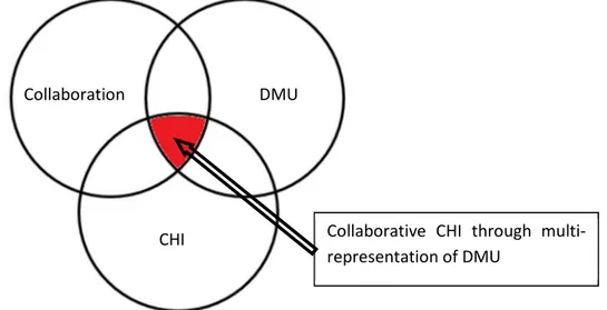
E
JuryM. Frédéric NOEL, Professeur, G-SCOP, Université Grenoble Alpes Président/Rapporteur
M. Bertrand ROSE, Maître de conférences HDR, ICUBE, Université de Strasbourg Rapporteur
Mme Indira THOUVENIN, Professeur, Heudiasyc, Université de Technologie de Compiègne Examinateur
M. Frédéric MERIENNE, Professeur, Le2i, Arts et MétiersParisTech Examinateur
M. Ruding LOU, Maître de Conférences, Le2i, Arts et Métiers ParisTech Examinateur
M. Frédéric SEGONDS, Maître de Conférences, LCPI, Arts et Métiers ParisTech Examinateur
M. Javier POSSELT, Chef de Projet Réalité Virtuelle et Augmentée, CRVSI, Renault Examinateur
Acknowledgments
I would like to express firstly my deep gratitude to my supervisor M. Frédéric MERIENNE, for his great guidance, enthusiastic encouragement, and kind advice throughout my PhD studies. It was a really privilege for me to pursue a new field in last 3 years with his immense scientific knowledge and great personality.
I would also like to thank my co-supervisors, M. Ruding LOU and M. Frédéric SEGONDS, for their continuous support of my PhD study and related research. Ruding’s guidance helped me in all the time of research. We kept discussing and progressing. His patience, motivation and attitude for working have affected me a lot during my work. Frédéric gave me a lot of guidance with his strong knowledge in his field. I was able to benefit from both his innovation in design and experiences in publishing. I felt so lucky to have two such kind and responsible co-supervisors in my PhD.
My grateful thanks are also extended to M. Andras KEMENY and M. Javier POSSELT, for their kind help in discussing many times with my thesis topic, their advices of the application from an industrial point of view as well as the supporting of the experimental devices.
I would also like to extend my thanks to the rest of my thesis committee: M. Frédéric NOEL, M. Bertrand ROSE, and Mme Indira THOUVENIN, for their brilliant comments and suggestions, but also for their questions which incented me to widen my research from various perspectives.
My sincere thanks also go to Institut Image members. Thank M. Thomas LAMY, for his technical support in offering me the resources and research facilities in our laboratory. Thank M. Julien RYARD and M. Sébastien GERIN, for their support in software development and information system. Thank M. Rémy MALIN, for his help with graphics resources. Thank M. Jérémy PLOUZEAU, for many of his suggestions in presentation and many of his help as a graduated PhD in daily life.
I thank my PhD colleagues: M. Chakib BENSEKKA, Mlle. Liza YUSOFF, M. Jose Luis DORADO, for the hard days we were working together before deadlines, and for all the fun we have had in the last 3 years. Thank M. Hongyi ZHANG for his contribution of the experiment during his internship in our lab. Thank all the Master students who have participated in my experiments.
Last but not the least, I would like to thank my parents M. Ming LI and Mme. Yanli ZHANG, for always taking care of me and encouraging me throughout the PhD studies.
Abstract
The current industrial management tools generally rely on Concurrent Engineering, which involves conducting Product Lifecycle Management stages in parallel and integrating technical data for sharing across different experts. Various experts use domain-specific software to produce various data into Digital mock-up. These multidisciplinary experts have trends to work collaboratively during product development. During co-located synchronous collaborative design activities, such as project review and decision-making, experts from different domains must discuss, negotiate, and compromise to solve multidisciplinary differences. Many areas, such as early collaborative design and multi-expert product evaluation, have a great demand for new collaborative support tools. With the development of Human Computer Interaction, it is possible to devise more intuitive tools and methods to enhance co-located collaboration across experts.
In this thesis, to enhance the collaboration with experts on different domains to communicate with DMU, a multi-user interface across users with different representations during a collaborative work has been taken into consideration and its influence on co-located multidisciplinary collaboration is investigated. A schema of the methodology for evaluating the contribution to a multi-user system and the multiple users’ experiences is proposed. Results of experiments show the significances of the efficiency of task, the usability of interface, and the performance of collaboration during the use of multi-user CHI in multidisciplinary collaborative scenarios. The contributions of what multi-user interface brings to the design criteria of multi-user interface and multi-user co-located collaboration are discussed.
Résumé
Les outils actuels de gestion industrielle s'appuient généralement sur l'ingénierie concourante, qui implique la réalisation des étapes de gestion du cycle de vie des produits en parallèle et l'intégration des données techniques pour le partage entre les différents experts. Divers experts utilisent des logiciels spécifiques à leur domaine pour produire diverses données compilées via une maquette numérique. Ces experts multidisciplinaires ont tendance à travailler en collaboration pendant le développement de produits. Au cours d'activités de conception collaborative synchrones, telles que les revues de projet et la prise de décisions, les experts de différents domaines doivent dialoguer, négocier et choisir pour résoudre les différences multidisciplinaires. De nombreux domaines tels que la conception collaborative et de l’évaluation des produits avec multiples experts, ont une grande demande de nouveaux outils d'aide à la collaboration. Avec le développement des technologies de l'Interaction Homme-Machine (IHM), il est possible de concevoir des outils et des méthodes plus intuitifs pour améliorer la collaboration co-localisée entre les experts.
Dans cette thèse, afin d'améliorer la collaboration avec des experts de différents domaines et communiquer via la maquette numérique, une IHM multi-utilisateurs avec des représentations différentes lors d'un travail collaboratif a été pris en considération et son influence sur la collaboration multidisciplinaire co-localisée est étudiée. Un schéma de la méthodologie d'évaluation de la contribution à un système multi-utilisateurs et des expérimentations sont proposées. Les résultats des expériences des résultats significatifs concernant l’efficacité de la réalisation de la tâche, l'utilisabilité de l'Interaction Homme-Machine et la performance de la collaboration lors de l'utilisation de l'interface multi-utilisateurs dans les scénarios de collaboration multidisciplinaires. Les contributions et apports de cette interface sont discutés.
Table of Contents
LIST OF FIGURES _____________________________________________________________________________ 11
LIST OF ACRONYMS _________________________________________________________________________ 15
CHAPTER I INTRODUCTION ________________________________________________________________ 17
Research context ______________________________________________________________________ 17 Problems _____________________________________________________________________________ 17 Research question _____________________________________________________________________ 18 Contributions _________________________________________________________________________ 19 Manuscript structure ___________________________________________________________________ 20CHAPTER II STATE OF THE ART ___________________________________________________________ 21
II.1 Introduction ________________________________________________________________________ 21 II.2 Collaboration _______________________________________________________________________ 21 II.2.1 Definition ________________________________________________________________________ 21 II.2.2 Concurrent engineering _____________________________________________________________ 22 II.2.3 Collaboration working environment ___________________________________________________ 24 II.2.4 Collaboration coupling styles ________________________________________________________ 27 II.3 Digital Mock-Up (DMU) _______________________________________________________________ 29 II.3.1 Definition ________________________________________________________________________ 29 II.3.2 Multi-representation _______________________________________________________________ 31 II.3.3 Interoperability in DMU software _____________________________________________________ 36 II.3.4 Collaborative DMU ________________________________________________________________ 39 II.4 Computer-human interface (CHI) _______________________________________________________ 40 II.4.1 Definition ________________________________________________________________________ 40 II.4.2 CHI modalities ____________________________________________________________________ 41 II.4.3 Mono-user CHI vs. Multi-user CHI _____________________________________________________ 42 II.4.4 Multi-view _______________________________________________________________________ 43 II.4.5 Multi-interaction __________________________________________________________________ 47 II.5 Collaborative CHI through DMU ________________________________________________________ 49 II.5.1. Introduction ______________________________________________________________________ 49 II.5.2. Taxonomy ________________________________________________________________________ 51 II.5.3. Study of applications _______________________________________________________________ 52 II.6 Synthesis of the state of the art and positioning __________________________________________ 58 II.6.1 Synthesis ________________________________________________________________________ 58II.6.2 Positioning _______________________________________________________________________ 58
CHAPTER III SCIENTIFIC APPROACH _____________________________________________________ 61
III.1 Introduction ________________________________________________________________________ 61 III.2 Scientific problem ___________________________________________________________________ 61 III.2.1 Designing a multi-user system _______________________________________________________ 63 III.2.2 Proposal of multi-user collaborative scenario ___________________________________________ 64 III.2.3 Evaluation _______________________________________________________________________ 65 III.2.4 Discussion on the contributions of evaluation ___________________________________________ 69 III.3 Synthesis of the scientific approach _____________________________________________________ 69CHAPTER IV TECHNOLOGICAL BACKGROUND __________________________________________ 71
IV.1 Introduction ________________________________________________________________________ 71 IV.2 Hardware development ______________________________________________________________ 72 IV.2.1 Output hardware: Multi-view display________________________________________________ 72 IV.2.2 Input hardware _________________________________________________________________ 75 IV.3 Software development _______________________________________________________________ 77 IV.3.1 Exchanging network _____________________________________________________________ 77 IV.3.2 Applications ____________________________________________________________________ 78 IV.4 Synthesis of technological background __________________________________________________ 84CHAPTER V EXPERIMENTS _________________________________________________________________ 87
V.1 Experiment of COLLAB_PACMAN simulation game ________________________________________ 88 V.1.1 Description of experiment ___________________________________________________________ 88 V.1.2 Experimental conditions ____________________________________________________________ 89 V.1.3 Hypotheses ______________________________________________________________________ 90 V.1.4 Experimental protocol ______________________________________________________________ 90 V.1.5 Measurement ____________________________________________________________________ 91 V.1.6 Results __________________________________________________________________________ 91 V.1.7 Discussion ________________________________________________________________________ 95 V.2 Experiment of COLLAB_MAZE_3D simulation game ________________________________________ 96 V.2.1 Description of experiment ___________________________________________________________ 96 V.2.2 Experimental conditions ____________________________________________________________ 97 V.2.3 Hypothesis _______________________________________________________________________ 98 V.2.4 Experimental protocol ______________________________________________________________ 98 V.2.5 Measurement ____________________________________________________________________ 99 V.2.6 Results _________________________________________________________________________ 100 V.2.7 Discussion _______________________________________________________________________ 104 V.3 Experiment of MUG collaborative design _______________________________________________ 105 V.3.1 Description of experiment __________________________________________________________ 105V.3.2 Experimental protocol _____________________________________________________________ 107 V.3.3 Measurement ___________________________________________________________________ 108 V.3.4 Results _________________________________________________________________________ 108 V.3.5 Discussion _______________________________________________________________________ 112 V.4 Experiment of CAR ergonomic evaluation _______________________________________________ 113 V.4.1 Description of experiment __________________________________________________________ 113 V.4.2 Experimental protocol _____________________________________________________________ 115 V.4.3 Results _________________________________________________________________________ 117 V.5 Synthesis of experiments ____________________________________________________________ 117
CHAPTER VI CONCLUSION AND PERSPECTIVES _______________________________________ 121
VI.1 Proposed research question __________________________________________________________ 121 VI.2 Contributions ______________________________________________________________________ 121 VI.2.1 State of the art ________________________________________________________________ 121 VI.2.2 Multi-user CHI system ___________________________________________________________ 121 VI.2.3 Multi-user collaborative scenario __________________________________________________ 122 VI.2.4 Evaluations ___________________________________________________________________ 122 VI.2.5 Scientific publications ___________________________________________________________ 123 VI.3 Limitations ________________________________________________________________________ 124 VI.4 Perspectives _______________________________________________________________________ 124APPENDIX A RESUME SUBSTANTIEL EN LANGUE FRANÇAISE _______________________ 127
List of Figures
Figure 1 : Three research areas: collaboration, DMU and CHI. _______________________________________ 21 Figure 2 : The state of the art of collaboration which is one of the three research areas. __________________ 22 Figure 3 : Sequential engineering and concurrent engineering in product lifecycle. _______________________ 23 Figure 4 : Benefits gained during implementing CE (Abdalla, 1999).___________________________________ 24 Figure 5 : Collaborative work is separated into 4 conditions. (Agrawala et al., 1997). ____________________ 25 Figure 6 : Example of project reviews during product lifecycle (Fillatreau et al., 2013) ___________________ 26 Figure 7 : Collaboration styles which influenced how much information was shared among collaborators. ___ 27 Figure 8 : The state of the art of DMU which is one of the three research areas. _________________________ 29 Figure 9 : DMU is a virtual prototype which consists all the technical data of product characteristics (Dolezal, 2008) ____________________________________________________________________________________ 30 Figure 10 : Relation between DMU’s geometry and metadata on a simplified example (Kaun, 2003). ________ 31 Figure 11 : During entire PLM, multiple experts work with one unique DMU. ___________________________ 32 Figure 12 : Multiple experts work with multiple representations and interact with DMU using certain manners. _________________________________________________________________________________________ 33 Figure 13 : Framework describing the early stages of design process (Segonds, 2011). ___________________ 33 Figure 14 : Various models used during the design of an electric motor (MG-IT, 1999). ___________________ 34 Figure 15 : Ergonomic evaluation of Driver, Vehicle, and Environment (Bhise, 2011) _____________________ 35 Figure 16 : Interface among simulation softwares increases interoperability (Schneider et al., 2009). _______ 37 Figure 17 : Master model based approach which contains FEA, CAD and kinetics representations (Bettaieb and Noël, 2008). _______________________________________________________________________________ 37 Figure 18 : BIM model contains different building information. ______________________________________ 38 Figure 19 : Intersection of DMU and collaboration: multi-disciplinary collaboration ______________________ 39 Figure 20 : Software-based and model-based approaches allow users to interact with one master model with one file format. ____________________________________________________________________________ 40 Figure 21 : The state of the art of CHI which is one of the three research areas. _________________________ 40 Figure 22 : Components of a CHI. ______________________________________________________________ 41 Figure 23 : Different styles of collaborative virtual environment (Tuddenham and Robinson, 2009) ________ 43 Figure 24 : Three mechanisms of multi-view system _______________________________________________ 44 Figure 25 : Filter-based multi-view system mechanism _____________________________________________ 44 Figure 26 : Time-based multi-view system mechanism _____________________________________________ 45 Figure 27 : Space-based multi-view system mechanism ____________________________________________ 46 Figure 28 : Intelligent CHI will allow users to interact with optional devices: vision, sound, haptic devices, etc. 47 Figure 29 : Different interaction metaphors. _____________________________________________________ 48 Figure 30 : Intersection of DMU, collaboration and CHI: collaborative CHI through multi-representation of DMU _________________________________________________________________________________________ 49 Figure 31 : Normal collaborative work condition. _________________________________________________ 50 Figure 32 : Two cross-disciplinary design experts work in a collaborative product design environment (Bennes et al., 2012). _________________________________________________________________________________ 52 Figure 33 : Two experts collaborate to place a car seat (Martin et al., 2011). ___________________________ 53 Figure 34 : Multi-view screen on the dashboard of a car (Brown, 2013). _______________________________ 53 Figure 35 : two users to read a same paper in different languages (Nagano et al., 2010) _________________ 54 Figure 36 : Multi-view screen with different contents looked from left side and right side (Matusik et al., 2008). _________________________________________________________________________________________ 54 Figure 37 : multi-view screen can give two 3D views because of the High frequency (240Hz) (Sibecas and Eaton, 2012) ____________________________________________________________________________________ 54 Figure 38 : Three players of a card game: two opponents can’t see the other’s cards. One judger can see every cards (Kim et al., 2012). _____________________________________________________________________ 55
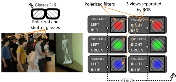
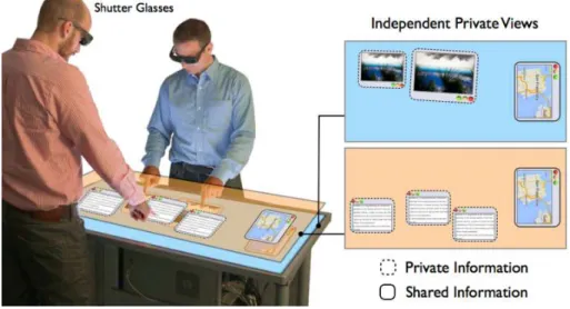
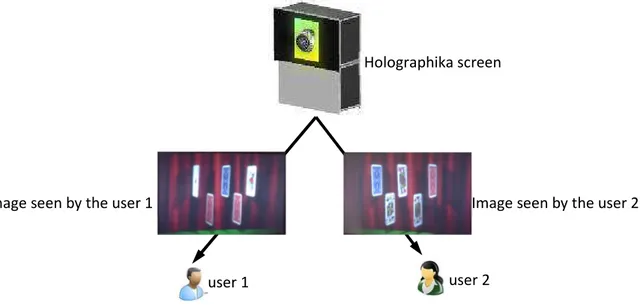
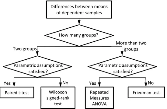
Figure 39 : High frequency project’s RGB is divided into 3 views, plus polarized filters, a multi-view system of 12 views is realized (Kulik et al., 2011). ___________________________________________________________ 55 Figure 40 : Two users can have private views on the same screen. They collaborate with private and shared views (Lissermann et al., 2014). _______________________________________________________________ 56 Figure 41 : Multiple users can view different 3D regions of interest independently. ______________________ 56 Figure 42 : 3D object can be seen from different positions in front of a screen. __________________________ 57 Figure 43 : three metaphors for rotating an object. ________________________________________________ 58 Figure 44 : Intersection of DMU, collaboration and CHI: Collaborative CHI through DMU _________________ 60 Figure 45 : One single CHI (right) replaces several CHIs (left). ________________________________________ 61 - Figure 46: Proposed scientific approach. ____________________________________________________ 63 Figure 47: Criteria of hypotheses and methods of evaluation ________________________________________ 66 Figure 48 Statistics analysis of the differences between means of dependent samples ___________________ 68 Figure 49 : Multi-user CHI platform consists multi-user CHI system and collaborative. ____________________ 71 Figure 50 : 3 images can be seen from different positions before a screen. _____________________________ 72 Figure 51 : Color filter-based multi-view glasses. __________________________________________________ 73 Figure 52 : Using polarized filters and two projectors, a multi-view system is realized. ____________________ 73 Figure 53 : Mechanism of a combination of a two-user 3D multi-view system. __________________________ 74 Figure 54 : Implementation of a combination of a two-user 3D multi-view system. ______________________ 74 Figure 55 : Technical schematic of tracking system and tracking hardware used. ________________________ 75 Figure 56 : Tracking system for two users _______________________________________________________ 76 Figure 57 : Calibration of tracking system. _______________________________________________________ 77 Figure 58 : Scheme of exchanging network ______________________________________________________ 77 Figure 59 : A complementary team game simulates an industrial case. ________________________________ 79 Figure 60 : Simulating game map and elements: 1st user, with blue glasses, can see only the mushrooms, and 2nd user, with red glasses, can see only the bombs. _______________________________________________ 80 Figure 61 : The player’s top view of maze is shown in (a). The player’s perspective is shown in (b); the helper’s top view of maze is shown in (c). The helper’s perspective is shown in (d). _____________________________ 81 Figure 62 : a) and c): user’s view of a cup in the car; b) and d): designer view of a cup in the car ____________ 82 Figure 63 : Designer view (a): A-pillar blocks a part of red street sign; Ergonomist view (b): A shadow covers the part of red street sign which can’t be seen by designer; Designer view (c): Designer adjusts the wheel;
Ergonomist view (d): Visible lower range line can show the intersection between designer’s FOV and the car. _ 83 Figure 64 : Multi-user CHI platform has various combinations of multi-user CHI systems and collaborative scenarios. _________________________________________________________________________________ 85 Figure 65 Experimental plan to validate the method. ______________________________________________ 87 Figure 66 : Experiment scheme of COLLAB_PACMAN simulation game ________________________________ 89 Figure 67 : Three experimental conditions, from left: multiple mono-user CHI systems (2Cs), multi-user CHI with subdivided views (1CSV), multi-user CHI with multi-view (1CMV). ____________________________________ 89 Figure 68 : Three experimental conditions. From left: multiple mono-user CHI systems (2Cs), multi-user CHI with subdivided views (1CSV), multi-user CHI with multi-view (1CMV). ____________________________________ 90 Figure 69 : Average and standard deviation of the measured variables: Time, Time_QnA. _________________ 92 Figure 70 : Average and standard deviation of the measured variables: Num_QnA. ______________________ 92 Figure 71 : Average and standard deviation of the measured variables: Time_QnA_dividedby_Time. ________ 93 Figure 72: Average and standard deviation of subjective criteria: involvement, learnability, satisfaction,
awareness, collaboration effort. _______________________________________________________________ 94 Figure 73 : Experiment scheme of COLLAB_MAZE_3D simulation game. _______________________________ 97 Figure 74 : Two experimental conditions: Left: multiple mono-user CHI systems condition; Right: multi-user CHI condition. _________________________________________________________________________________ 98 Figure 75 : Experiment conditions: Left: multiple mono-user CHI systems; Right: multi-user CHI. ____________ 99 Figure 76 : Average and standard deviation of subjective criteria: involvement, learnability, satisfaction, awareness, collaboration effort. ______________________________________________________________ 100
Figure 77 : Average and standard deviation of Finish time. _________________________________________ 102 Figure 78 : Left: average and standard deviation of player’s communication time in two conditions; Right: average and standard deviation of Helper’s communication time in two conditions _____________________ 102 Figure 79 : Left: average and standard deviation of the Ratio of player’s communication time to finish time; Right: Ratio of Helper’s communication time to finish time ________________________________________ 103 Figure 80 : Average and standard deviation of the Error committed between two multi-view condition and multiple mono-user CHI systems condition. _____________________________________________________ 103 Figure 81 : Experiment scheme of MUG collaborative design._______________________________________ 106 Figure 82 : User and designer during the experiment of MUG collaborative design. _____________________ 109 Figure 83 Score means of the variables in the quantitative questionnaire of the experiment. _____________ 110 Figure 84 Frequencies of the scores of variables in the quantitative questionnaire of the experiment. ______ 111 Figure 85 : Design of a project review of designer and ergonomist: A. a designer is driving a car in driver’s view; B. an ergonomist can see ergonomic data, e.g. height from shoulder to roof/ angle between head and arm, on user A in real time. _________________________________________________________________________ 114 Figure 86 : Experiment scheme of CAR ergonomic evaluation. ______________________________________ 115 Figure 87 : Designer and ergonomist verify the rear end of the front car. _____________________________ 117 Figure 88 : Validated hypotheses in the experimental plan: hypotheses are strong validated (in dark red); hypotheses are less strong validated (in light red); _______________________________________________ 119 Figure 89 : Scheme of evaluation of multi-user CHI. _______________________________________________ 123
List of Acronyms
BIM Building Information Modelling
CAD Computer Aided Design
CAE Computer Aided Engineering
CAM Computer Aided Manufacturing
CAVE Cave Automatic Virtual Environment
CE Concurrent Engineering
CFD Computational Fluid Dynamics
CHI Computer-Human Interface
CSCW Computer-Supported Cooperative Work
CVE Collaborative Virtual Environment
DMU Digital Mock-Up
FEA Finite Element Method
FMI Functional Mock-Up Interface
FOV Field of View
HCI Human Computer Interaction
HMD Head Mounted Display
HVS Human Visual System
IIVR Institut Image Virtual Reality
MVM Multi-View Mechanisms
PDM Product Data Management
PLM Product Lifecycle Management
POV Point of View
SE Sequential Engineering
VR Virtual Reality
VRPN Virtual Reality Peripheral Network WYSNWIS What You See Is Not What I See
17
Chapter I Introduction
Research context
Current industrial product lifecycle management (PLM) tools generally rely on the strategy of Concurrent Engineering (CE). Some of the product lifecycle stages are conducted in parallel and simultaneously and technical data on each stage are shared. Digital Mock-Up (DMU), the data set of all the technical data, has been used by various experts on different domains. Since the saved data has a variety of formats, e.g. the special format generated by domain-specific software, DMU stores multiple formats of data. Each expert work with one of the data representations of DMU. For communicating DMU data among its multiple representations, many works have been done to improve the interoperability among the engineering softwares and among the models in design activities.
Meanwhile, many creative tools have been developed to support these design activities. Though experts need to work together on the unique DMU, each expert has his/her own perspective of a specific representation of DMU’s technical data according to his/her expertise domain. An appropriate Computer-Human Interface (CHI) allows each expert to have a customized preference on the CHI: a proper visualization of representation of DMU and a proper manner to interact with DMU. Therefore, when multiple experts work collaboratively, the number of CHI increases as the number of experts. With the development of groupware and CHI technology, it is possible to devise more intuitive tools and methods to enhance the interoperability of collaboration among experts. CHI, which uses both multi-view and multi-interaction technologies, is applied by multiple experts when they work in co-located synchronous collaborative design activities. Our work is done in the context of research works belonged to the usability of CHI system for collaboration:
“How people work together in groups and how groupware CHI can support collaboration?”(Ishii et al., 1994)
Particularly, the question
“How experts work together through multi-user interface in complex multi-disciplinary product development?” (Kraemer and King, 1988; Tomiyama et al., 2009)
Research context of this thesis is described in I.1, followed by the statement of the scientific problem in I.2. A further exploration of the research questions is conducted in I.3. Lists of main contributions in general of this thesis are shown in I.4. A manuscript of the structure of the thesis is given in I.5.
Problems
Multi-disciplinary experts have trends to work collaboratively during product development. Sometimes they require a co-located real time working situation, such as project review and decision making. However, current technical support cannot provide efficient solutions to co-located real-time collaboration. The present problems of CHI systems are shown in following aspects:
18
- Multiple mono-user CHI systems are used. Each expert must work with his/her own CHI because of his/her specialty.
- The communication styles during collaborative work using current multiple mono-user CHI systems have negative impact on working efficiency.
- Using current multiple mono-user CHI systems causes a lower mutual awareness of collaboration between collaborators.
These problems are across several domains.
- A. Domain of collaborative engineering. It concerns the new strategies that are taken into consideration in Industrial Engineering. During a product lifecycle, how experts work collaboratively and what collaboration can bring to the product development needs to be discussed.
- B. Domain of Digital Mock-up. Multiple representations of data are contained in DMU. The interoperability of data exchanging with several industrial phases in multi-disciplinary product development needs to be discussed.
- C. Domain of Computer-Human Interface (CHI). Many CHI technologies can support multiple users. Their advantages and disadvantages need to be discussed. New technologies to support multi-representation collaborative work has been developed. The usability and efficiency need to be evaluated.
To sum up, our research approach is in the fields of collaboration, DMU and CHI. A collaborative working framework of multiple users considering all the domains above will be proposed later to this thesis. A new scene of collaborative working style considering industrial needs in product design will be created and verified. Thus, our approach from collaborative working condition is going to be evaluated both in academy and in industry.
Research question
There are technologies aiming at the creation of multiple user CHI system. According to different mechanisms, a taxonomy of multiple user CHI system will be summarized in our studies. Mainly, a multiple user CHI system is developed in both multi-view system and multi-interaction system. The issues we are facing for the multiple user CHI systems are as follows:
- How to design a multi-view system? - How to design a multi-interaction system?
Experts work with only one DMU during product development through a multiple user CHI system. Each expert can work with one representation of this DMU. Collaborating with each other, different experts can work together. Thus, the research issues for the behaviors of collaborators are:
- How’s experts’ working style when they are co-located? - How multi-user system can help collaboration?
To know if our approach really satisfies industrial case, the research issue for the evaluation is: - How to evaluate such collaborative work with multi-user CHI?
19
Considering all the research issues mentioned above, our research question to explore and to study in this thesis is as following:
“What is the influence of multi-user interface among users that work with different representations of a Digital Mock-Up during a collaborative work?”
Contributions
This thesis is in the context of industrial collaborative design. We describe the scientific context of several fields including CE, DMU, CHI. We then discuss the different approaches for displaying multiple representations of DMU and multiple interactions with DMU in the technical perspective. Aiming at exploring the influence of multi-user CHI on the collaborative work with several representations of DMU, we then carry out a series of work including technical developments, usage experiments and user experience evaluations.
This thesis was realized in collaboration with:
- Institute Image, one of research teams in the Laboratory of Electronics, Information, and Image (Le2i) which is a joined unit of University of Burgundy, Arts et Métiers and CNRS. Institute Image has also signed a framework agreement with the Renault’s Technical Centre for Simulation to form a joint public-private laboratory (lab LiV). The objective of Institute Image is the development of methods and tools for virtual immersion for engineer. Its missions are those of education, research, and development.
- The laboratory of product design and innovation (LCPI, EA 3927) is a research laboratory of Arts and Métiers ParisTech in Paris, whose work is part of the field of industrial engineering. The research theme of LCPI is optimizing the process of design and innovation. LCPI’s research activities benefit from both academic anchoring and a strong industrial partnership, which is an important vector for modernity and competitiveness. Based on the sciences of industrial engineering and Social & Human Sciences, LCPI has competences in: prototyping by virtual reality and rapid fabrication, innovation/foresight/creativity, analysis of the use, Kansei Engineering as well as eco-design and product lifecycle.
- Renault Technical Centre for Simulation, a competence center dedicated to the digital vehicle, based on virtual mock-up, and driving simulation tools. Its purpose is to benchmark advanced digital technologies and deploy relevant technologies inside Engineering departments. It has created a shared laboratory of LiV (Laboratoire d’immersion Virtuelle) with Institute Image, Arts et Métiers.
This thesis results in an important work with both scientific contributions and technical developments, including:
- A state of the art of collaborative computer human interface and multi-user technologies. - The development of a double user’s collaborative virtual reality working environment. - Two academic experiments of collaboration between two users with different roles with
different representations of a task using multi-view system
- Two industrial cases of collaborative work between different roles in design development, e.g. a product user and a product designer.
20
- The evaluation method of collaboration task with different representations. - Scientific publications
Manuscript structure
In this thesis, a general introduction of the PhD thesis is given in Chapter 1.
In Chapter 2, a state of the art is developed on the topic of collaboration, DMU and CHI, particularly the intersection of these research fields. The concept of user CHI with view and multi-interaction is described in detail.
In Chapter 3, several approaches to establish a multi-user collaborative CHI system are proposed, followed by the method for evaluating the multi-user collaboration system through academic experiment and industrial cases.
In Chapter 4, the two academic experiments and an industrial case are evaluated. Experimental data are analyzed and discussed.
In Chapter 5, we draw a conclusion of the thesis. A perspective of multi-user collaborative CHI across multi-representation of DMU in the future is discussed.
21
Chapter II State of the art
II.1
Introduction
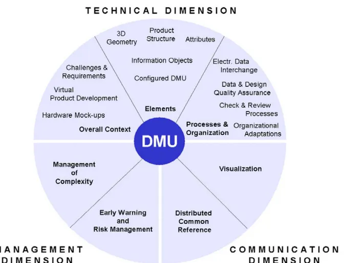
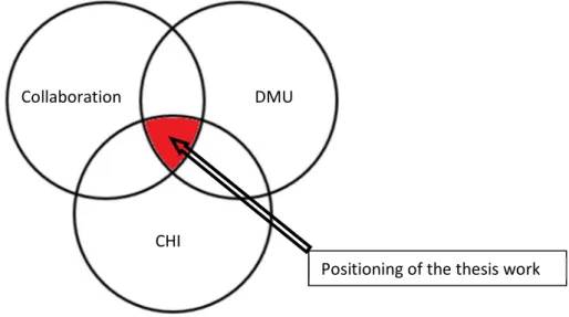
In this chapter, a state of the art across several domains is presented: Collaboration, Digital Mock-Up (DMU), and Computer Human Interface (CHI), as shown in Figure 1. These three areas and the intersections of them are discussed respectively in the state of the art. Collaboration is discussed in section II.2. We will describe the definition of collaboration in II.2.1, then the context of concurrent engineering in II.2.2. In II.2.3, collaboration working environments is explained, followed by the introduction of collaborative coupling styles.
Figure 1 : Three research areas: collaboration, DMU and CHI.
In II.3, a definition of Digital-Mock Up is firstly explored. The multi-representation of DMU is emphatically discussed. Multi-representation is a characteristic of DMU with which multiple users must break the barrier due to domain-specific expertise, as well as real time human communications. The interoperability of models and softwares are also discussed in II.3.3.
The state of the art of CHI starts with the definition and CHI modalities in II.4.1 and II.4.2. Then the difference between mono-user interface and multi-user interface is analyzed and discussed in II.4.3. Then the state of the art for multi-view visualization technology and multi-interaction technology is presented in II.4.4 and II.4.5. All the applications related to three research areas: collaboration, DMU, and CHI are categorized by the criterions which are proposed in II.5.
A synthesis of the state of the art and a positioning of the research question are given in II.6.
II.2
Collaboration
II.2.1
Definition
In this section, we focus on one of the three research areas: collaboration. The positioning of collaboration in the state of the art is highlighted in Figure 2.
Collaboration DMU
22
Figure 2 : The state of the art of collaboration which is one of the three research areas.
In general, collaboration is a process whereby two or more people or organizations join to do an intellectual work in accordance with common objectives. The early theory of collaboration can be traced back to a Game theory in applied mathematics and economics. When multiple players make decisions to maximize their returns, they should collaborate to find a solution with unanimous agreement. The early implementation of collaboration was primarily used in military industry. It is a private industry whose organization and cooperation were established among a nation’s armed forces. With the development in the theories of scientific management, in current industry, project management has been applied to different fields, including construction, engineering, and defense. The concept of collaborative work in project management refers to work that is no longer based on the traditional hierarchical organization, and more specifically a working mode where many people collaborate through information and communication technologies.
Over the years, in product management, the working mode has been evolving and changing. The theory of collaborative product management is updated towards economy and efficiency. We will discuss the recent collaborative working mode in product management in the next section.
II.2.2
Concurrent engineering
In industry, the product lifecycle management (PLM) is the process of managing backbone information of a product during different stages of the entire lifecycle, from product concept to exiting the market. In terms of methodology, PLM is also a supporting strategy for an enterprise that allows all the departments of this enterprise to share information and to control the business processes.
These departments usually include the activities of preliminary design, detailed design, physical simulation, ergonomic simulation, manufacturing, assembling, marketing, maintenance, design updating and optimization, destruction, and recycling. All these activities should be arranged in a proper way to ensure the lifecycle of a product.
The traditional Sequential Engineering (SE) is a product development method, which is known as “throwing it over the wall”. It focuses on developing a structured process with clearly defined and
Collaboration DMU
23
sequential phases of product plan, design, manufacturing and entering the market. Each one of these activities only starts when the one before has finished. This results in a lack of communication and understanding between the needs of different activities (Sage and Rouse, 2009), for example, a part is not well designed because it cannot be manufactured by current machine. This approach may increase the development time, increase the development cost, and lower the overall product quality (Smith and Eppinger, 1998).
Since several years, PLM has adopted the Concurrent Engineering (CE) process, which allows all the experts from different production activities to work collaboratively in parallel.
One of the widest known definitions of CE is the one given by the United States National Institute for Defense Analysis, which considers it to be “a systematic approach to the integrated, concurrent design of products and related processes, including manufacturing and support. This approach is intended to cause the developers to consider all elements of the product lifecycle from conception through disposal, including quality, cost, schedule, and user requirements.” (Valle and Vázquez-Bustelo, 2009).
Instead of the traditional sequential process of a product, CE is integrated product development method with which everyone involved works in parallel. CE allows some proper overlaps in the scale of time among several activities, as shown in Figure 3, if they are possible to be arranged in the same time. Even some of the activities will be better operated if they are conducted in the same time. Compared to sequential engineering, concurrent engineering allows overlaps of several activities in the scale of time. This saves time for the whole product lifecycle.
The goal of CE is to minimize single person work and to gain team collaboration. This may improve quality, reduce costs, and save time.
Figure 3 : Sequential engineering and concurrent engineering in product lifecycle. Product Design Process Design Product Planning Concept Development Commercial Production Product Planning Concept Development Commercial Production Product Design Process Design
Product Lifecycle Management (PLM)
Co nc ur re nt En gi ne er in g Se qu en tia l En gi ne er in g Time saving
24
Experts from different overlapped activities are now scheduled to work together. They can communicate, to have a result more than to repeat these activities. To improve the efficiency of their communication, they are now working collaboratively in parallel. From surveys of the companies who have implemented CE, we find that beyond a barrier of implementation of the management reluctance and resistance to change, CE brings companies obvious positive effects (Abdalla, 1999).
The benefits gained by companies implementing CE are illustrated in Figure 4. Shorter time to market (70%), better communication (59%), and better quality (56%) are direct reward of practicing CE. Reduction in repeatedly design changes are highlighted by almost 48% of companies surveyed. Reductions in testing, quality failures, and life-cycle cost are also achieved through the consideration of CE.
Figure 4 : Benefits gained during implementing CE (Abdalla, 1999).
For the companies which have different enterprise objectives and different characteristics of innovation process, they should prioritize their requests before selecting the most appropriate working style. CE leads to reductions in development time when it is used by companies who innovate in the product design or the production process. CE allows them to better meet the needs of specific market segments (Valle and Vázquez-Bustelo, 2009).
From the above, CE helps companies to quickly bring products to market at higher quality and less cost. Through integrated information technology tools, CE can support experts in product lifecycle, e.g. designers, to conduct development activities with latest changes, to share data with other parties involved in the product development process.
II.2.3
Collaboration working environment
In the theory of CE, product development activities may be arranged sometimes in a parallel way. Experts can work in a same time interval. Thus, collaboration is in need when they work together at the same time. The collaboration among experts would be realized only if they know the status of the product that every one of them is working on. They could catch up with others if they know and can keep change in real time (Mas et al., 2013).
25
To realize a collaborative working condition, special tools are in need to support experts from different activities. A concept of computer-supported cooperative work (Johansen, 1988) is proposed to research in supporting collaborative activities and their coordination by means of computer systems. Besides developing tools and techniques for group working, the psychological, social, and organizational effects of humans in collaborative activities are also being explored (Wobbrock et al., 2009).
Figure 5 : Collaborative work is separated into 4 conditions. (Agrawala et al., 1997).
From the technical perspective, this supporting system is considered as a groupware which has the mechanism of working collaboratively. According to space scale on the vertical axis of and time scale on horizontal axis (Figure 5), some typical groupware for collaborative activities are categorized. The collaboration can be co-located or geographically distributed in space. The single work of each person can be collaborative with others’ synchronously (same time) or asynchronously (different time). In the matrix of time scale and space scale, collaborative work is categorized into four main conditions:
- Face to face interaction (Same time/same place), - Continuous task (Different time/same place), - Remote interaction (Same time/different place),
- Communication plus Coordination (Different time/different place).
For each collaborative working condition, some typical supporting systems are shown on Figure 5. At same time, in some place, the main collaborative tools are decision room, wall display, and shared table. It concerns a physical face to face meeting among users. At same time, in different places, we often use the collaborative tools, such as video conference or telephone meeting. If people are collaborating at different time, in a same place, the tools used for collaboration are often paper tools for restoring files in a same information system, e.g. a file library, as well as product data management (PDM) which arranges the shifting of users on a same project. If people are working at different time,
Continuous task
Team rooms, large public display, shift work groupware, project
management, …
Communication + coordination Email. Bulletin boards, blogs, asynchronous conferencing, group
calendars, workflow, version control, wikis, … Face to face interactions
Decision rooms, single display groupware, shared table, wall
displays, room ware, …
Remote interactions Video conferencing, instance messaging, chats/Multi-User Dungeons/virtual worlds, shared
screens, multi-user editors, …
Time/Space Groupware Matrix Same time
synchronous Different time asynchronous
Sa m e pl ac e Co -lo ca te d D iff er en t p la ce re m ot e
26
in different places, the tools using Internet, Intranet are used, e.g. web storage, cloud computing, Google Sheet, especially the email, the most common tools used in collaborative work.
In this thesis, we focus on the same time/same place collaboration working environment as shown on Figure 5 during product development process. In a face-to-face interaction situation, people work collaboratively at a shared place. Firstly, they can use verbal communication, which is the most common type of interaction. Second, this group of people can use facial expressions to communicate and collaborate when they need discuss. This is more efficient than using remote communication voice method like a telephone (Agrawala et al., 1997). Besides, in face-to-face situation, the gestures of interaction are widely used because they bring an intuitive feeling of interaction. Face-to-face interaction collaborative working situation is very in common when people discuss. Nearly all the activities co-located and in real time are involved, including industrial applications, for example the collaborative work in product lifecycle.
During the product lifecycle, regular project reviews can strongly summarize the current work and assign the work of next stage by making modifications and proposing solutions to both strategies and technical details (Smith and Eppinger, 1998). Known as a part of collaborative design (Johansen, 1988), project review is often conducted by gathering experts in a same room, sharing information and making decisions. This working process needs collaboration among both the domain-specific software and the experts themselves. Thus, It is important to develop tools to support the project review process.
Figure 6 : Example of project reviews during product lifecycle (Fillatreau et al., 2013)
For example, Figure 6 shows how industrial companies intend to run project review checklists as many as possible during product lifecycle. The main development steps, and the associated project reviews(Fillatreau et al., 2013):
- the SGR (Specification Gate Review) is the requirements review; - the PGR (Preliminary Gate Review), is the preliminary design review; - the CGR (Critical Gate Review) is the detailed design review;
- the FEI (First Equipment Inspection) is the prototype review; - the IQA (Initial Quality Approval) is the industrialization review.
preliminary design PGR detailed design CGR virtual prototype production FEI virtual prototype production
IQA prototype physical validation FEI physical prototype production IQA Vi rt ua l Pr ot ot yp e Ph ys ic al Pr ot ot yp e requirements SGR
27
From these project review checklists, we find that industrial companies aim to use virtual numerical models of a product more often than a real prototype. Only the steps that cannot be performed without a physical prototype will involve a real prototype. The virtual numerical model, digital mock-up, will be discussed later in section II.3.
II.2.4
Collaboration coupling styles
As we discussed in last section, co-located synchronous collaboration is often applied in face to face working conditions. Many group activities, such as project review, which contains brainstorming, designing, discussing, and planning, involve co-located synchronous collaboration. Another characteristic of co-located synchronous collaboration is user’s transition between individual and shared tasks within a group. To describe a group activity, we introduce collaborative coupling. Collaborative coupling is defined as “the manner in which collaborators are involved and occupied with each other’s work” (Tang et al., 2006). This “coupling” implicates that collaborators’ activities are linked to one another. According to the different requirement of switching between independent and shared activity, collaborative coupling varies dynamically through the course of work from being very tight to very loose. When participants cannot do much work before having to simultaneously interact, the work is tightly coupled. Conversely, when participants can work independently for long periods of time, the work is loosely coupled.
Figure 7 : Collaboration styles which influenced how much information was shared among collaborators. Collaborators’ interactions are identified based on their data views and personal interactions. Eight different collaboration styles are shown on Figure 7: DISC: Active discussion about the data or task; VE: View engaged; SV: Sharing of the same view of a document or search result; SIDV: Sharing of the same information but using different views of the data; SSP: Work is shared to solve the same specific problem; SGP: Work on the same general problem but from different starting points; DP: Work on different problems, and hence different aspects of the task; D: Disengaged. As collaborators working on a data set, they adopt different collaboration styles. During a workflow, the collaborators present a fluid transition among coupling styles (Tuddenham and Robinson, 2009). E.g. at times, they discuss on the same problem (DISC), e.g. pointing to items, or scrolling in documents, even sharing a single document together (SV), e.g. look at the same document reader or the same search result list together at the same time; at other times, they would separate to work on different problems (DP), e.g. participants issued a search for "injure driver", one person is interested in the injured driver, the other searches for ambiguous event around a missile launch facility.
During the transition of collaboration styles, the percentage of common data and individual data in the amount of used data changes. In the coupling styles above SSP in Figure 7 (DICS, VE, SV, SIDV), sharing information is on the same problem, e.g. both read different documents from a shared set. Participants
VE
DISC SV SIDV SSP SGP DP D
Loose collaboration Close collaboration
28
issued a search for "injure driver", and then divided the results so each person read one half of the documents. Collaborators get common data from sharing information so that they can very well understand each other. In the coupling styles below SGP (DP, D), each collaborator gets his/her individual data because they work on different problems, e.g. participants issued a search for "injure driver", both participants search for docs to find information on a collision but start from different searches "accident" & "obituaries" and consider different sets of documents. In SSP and SGP working styles, people receive both common data and individual data. A transition of common and individual data means people must not only be focus on his/her own data but also try to understand his/her collaborator to complete a collaborative task.
In industry, the collaboration degree is also defined by the coupling style among decisions. These decision need a smart collaboration structure or a collaborative working environment to allow the distributed collaborative development activities (Segonds, 2011). The project manager, as well as the experts from different domains, their common data from sharing information to quickly reach an agreement. For the individual data, they must discuss, negotiate, and compromise to solve the problem.
Each expert adopts a special tool for his/her working domain. To support the collaboration across different product lifecycle stages, system tools are created to integrate all the individual tools. The conversion and recognition of common features across individual tools can simplify the design of the tools (Ma et al., 2008). We will discuss more about how to share information and how to construct system tools in the section II.3.
People have transitions among coupling styles. Common data and individual data alternate. However, in collaborative case, at the same time, more than one coupling styles can be used. Individual data from different problem, individual data from different starting of the same problem can be mixed with common data during the collaborative work. In this thesis, to simplify the category, we distinguish between three different coupling styles (Lissermann et al., 2014; Tuddenham and Robinson, 2009):
- Tight Coupling (Tight), sharing the same information;
- Loose Coupling (Loose), working on completely different problems;
- Mixed Coupling (Mixed), working on the other styles that has transition between common and individual data.
Coupling is primarily a reflection of collaborators’ need or desire to work closely or independently of one another. A collaborative sense making is then established among collaborators. Since the effect of collaboration is very subjective, the evaluation of collaboration is complex as well. In chapter III, we will discuss the evaluation method.
In this section, the definition of collaboration has been discussed and the collaborative working situations have been investigated in the process of product development. Co-located collaboration is widely used in the project review and decision-making phases during the product lifecycle. The coupling styles of collaboration have been discussed and categorized. A mixed coupling collaboration will be discussed in the next chapter considering the characteristic of Digital Mock-up.
29
II.3
Digital Mock-Up (DMU)
II.3.1
Definition
The positioning of the research area of this section in the state of the art is highlighted in Figure 8 . In this section, we focus on Digital Mock-up and its multiple representations. The need of multi-representation of DMU in early collaborative design and in the process of ergonomics evaluation is described in II.3.2.1 and II.3.2.2. The interoperability across multiple representation is discussed in II.3.3, followed by the introduction of the intersection of collaboration and DMU in II.3.4.
Figure 8 : The state of the art of DMU which is one of the three research areas.
A Mock-up is traditionally a hardware or physical model of a component, an assembly, or an entire product. It can be full-size or a scaled model made of paper, wood, metal, or actual production hardware (Leitner et al., 1994). The development of computer aided design (CAD) has essentially changed the way of developing a product in virtual model. And then more efficient development methodologies of CAD have been realized from the 2D to 3D. Meanwhile, the development of Product data management (PDM) has made an optimization of the product development processes to reduce time and cost during product lifecycle.
The establishment and development of virtual working environment and its data management benefit from the Digital Mock-up. The Digital Mock-up is defined as “a complete virtual product environment for the whole process of 3-dimensional development and maintenance of a complex product including configuration and change management” (Kaun, 2003).
Ideally, all participants in a PLM, such as a manager of the whole project, a department of one procedure, even an individual who oversees a specific task shall have the right to use the same PLM database and shall make contributions to this database.
Every product lifecycle activity of CE needs expert and domain-specific computer tools. These tools mainly contain the planning and management tools (PPS/ERP), the computer aided design (CAD) of the product, computer aided engineering (CAE) for physical analysis, computer aided manufacturing (CAM) for all operations of manufacturing and other software from different domains. Various experts use
Collaboration DMU
30
domain-specific software to produce various data (Pardessus, 2004). Each expert considers his/her own contribution to the product from one point-of-view (POV) of the whole product development according to his/her expertise. Then he/she shares his/her information with other experts by sending the data produced by the domain-specific software into a global database (Garbade and Dolezal, 2007) The large package of data itself, together with the product structure and attributes of this package of data builds up a Digital mock-up (DMU) in industrial engineering, as well as Building Information Modelling (BIM) model in architectural engineering (Segonds et al., 2012). BIM model is also a set of interacting policies, processes and technologies containing building design and project data in digital format throughout the building’s lifecycle.
Figure 9 : DMU is a virtual prototype which consists all the technical data of product characteristics (Dolezal, 2008)
From the definition of Digital mock-up, DMU is a virtual prototype of a product constructed before the physical prototype using manufacturing. In current industry, DMU is package of a product with digital technique data.
In addition to accurate geometrical database, a complete DMU also reflects the characteristics of the actual product, including appearance, complex structure analysis, kinematics and dynamics, the relationships between the assembly, tolerance, simulation information, human resources, materials, manufacturing resources, costs, and other information, shown in Figure 9. Through all aspects of DMU characteristics: analyzing, simulating and optimizing, we could repeatedly modify the design, transfer
31
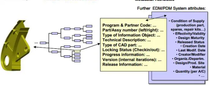
information, make decisions and ultimately get the optimal design solution (Kaun, 2003). These characteristics form additional metadata. Metadata of DMU consists in the Product Structure together with all attributes (Figure 10). Beginning from a preliminary Work Breakdown Structure (WBS) of a project, many PDM tools have been created to deal with the complex branch structures of a project tree. The Product Structure is a DMU metadata that defines the hierarchical dependencies of DMU models. It is a process of work breakdown and re-organization. The metadata of attributes identify 3D models and Product Structure elements in the DMU. The identification of models and the status of updating the models are recorded in these attributes in PDM tools (Dolezal, 2008).
Figure 10 : Relation between DMU’s geometry and metadata on a simplified example (Kaun, 2003).
II.3.2
Multi-representation
DMU offers data to every product lifecycle activity of CE according to the special needs of the expert and tools. DMU can represent data with different meaning and form a series of data in different data mode. E.g. an automobile sketch, an assembly of an automobile DMU, a point cloud format of an automobile in reverse engineering and a mesh model of this automobile DMU are all representations of DMU.
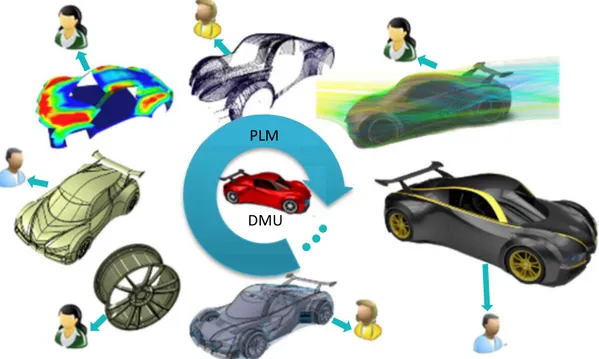
In Figure 11, DMU provides multiple representations to experts in a certain domain, such as a sketch, a single part, an assembly of a component or the whole car, CAE model for simulations, exterior design and a point cloud or mesh model for reverse engineering. On the contrary, from the experts point, how to get specific data depends on their special point-of-view of DMU. Every expert has his own point-of-view of the DMU.
Here the notion of “Representation” indicates that a given concept can be translated, in an equivalent manner, through different "models". Each of the "models" used matches a specific criterion in DMU. Considering only geometrical database in DMU, the geometry data of a model can be obtained through different "models”. According to user requirements in different development activities, such as project review and simulation, multiple representations of this model can be formed. E.g. mesh modelling, triangle modelling for graphic card, point cloud modelling, boundary representation (B-Rep) modelling, Constructive solid geometry (CSG) modelling, or simply the images of the model, if objective is to get
32
an identical object geometry as the user sees it. The same DMU can be also represented with different "models" (strength of material model, finite element model) to get an equivalent "representation" in the sense of mechanical strength. To extend, a "representation" could also coincide with an instantiation of a "model" participating to the definition of a product regarding special dataset and criterion (MG-IT, 1999).
Figure 11 : During entire PLM, multiple experts work with one unique DMU.
E.g. DMU can usually provide CAD tools geometry data for component interference examination, assembly process design, maintenance design, kinematics simulation; provide CAE tools mesh and constrain data for Finite element method (FEA) calculations preparation for the structural simulation or for Computational fluid dynamics (CFD) calculations in the aerodynamics and thermal simulations; provide CAM tools geometry and martial data for numerical manufacturing process management (Boussuge et al., 2012; Foucault et al., 2011).
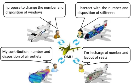
In industry, expert not only just cares about his own representation of DMU, he/she even has their preferred manner to interact with the DMU. Data goes both-way by inputting and outputting from DMU as shown in Figure 12. Both inputting and outputting have different manners according to the different domains of experts.
More precisely, experts from different domains use different tools e.g. software to deal with the data coming from DMU. Normally these tools cannot share data; experts will have difficulty in understanding the others’ data in the form of result. One expert is only expert in his field while not has the knowledge of all the corresponding fields. He/she is not interested in other expert’s field even cannot understand other expert’s concept and tolerance. This may cause his work less efficient with less communication and less cooperation and finally a possibility to rework.
In this thesis, the requirement of multi-representation of DMU is investigated in detail in two applied domains: Early collaborative design and Automotive ergonomic design, respectively corresponding to the two applications that we have developed in Chapter IV.
PLM
33
Figure 12 : Multiple experts work with multiple representations and interact with DMU using certain manners.
II.3.2.1 Multi-representation in Early collaborative design
Early stages of design, also called preliminary design, starts from the research of feasible concepts to first overall preliminary layout (Segonds et al., 2016).
Figure 13 : Framework describing the early stages of design process (Segonds, 2011).
According to two main product design methodologies, Pahl & Beitz (Beitz and Pahl, 1996) and Ullman (Ullman, 2002) , the first overall preliminary layouts describes the complete construction structure of the system or product being designed. First preliminary layout provides information about the advantages and disadvantages. The decision of the preliminary concept often leads the development of the future products. As shown in Figure 13, early stages of design are defined as all the activities from the “task” to achieve to the first preliminary layout.
During the early stages of design, every decision on the product engages most of the future development of design, production, assembly, maintenance, and disassembly. Thus, a collaborative design across the involved experts is in need. To share information among experts, the DMU of the preliminary product can be adopted by multiple users. Because of the characteristic of multi-representation, various models of the product are created. E.g. in Figure 14, various models used
DMU
I interact with the number and disposition of stiffeners
I propose to change the number and disposition of windows
My contribution: number and
disposition of air outlets I’m in charge of number and layout of seats
Needs translation and
interpretation
Concept search Design Product
validation Early stages of design
Preliminary Layout Task