HAL Id: pastel-00998311
https://pastel.archives-ouvertes.fr/pastel-00998311
Submitted on 1 Jun 2014HAL is a multi-disciplinary open access
archive for the deposit and dissemination of sci-entific research documents, whether they are pub-lished or not. The documents may come from teaching and research institutions in France or abroad, or from public or private research centers.
L’archive ouverte pluridisciplinaire HAL, est destinée au dépôt et à la diffusion de documents scientifiques de niveau recherche, publiés ou non, émanant des établissements d’enseignement et de recherche français ou étrangers, des laboratoires publics ou privés.
Synthèse et caractérisation thermodynamique
d’hydrates de gaz contenant de l’hydrogène
Amir Abbas Karimi
To cite this version:
Amir Abbas Karimi. Synthèse et caractérisation thermodynamique d’hydrates de gaz contenant de l’hydrogène. Génie chimique. Ecole Polytechnique X, 2013. Français. �pastel-00998311�
1
THÈSE
Pour obtenir le grade de
Docteur de l’École Polytechnique
Présentée et soutenue publiquement parAmir A. KARIMI
Le 22 novembre 2013
Synthèse et caractérisation thermodynamique
d’hydrates de gaz contenant de l’hydrogène
--- « Synthesis and thermodynamic characterisation
of gas hydrates containing hydrogen »
Directeur de thèse : Didier DALMAZZONE
Jury :
Bertrand Chazallon Rapporteur
Anthony Delahaye Rapporteur
Danièle Clausse Examinateur
Antonin Chapoy Examinateur
Jean Philippe Torre Examinateur
3
5
A
A
c
c
k
k
n
n
o
o
w
w
l
l
e
e
d
d
g
g
e
e
m
m
e
e
n
n
t
t
s
s
First and foremost I would like to thank my supervisor Didier Dalmazzone. It has been an honour to be his Ph.D. student. He has taught me, both consciously and unconsciously, how good experimental thermodynamics is. I appreciate all his contributions of time and ideas to make my Ph.D. experience productive and stimulating. Thank you Didier, not only because of what you have taught me, but also because of your kindness and your patience through these past three years!
The joy and enthusiasm Didier has for his research was contagious and motivational for me, even during tough times in the Ph.D. pursuit. I am also thankful for the excellent example he has provided as a successful researcher and professor.
I would also like to thank the director of our laboratory Walter Fürst, for giving me the opportunity to realize my research at the best possible condition under his direction.
Collective and individual acknowledgements are conveyed to my thesis reading committee members. I am grateful to my thesis referees Dr. Antonin Chapoy and Dr. Antony Delahaye for accepting this role and reading the thesis manuscript with great care, interest and patience. It was an extreme honor for me to have them as well as other members of the jury, Dr. Danièle Clausse, Dr. Bertrand Chazallon and Dr. Jean Philippe Torre as my thesis board of examiners.
This thesis was funded by École Polytechnique de Paris, and I would like to thank both École
Polytechnique and ENSTA for their generous support. Both
schools have provided me a rich and fertile environment to study and explore new ideas. At École Polytechnique I would like to thank all the members of Graduate School (EDX) and the administration staff. At ENSTA, the members of the UCP (Unité de Chimie et Procédés) have contributed immensely to my personal and professional time. The group has been a source of friendships as well as good advice and collaboration. I am especially grateful to Alain Gaunand, Patrice Paricaud, Laurent Catoire, Henri Planche and I would like to specially thank Elise Provost and Johnny Deschamps for their help and technical support during my thesis. I would like to acknowledge Oleksandr Doltko post-doc researcher who was here on the first year of my PhD. We worked together on H2-TBPBH4 system, and I very much appreciated his
6
My time at ENSTA was made enjoyable in large part thanks to my many friends that became a part of my life. I am grateful for time spent with my friends, for making one of the most pleasant periods of my life, to Julien Glorian (Ju) my office mate and my French teacher at the same time! (vocabulary & pronunciation) Mickael Matrat (Mickey) again my French teacher focusing on grammar & writing, Aurélien Demenay (DéDé), Elodie Fazer, Kodjo Coudoro (The last king of Togo), Jean-Baptiste May-Carle (JB), Karl Chatelain (Karlito) and also to my Asian friends Zhewei Yu (JiJi), Ayako Fukumoto and Wei Lin.
I would like to express my gratitude to a group of my best friends outside UCP, starting with Behzad Nazer who has always been like a brother for me, the very old friend Mohsen Laali, fascinating Bora Erdamar (Boracim) who opened new horizons in my personal life and way of thinking, my very kind friend and former neighbour Robert Somogyi, very supportive Susan Memari for whom I wish all the best, and special thanks to Yassaman Sarabi a very compassionate and everlasting friend of mine.
I gratefully acknowledge the unforgettable support of Nastaran Manoucheri specially in the first days and months of my arrival to France. I would like to thank Dr. Amir Mohammadi at École des Mines de Paris and all the other Iranian friends of mine in France.
Last but not least, I would like to thank my family for all their love and encouragement. For my parents who raised me with love and supported me in all my pursuits. For my sister who has been my best friend all my life and I love her dearly and thank her for all her advice and support. For the presence of my aunt and his kind husband in Paris, for all their loving and encouraging support. Thank you.
7
TABLE OF CONTENTS
L
Liissttooffaabbbbrreevviiaattiioonnaannddssyymmbboollss ... 9
L LiissttooffFFiigguurreess: ... Erreur ! Signet non défini.1: Contexte et Objectifs et L’étude ... 15
Introduction ... 17
C ChhaapptteerrOOnnee: :IInnttrroodduuccttiioonnoonnhhyyddrrooggeennssttoorraaggee ... 19
1.1. Introduction ... 21
1.2. Chemical & physical properties ... 23
1.3. Industrial applications of hydrogen ... 27
1.3.1. Hydrogen as a reactant ... 27
1.3.2. Hydrogen as oxygen scavenger ... 28
1.3.3. Hydrogen as a fuel ... 28
1.4. Hydrogen storage methods ... 28
1.4.1. Gaseous storage (Compression) ... 29
1.4.2. Liquid storage (Liquefaction) ... 31
1.4.3 Physical adsorption of hydrogen in porous materials ... 33
1.4.4. Metal hydrides and complex hydrides (Chemisorption) ... 36
1.5. Clathrate hydrates ... 38
1.5.1. Introduction ... 38
1.5.2. Water and Ice (irregular) properties ... 39
1.5.3. Structures of different hydrate types ... 40
1.5.4. Hydrogen storage in inclusion compounds ... 46
1.5.6. Conclusion... 56
C Chhaapptteerrttwwoo: :EExxppeerriimmeennttaallmmeeaassuurreemmeennttss ... 57
2.1. Introduction ... 59
2.2. Differential Scanning Calorimeter (DSC) ... 59
2.2.1. Heat flux differential scanning calorimeters ... 61
2.2.2. Power compensating differential scanning calorimeters ... 62
2.2.3. Calorimetric signals ... 63
2.2.4. DSC principle ... 65
2.2.5. Measurement of phase transition temperature ... 69
8
2.3. Isochoric reactor ... 75
2.3.1. Description ... 75
2.3.2. Experimental procedure ... 76
2.4. Gas phase composition analysis : Gas Chromatography ... 79
2.5. Liquid phase analysis : Atomic Absorption Spectrometry ... 81
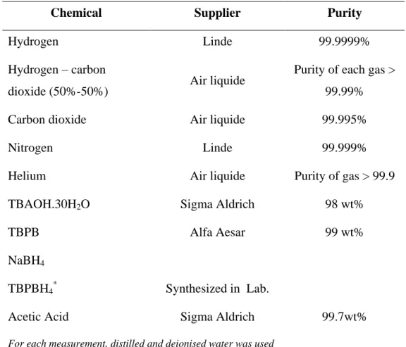
2.6. Materials ... 81
C Chhaapptteerrtthhrreeee: :RReessuullttss&&DDiissccuussssiioonnss11((SSeemmii--ccllaatthhrraatteessyysstteemmss)) ... 85
3.1. Investigation of TBPBH4 semi-clathrate system ... 87
3.1.1. Introduction ... 87
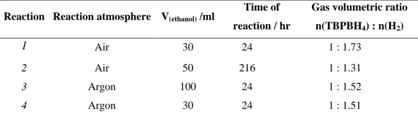
3.1.2. Investigations of the synthesized TBPBH4 salt ... 88
3.1.3. Investigations of TBPBH4– H2O system ... 90
3.1.4. Investigation of the H2-TBPBH4– H2O system ... 93
3.1.5. Investigation of the N2 -TBPBH4– H2O system ... 97
3.2. Investigation of TBAOH semi-clathrate... 99
3.2.1. Introduction ... 99
3.2.2. Investigation of TBAOH – H2O system ... 99
3.2.3. Investigation of the H2– TBAOH – H2O system ... 103
3.2.4. p-V-T measurements and hydrogen storage capacity ... 106
C Chhaapptteerrffoouurr: :RReessuullttss&&DDiissccuussssiioonnss22((CCllaatthhrraatteessyysstteemmss)) ... 109
4.1. Propane + Hydrogen + Water ternary system ... 111
4.1.1. Introduction ... 111
4.1.2. Pure Propane – H2O system ... 112
4.1.3. Hydrogen + Propane + Water system ... 121
4.2. Carbon dioxide – Hydrogen system ... 128
4.2.1. Introduction ... 128
4.2.2. A discussion on the phase diagram of H2-CO2-H2O ... 128
4.2.3. Investigation of H2-CO2-H2O phase equilibrium ... 132
4.2.4. Composition analysis of CO2-H2O hydrate ... 134
C
Coonncclluussiioonnssaannddppeerrssppeeccttiivvees ... 137s R
9
L
LIISSTTOOFFAABBBBRREEVVIIAATTIIOONNAANNDDSSYYMMBBOOLLSS
Abbreviations
C Molar concentration mol . m-3
CS Heat capacity of sample J . K-1 . kg-1
CR Heat capacity of reference J . K-1 . kg-1
CNG Compressed Natural Gas
DOE United states‟ Department Of Energy
DSC Differential Scanning Calorimeter
G Gas phase
GC Gas Chromatography
H Hydrate phase
h Molar enthalpy J . mol -1
hyd Hydrate structure
Ih Hexagonal ice
K Heat transfer coefficient
L/ Liq. Liquid phase
LNG Liquefied Natural Gas
M Molar mass kg . mol-1
MOF Metal Organic Framework
n Mole number mol
P Pressure Pa
q Molar heat flow J . mol -1
R Thermal Resistance
S Molar entropy J . K-1. mol -1
T Temperature K
TBAB Tetra-butyl-ammonium bromide
TBABh Tetra-butyl-ammonium brohydride
TBACl Tetra-butyl-ammonium chloride
TBAF Tetra-butyl-ammonium fluoride
TBAOH Tetra-butyl-ammonium hydroxide
TBPBH4 Tetra-butyl-phosphonium brohydride
THF Tetrahydrofuran
10
V Vapour phase
wis Isothermal work J . mol -1
Z Compressibility factor
Greek Letters
γ Thermal conductivity W . K -1 m -1
µjT Joule-Thompson coefficient K . Pa -1
ρ Density Kg . m -3
φ Heat flow rate J . mol-1 . s-1
Subscripts 0 Initial A Aqueous phase eq Equilibrium sate F Furnace H Hydrate phase HC Hydrocarbon L Liquid phase R Reference S Sample V Vapour W water Constants
11
L
LIISSTTOOFFFFIIGGUURREESS::
Figure 1 – Compressibility factor (Z) of hydrogen ... 24
Figure 2 – Phase diagram of Hydrogen[2] ... 32
Figure 3 – Comparison of the gravimetric energy densities of pure stored hydrogen with other energy sources [2] ... 33
Figure 4 – Single crystal structure x-ray of MOF-5. Eight metal clusters each containing four ZnO4 tetrahedral nodes, make a enclosed large cavity for entrapping hydrogen molecules. Reprinted from [18]. ... 36
Figure 5 - Hydrogen bond in water molecule: a) between two molecules b) between four molecules [30] ... 39
Figure 6 - Crystal structure of ice Ih [30] ... 40
Figure 7 - Five different gas hydrate cavities rates: (a) pentagonal dodecahedron (512), (b) Tetrakaidecahedron (51262), (c) hexakaidecahedron (51264), (d) irregular dodecahedron (435663), and (e) icosahedron (51268) [30] ... 41
Figure 8 - View of structure I of hydrate clathrate. a) five 512 polyhedral are connected by two 51262 polyhedral b) two-dimensional view of sI [3] ... 43
Figure 9 - Schematic of hydrate structure II [30] ... 44
Figure 10 - Schematic presentation of hydrate structure H [30] ... 44
Figure 11 - Guest size relationship with hydrate type [30] ... 46
Figure 12 - The cage occupancy proposed by Mao al.[10] : A) 4 H2 molecules occupy hexakaidecahedron (51264) cavities B) 2 H2 molecules occupy pentagonal (512) cavities ... 47
Figure 13 - Schematic structure of TBAB hydrate crystal [55] ... 52
Figure 14 - TBAB semi-clathrate hydrate, type A and B [58] ... 53
Figure 15 - The structure around the tetra-n-butylammonium cation, located at the centre of four cages [53] ... 54
Figure 16 - Disk type DSC [66] ... 61
Figure 17 - Cylinder type DSC [66] ... 62
Figure 18 - Power compensating DSC [66] ... 63
Figure 19 - Schematic presentation of temperature evolution in a DSC [69] ... 64
Figure 20 – Schematic illustration of DSC cells, TR : reference temperature, CR : heat capacity of reference, TS : sample temperature, CS : heat capacity of sample, TF: furnace temperature [70] ... 66
Figure 21 - Example of a heat-flux curve for calculation thermal resistance, R and the phase transition temperature ... 71
Figure 22 - A schematic presentation of HP-µ DSC VII (SETARAM) ... 73
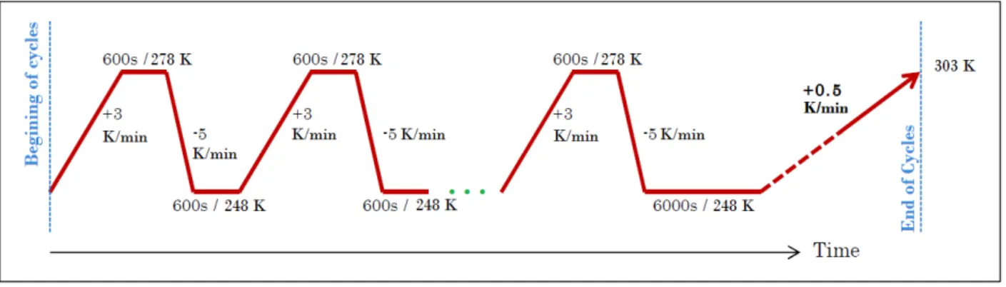
Figure 23 - A schematic presentation of multi-cycle thermal program for hydrate formation ending with hydrate dissociation. ... 74
Figure 24 - Thermal cycling for a CO2-H2-H2O system at 14 MPa (equimolar gas composition) ... 75 Figure 25 - Schematic of hydrate cell (with courtesy of Ecole des Mines de Paris, CEP/TEP). DAU, data acquisition unit; DW; EC, equilibrium cell; G, gas cylinder; GC, gas
12
chromatograph; HPT, high pressure transducer; LB, liquid bath; LPT, low pressure
transducer; ... 76
Figure 26 - A schematic T-P diagram of hydrate ... 77
Figure 27 - The ROLSI sampler connected to the reactor ... 80
Figure 28- The H1 NMR spectra of the TBPBH4 compound ... 89
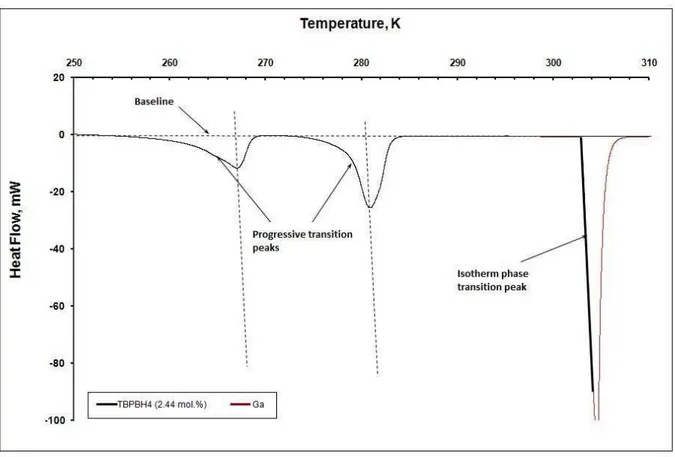
Figure 29 - DSC heat flux curve for the dissociation of 2.44 mol% of TBPBH4 ... 90
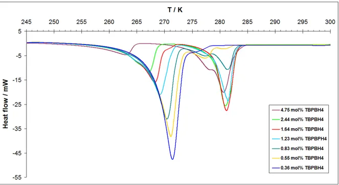
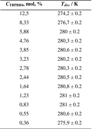
Figure 30 - DSC heat flux curve for TBPBPH4 hydrates under ambient pressure in a salt concentration range of 0.36 to 4.75 mol% ... 91
Figure 31 - The phase diagram of the TBPBH4 + H2O binary system in the region of crystallization of high water content semi-clathrate polyhydrate. (Dashed lines – equilibrium behaviours can vary. Solid line – data more clear). ... 93
Figure 32 - DSC heat flux curve of the 1.96 mol% solution of TBPBH4 under different hydrogen pressures ... 94
Figure 33 – P-T data for additive + water + H2 systems. (The type of additive, its concentration and the source of data are presented on the diagram. Error bars represent the uncertainties on phase change temperatures, based on repeated determinations of melting points of gallium. Lines represent exponential fits of experimental points) ... 95
Figure 34 – Effect of pressure on TBPBH4 clathrate of different salt concentrations ... 96
Figure 35 - P-T phase diagram of additive+water+N2 system ... 98
Figure 36 - Comparison of hydrogen and nitrogen pressure on the phase diagram of TBPBH4 ... 98
Figure 37 - DSC heat flux curve of dissociation of 1.23 mol% solution of TBAOH ... 100
Figure 38 –Heat flux curve of TBAOH hydrate in different salt concentration at ambient pressure ... 101
Figure 39 - The phase diagram of TBAOH-H2O binary system ... 102
Figure 40 - The heat flux curve of 1.23 mol% TBAOH hydrate at different hydrogen pressures ... 103
Figure 41 - Effect of hydrogen pressure on dissociation temperature of the second hydrate structure of TBAOH-H2O system (hyd2) ... 104
Figure 42 - Effect of hydrogen pressure on dissociation temperature of the first hydrate structure of TBAOH-H2O system (hyd1) ... 105
Figure 43 – comaprison of P-T equilibrium data of various H2+semi-clathrate hydrates .... 106
Figure 44 - p-V-T measurement of a 1.41 mol% solution of TBAOH under 10 MPa hydrogen [The dot lines in this diagram are just extrapolating of the data and they do not present confirmed measurements] ... 107
Figure 45 – Comparison of specific energy of propane with different common fuels ... 111
Figure 46- P-T diagrams for hydrocarbon+water systems with higher quadruple points [30] ... 113
Figure 47 - DSC heat flux curve of propane-water system at 0.6 MPa (30 cycles) ... 115
Figure 48 - DSC heat flux curve of propane-water system at 0.3 MPa (3 cycles) ... 116
Figure 49 - DSC heat flux curve of dissociation of propane hydrate at 0.51 MPa ... 116
13
Figure 51 - P-T diagram of propane hydrate formation dissociation at 0.46 MPa obtained by
p-V-T measurements ... 118
Figure 52 - The phase diagram of propane + water system ... 121
Figure 53 - Hydrate formation conditions for hydrogen + propane hydrate [92] ... 122
Figure 54 - Decomposition curve of propane + hydrogen propane double clathrate hydrates. h1: cubic structure II of pure propane hydrate, h2: propane hydrate with an unknown structure [91] ... 122
Figure 55 - Phase envelope of the system Hydrogen + Propane ... 123
Figure 56 - Phase diagram of natural gas with a composition of methane: 70.85 mol%, ethane 11.34 mol%, propane: 6.99 mol%, isobutane 3.56 mol%, and n-butane: 4.39 mol% and carbon dioxide: 2.87 mol% [31] ... 124
Figure 57 - DSC heat flux curves of the 1 mol% fraction of propane in the propane + hydrogen - water system under pressure of 5 MPa ... 125
Figure 58 - P-T phase diagram of Propane + Hydrogen - Water system under different pressures for different component compositions ... 126
Figure 59 - Clapeyron equation presentation of Propane - Hydrogen hydrate dissociation . 127 Figure 60 - DSC heat flux curve for H2-CO2-H2O system at pressure of 4 MPa ... 130
Figure 61 - Schematic presentation of P-T phase diagram of CO2-H2O system [30] ... 131
Figure 62 - DSC heat flow curve of H2-CO2-H2O system under pressure of 7 MPa ... 131
Figure 63 - Comparison of equilibrium data of CO2, H2 and H2-CO2 system ... 133
Figure 64 - Comparison of equilibrium data of CO2, H2 and partial pressure of CO2 in the H2 -CO2 system ... 133
14
L
LIISSTTOOFFTTAABBLLEESS::
Table 1 - The comparison of the heating values, and CO2 emission of common fuels with
hydrogen _________________________________________________________________ 21 Table 2 - Comparative data on vapor and liquid densities of hydrogen, methane and gasoline _________________________________________________________________________ 25 Table 3 - Hydrogen Properties [2] ______________________________________________ 26 Table 4 - Characteristics of commercial hydrogen storage containers [2] _______________ 30 Table 5 - Comparative hydrogen storage data of most common complex hydrides ________ 38 Table 6 - Geometry of hydrate cages ___________________________________________ 45 Table 7 - Summarized table of hydrogen clathrates data ____________________________ 56 Table 8 - Thermal conductivity of common career gases ____________________________ 80 Table 9 - Polynomial parameters of calibration curves ______________________________ 81 Table 10 - Chemicals used in the measurements, with their purities and their suppliers ____ 82 Table 11 - Results of the gas volumetric analysis of the TBPBH4, synthesized at different
conditions ________________________________________________________________ 89 Table 12 - Dissociation temperatures of TBPBH4 hydrates as a function of the salt
concentration. _____________________________________________________________ 92 Table 13 - Temperatures of dissociation of the G + TBPBH4 semiclathrate hydrate at different
gas pressures (G = H2 or N2) __________________________________________________ 94
Table 14 – Dissociation temperature of TBPBH4 semiclthrates under different hydrogen pressures _________________________________________________________________ 96 Table 15 - Dissociation temperature of TBPBH4 hydrates as a function of concentration in
different pressures of N2 _____________________________________________________ 97
Table 16 - Properties of TBAOH hydrate structures ________________________________ 99 Table 17 - Temperatures of (Ice + hyd2) eutectic melting, TE, (hyd1 + hyd2) peritectic
melting, TP, and hyd2 dissociation,Tdiss, in the system H2O + TBAOH at variable salt concentrations ____________________________________________________________ 101 Table 18 - Dissociation temperatures of H2-TBAOH-H2O semi-clathrates under different hydrogen pressures ________________________________________________________ 104 Table 19-Hydrogen storage capacity of common hydrates and their formation conditions _ 108 Table 20- Critical point of some hydrate forming gases with respect to the triple point of water ___________________________________________________________________ 113 Table 21- Second quadruple point (Q2) of Propane-water system ____________________ 114
Table 22 - Experimental data of dissociation temperature of propane hydrate___________ 119 Table 23 - The dissociation temperatures of propane + hydrogen hydrates as a function of gas composition and pressure ___________________________________________________ 126 Table 24 - Phase equilibrium data of pure carbon dioxide hydrate and pure hydrogen hydrate ________________________________________________________________________ 129 Table 25 - Phase Equilibruia data of H2-CO2-H2O system __________________________ 132
15
Contexte et Objectifs et L’étude
Dans la perspective de la transition vers de nouvelles sources énergétiques, l’hydrogène apparaît comme un vecteur d’énergie prometteur. L’hydrogène est doté d’excellentes propriétés physico-chimiques qui en font un combustible d’avenir : il constitue une énergie propre, renouvelable, avec un pouvoir calorifique trois fois supérieur à celui de l’essence. Mais les difficultés liées au stockage et au transport de l’hydrogène restent des obstacles majeurs au développement d’une économie de l’hydrogène comme vecteur énergétique.
Dans ce contexte, la présente étude concerne la synthèse et la caractérisation d’hydrates d’hydrogène du type clathrate et semi-clathrates par analyse calorimétrique différentielle sous haute pression (40 MPa) et en réacteur isochorique pour les mesures volumétriques.
Dans un premier temps, une famille particulière de semi-clathrates qui se forment à partir d’eau et de gaz en présence de sels d’ammonium (TBAOH) ou de phosphonium quaternaires (TBPBH4) a été
étudiée. Nous présentons dans cette partie une étude du comportement des systèmes TBAOH-H2-H2O,
TBPBH4 -H2 -H2O etTBPBH4 - N2 -H2O, leurs diagrammes de phases isobares (x, T) et une étude
volumétrique de la quantité de gaz stocké.
Dans un deuxième temps, le concept de Tuning a été développé dans un mélange de H2-C3H8 afin
d’étudier son impact sur la stabilité de l’hydrate d’hydrogène. Enfin, la séparation de l’hydrogène dans un mélange équimolaire de CO2-H2 par cristallisation d’hydrate a été étudiée et l’analyse des
compostions initiale et finale du mélange de gaz réalisée.
Mots clé: Hydrates de H2, hydrates semi-clathrates, équilibre de phase, analyse calorimétrique
17
Introduction
The limited supply of fossil fuels and the environmental issues they provoke make shifting towards clean and renewable energy sources inevitable. In this perspective, hydrogen as a clean energy career is attracting more and more attention. Hydrogen is a clean fuel which its combustion does not produce any pollutant or any greenhouse gas. Moreover, its energetic density is around three times higher than those of conventional fuels [1]. In spite of its favourable chemical properties, storage and transport of hydrogen has always been a challenge for industry. In this regard, different technologies were proposed from hydrogen compression and liquefaction, to hydrogen adsorption in carbon nanotubes and metal organic frameworks.
Any proposed method for industrial storage of hydrogen must cover two criteria: Firstly, the mass density of the stored hydrogen must meet the economic/industrial requirements and secondly the energy consumption of the storage method itself must not exceed the energy content of stored hydrogen. Respecting these two criteria, clathrate hydrates have been studied as a potential storage medium for hydrogen.
Clathrate hydrates are inclusion compounds made up of water and a guest molecule. They are formed by insertion of gas molecules into cavities formed by water molecules arranged in polyhedral patterns, under low temperatures and relatively high gas pressures. Hydrate dissociation and formation conditions depend principally on the nature of the crystalline structure, size of the guest molecule, gas pressure and the molecular interaction between guest molecules and hydrate structure. In order to reduce the severe hydrate formation conditions, usually some additives are added. These additives are usually organic salts or constituents of natural gas.
This work comprises synthesis and characterization of hydrogen hydrates of different structures in presence of water soluble additives and gas promoters. At the first step, the phase equilibria of semi-clathrate systems made in presence of an ammonium quaternary salt (TBAOH) and a phosphonium quaternary salt (TBPBH4) were investigated. Using a differential scanning calorimeter (DSC) the
equilibrium dissociation temperatures of these semi-calthrates were measured under different hydrogen pressures. Their phase diagrams were established and the effect of hydrogen pressure upon their stability was studied. Moreover, using an isochoric high pressure reactor the quantity of hydrogen stored in these semi-clathrates was investigated.
In the second part, effect of a promoter gas such as propane on the stability of hydrogen hydrate was investigated. These investigations were preceded by independent measurements of pure propane hydrate which were followed on the hydrogen + propane mixture of 1 mol%, 3 mol %, 5 mol% and 10 mol% of propane. The effect of the composition and total gas pressure was investigated using DSC.
The last system studied was the clathrate hydrates formed in the CO2-H2 gas mixture. The phase
equilibrium of the system was studied and compared with the literature data of pure CO2 hydrate and
pure H2 hydrate. The tendency of both components in occupying hydrate cavities was investigated by
analyzing the initial (before hydrate formation) and final (after hydrate formation) gas composition.
The first chapter of this dissertation is a bibliographic review of hydrogen’s industrial applications and storage technologies. The second chapter describes the experimental techniques that were used
18
during the thesis. In the third and fourth chapters, the results obtained in the presence of saline and gas additives are presented and discussed, respectively.
19
C
C
h
h
a
a
p
p
t
t
e
e
r
r
O
O
n
n
e
e
:
:
I
I
n
n
t
t
r
r
o
o
d
d
u
u
c
c
t
t
i
i
o
o
n
n
o
o
n
n
h
h
y
y
d
d
r
r
o
o
g
g
e
e
n
n
s
s
t
t
o
o
r
r
a
a
g
g
e
e
This chapter comprises the physical and chemical properties of hydrogen as an energy source as well as different hydrogen production methods in industry and its application in different industrial sectors.
Respecting the main objective of this research on hydrogen storage, common known hydrogen storage methods are presented and are described here and finally, clathrates hydrates are introduced as a potential for gas storage. This chapter terminates by a literature review on the history of hydrates, their properties, structure, formation / dissociation conditions are given.
21
1.1. Introduction
Hydrogen as an environmentally clean and efficient energy carrier is attracting more and more attention worldwide. Study of fuel evolution history demonstrates a general trend in the increase of hydrogen content of fossil fuels from coal to petroleum oil and then to natural gas. This trend of increase of hydrogen content may finally reach the consumption of pure hydrogen; therefore it is not far from imagination if hydrogen is called the fuel of the future. At ambient conditions, hydrogen is a colourless and odourless nontoxic gas. It has the lowest density among all the elements and after helium it has the lowest melting and boiling temperatures. Hydrogen has a high diffusion coefficient and a high heat capacity. Due to its single valence electron, it is a highly reactive and flammable gas, producing a great amount of energy which is at least three times more than the average value of liquid hydrocarbons [Table 1].
Table 1 - Comparison of heating values and CO2 emission of common fuels and H2 [1] Fuel Heating value (kJ/g) Chemical Formula kg[CO2] / L
Propane 50.4 C3H8 1.55 Ethanol 29.7 C2H5OH 1.55 Gasoline 46.5 C7H16 2.39 Diesel 45.8 C12H26 2.63 Biodiesel 39.6 C18H32O2 2.27 Methane 55.8 CH4 0.35 Oil 47.9 C14H30 2.39 Wood 14.9 - 1.07 Coal 30.2 - 2.27 Hydrogen 141.9 H2 0
Hydrogen is considered as a clean energy source because its combustion does not produce pollutant reaction. Its combustion in internal combustion engines produces low pollution and even no pollution in fuel cell engines. The combustion of hydrogen with oxygen produces water as its only product:
22
Equation (1)
The enthalpy of this reaction is ΔRH= -242 MJ·kmol-1. If the water condenses in this reaction,
the enthalpy of condensation will be added to the total enthalpy of reaction making ΔRH= -285
MJ·kmol-1 and giving a heating value (the gross calorific value) of Ho=142 MJ·kg-1 [2].
Due to the high temperature of hydrogen combustion some nitrogen molecules in the air may react with the oxygen molecules and produce nitrogen oxides (NOX).
Equation (2)
In addition to the nitrogen oxides, some traces of carbon oxides may also be produced originating from the oil used in the combustion chamber.
Source of hydrogen:
Although hydrogen is the most abundant element on the earth, only less than 1% of it exist in the form of molecular hydrogen gas (H2) [3]. Hydrogen can form chemical compounds
(hydrides) with most of the elements. Due to its ability to combine with carbon to make long chains, it plays an important role in organic life. The major source of hydrogen in nature is water in which hydrogen molecules are chemically bond to oxygen molecules and can be released either by electrolysis of water or thermal dissociation of H2O molecules. But from
about 5 . 1010 kg of the hydrogen consumed each year worldwide, hydrogen is to a large extent produced from steam reforming of natural gas at high temperatures (973-1373K) [3]. This reaction can be summarized as:
Equation (3) The product mixture is known as synthesis gas. Using the excess of water stream, through a reaction called water shift reaction, CO molecules convert into CO2. This reaction is also the
industrial process for production of carbon dioxide:
Equation (4) Production of hydrogen in this way bears a manufacture cost about three times higher than petroleum products [3]. Therefore, any proposed method for storage of hydrogen must avoid imposing considerable operational costs.
23
1.2. Chemical & physical properties
Producing, storing and consuming hydrogen is not possible without knowing its physical and chemical properties. In this part a summary of important properties of hydrogen related to its storage process is presented. A more detailed list of hydrogen‟s physical and chemical properties are gathered and presented in Table 3.
Thermodynamic equation of state:
Hydrogen as well as all the other pure substances can exist under vapour, liquid and solid phases. Like all the pure substances the thermodynamic state of hydrogen can be defined by knowing two independent intensive state variables. At ambient pressure hydrogen is in the gas form and obeys the ideal gas equation of state:
Equation (5)
In which:
v [m3·mol-1]: molar volume
R = 8.31472 [J·mol-1·K-1]: Universal gas constant
T [K]: Kelvin P[Pa] : gas pressure
This equation is applicable for most of the gases at low pressures and sufficiently high temperatures (i.e. above critical temperature). An improvement of this equation was introduced by van der Waals. By considering the intermolecular forces of the gas, van der
Waals equation of state (equation 6) is qualitatively reasonable for low temperatures as well:
Equation (6) In this equation „a’ and „b’ are the specific parameters of the pure component. For hydrogen these parameters are:
a = 0.025 [m6·Pa· mol-2]
b = 2.66·10-5 [m3·mol-1]
As already mentioned, neither the ideal gas equation nor the van der Waals equations are applicable at high pressure ranges. As an approach for accounting the effect of pressure on the
24
behaviour of real gases a dimensionless factor called the compressibility factor Z is introduced in the ideal equation of state:
Equation (7) For an ideal gas at ambient pressure the value of Z is defined 1 and therefore any deviation from this value is a measure of the deviation of the behaviour from the ideal gas state. The compressibility factor for different gases is determined experimentally and can be found in literature and reference handbooks [1, 2]. The value of the compressibility factor (Z) for hydrogen at high pressure and low temperatures can be found in the diagram presented in Figure 1.
Figure 1 – Compressibility factor (Z) of hydrogen
In this figure for instance at 30 MPa and in a temperature range of 250-300K, the hydrogen compressibility factor has the value of 1.2. This means that at 30 MPa and this temperature range, without considering Z in the ideal gas equation, the calculation will show a false mass amount, 20% more than the reality.
Density:
As previously stated, hydrogen has the lowest atomic weight among all elements and therefore has a very low density both in gas and liquid state in comparison to other
25
substances. Table 2 presents the comparative data on vapour and liquid densities of hydrogen, methane, gasoline, water.
Table 2 - Comparative data on vapour and liquid densities of hydrogen, methane and gasoline
Substance Vapour Density (kg·m
-3
) 293 K – 0.1 MPa
Liquid Density (kg·m-3) boiling point, 0.1 MPa
Hydrogen 0.08376 70.8
Methane 0.65 422.8
Gasoline 4.4 700
Water - 958
As it can be seen, even at liquid state hydrogen is not very dense. In comparison with water in which one oxygen atom is chemically bonded with two hydrogen atoms, one cubic meter of water contains approximately 111 kg of hydrogen whereas one cubic meter of liquid hydrogen contains only 71 kg of hydrogen. This is an undesirable property specially in the case of storing hydrogen for the purpose of vehicle fuel; in this case the low density of hydrogen necessitates a relatively large volume of hydrogen for a short driving range.
Boiling point & expansion rate
At the atmospheric pressure, hydrogen liquefies at 20 K which is the second lowest boiling point among all elements after helium. This low boiling temperature causes some inconveniences for storing hydrogen in liquid form. On the other hand, for storing hydrogen in the form of compressed gas, another property that must be studied is the expansion ratio.
Expansion ratio is the ratio of the volume of a gas/liquid in the storage condition, compared to
the volume of that gas/liquid under atmospheric pressure. For liquid hydrogen expanding into atmosphere, the expanding ratio is 1:848 meaning that hydrogen in gas form under atmospheric conditions, occupies 848 times more space than hydrogen in liquid form. Although increasing gas pressure increases the expansion ratio (e.g. at 25 MPa the expansion ratio of hydrogen is 1:240) hydrogen gas can never reach the liquid hydrogen expansion ratio.
Leakage
Having high diffusivity and low density, hydrogen can diffuse easily through many materials and leak from different connections. Leakage of hydrogen is dangerous and its mixture with air produces a high potential risk of fire. However, due to their low molecular weight, and their high diffusivity the leaked streams rise and dilute very fast in the environment.
26
Table 3 - Hydrogen Properties [2]
Property Value & Unit
Molar mass 2.016 kg kmol-1 Particular gas constant 4124 J kg-1 K-1 (Gravimetric) Calorific value Hu 120 MJ kg
-1
= 33.33 kWh kg-1 at triple point : Temperature 13.8 K
Pressure 0.007 MPa
Density gaseous 0.125 kg m-3 Density liquid 77 kg m-3 Heat of fusion 58.5 kJ kg-1 at boiling point Boiling temperature 20.3 K (at 0,101 MPa), Heat of vaporization 445.4 kJ kg-1 Liquid phase Density 70.8 kg m-3
(Volumetric) Calorific value 8.5 MJ dm-3 Specific heat capacity Cp 9.8 kJ kg
-1
K-1 Specific heat capacity Cv 5.8 kJ kg
-1
K-1 Thermal conductivity 0.099 W m-1 K-1 Dynamic viscosity 11.9*10-6 N s m-2 Speed of sound 1089 m s-1 at critical point: Temperature 33.20 K
Pressure 1.31 MPa
Density 31.4 kg m-3 at standard conditions: Density 0.09 kg m-3 (0°C and 0,101 MPa) (Volumetric) Calorific value 0.01 MJ dm-3
Specific heat capacity Cp 14.32 kJ kg-1 K-1
Specific heat capacity Cv 10.17 kJ kg-1 K-1
Thermal conductivity 0.184 W m-1 K-1 Coefficient of diffusion 0.61 cm2 s-1 Dynamic viscosity 8.9* 10-6 N s m-2 Speed of sound 1246 m s-1
27
1.3. Industrial applications of hydrogen
Hydrogen has an important role in many industries, from chemical and refining plants to metallurgical, glass and electronic industry. Most of its applications are due to its high reactivity which has caused a rapid increase in its demand especially in petrochemical industry [4]. Generally speaking hydrogen‟s industrial application can be divided into 3 main categories:
1. As a reactant to reduce the heterogonous atoms such as nitrogen and sulphur or in petrochemical industry to saturate the unsaturated hydrocarbons.
2. As an oxygen scavenger in heating applications to prevent corrosion in the equipments.
3. As a fuel.
1.3.1. Hydrogen as a reactant
More than 50% of the worldwide production of hydrogen is devoted to ammonia production [4]. Ammonia is the main feedstock for the fertilizer industry and is produced by the reaction of hydrogen and nitrogen in a process called Haber.
In petrochemical industry, hydrogen is mostly used to produce refined hydrocarbons with bigger H/C ratios. Through a process called hydrocraking, hydrogen reacts catalytically with heavy hydrocarbons to finally produce smaller hydrocarbon molecules. In petrochemical plants, due to environmental regulations, pollutants such as sulphur must be removed in a stable chemical form. One common process is hydroprocessing of nitrogen and sulphur components using hydrogen in order to remove them in the form of H2S and NH3. These
products are toxic and are subsequently converted into sulphur (through Claus process) and KNO3 (nitrogen fixation)
Apart from these applications, hydrogen is the main feedstock for production of many petrochemicals such as methanol. Methanol is produced from the reaction of hydrogen and carbon dioxide over a mixture of catalysts at a relatively high pressure (5-10 MPa) and high temperature (~523 K) [4]. In additions, hydrogen streams are used to recover oxidized catalysts such as nickel to the active metal form.
28
1.3.2. Hydrogen as oxygen scavenger
In metallurgy industry, hydrogen mixed with nitrogen is used to trap oxygen molecules and remove it from the system. In this method hydrogen reacts with oxygen to form water. The same method is used in boiling water reactors to reduce the risk of corrosion [4].
1.3.3. Hydrogen as a fuel
Hydrogen in liquid form is mainly used as a propellant in the aerospace industry. Its mixture with liquid oxygen is known to have high energy content per mass which is a key factor for spatial projects.
Regarding its high energy content and its environmentally clean nature hydrogen seems to be an interesting fuel for automobiles; however the major concern for this purpose is its storage difficulties. A conventional automobile with a combustion engine, consumes around 46 L (0.03-0.04 m3) of diesel weighing 43 kg for a distance of 500 km, while a hydrogen car with a fuel cell engine needs about 5 kg of hydrogen for the same distance to travel. The major problem is that 5 kg of hydrogen at ambient conditions occupies around 56000 L (56 m3) of space. One possible solution is to use pressurized hydrogen gas but as previously stated, hydrogen gas is not dense and therefore to reach such energy content a large storage tank is required. For the case of a fuel cell engine at 70 MPa a high pressure tank of 260 L (0.26 m3) weighing 125 kg is needed for a driving distance of 500 km [2].
For this purpose, in January 2003 the US Department Of Energy (DOE) has established a Hydrogen Fuel Initiative to perform research, development and demonstration for developing hydrogen storage methods to replace gasoline engines with fuel cells by 2015.
1.4. Hydrogen storage methods
Storage is probably the main obstacle in the immediate use of hydrogen as a fuel. Traditional storage methods based on compression and liquefaction are efficient but their safety concerns and their energy consuming process are not negligible. On the other hand, innovative methods for storing hydrogen through entrapping gas molecules in porous materials or metal solids either do not have a favourable thermodynamic or do not have an acceptable gravimetric hydrogen content.
It must be reminded that efficiency of a hydrogen storage system is not only a problem of mass density of hydrogen, or fast kinetics and favourable thermodynamics but also a matter of energy consumption of the storage method itself. In fact, in each storage method the energy
29
needed to transform hydrogen from ambient condition to the storage condition, the energy required to keep hydrogen in the storage medium and finally the energy consumed for recovering hydrogen is of great importance.
In this section, the most common hydrogen storage methods are described regarding mass density of stored hydrogen, storage thermodynamic conditions and the energy consumption of the process. It is clear that the purpose of this dissertation is not to present all the hydrogen storage methods, but to gather the most common ones and then introducing clathrate hydrates as an alternative and innovative potential medium for hydrogen storage.
1.4.1. Gaseous storage (Compression)
Storage of hydrogen in gas form in the pressure vessels is known to be the simplest and the most traditional storage method. Compressed hydrogen is usually stored under pressures between 20 MPa to 35 MPa in special containers [5]. As hydrogen has a tendency to diffuse into materials and cause leakage, it is usually stored in vessels made up of austenitic stainless steel and aluminium alloys to overcome this inconvenience. Recently new carbon fiber-jacketed aluminium-alloy cylinders are made, which can bear pressures up to 70 MPa [6]. One of the major inconveniences of stainless steel vessels is their weight. While the gravimetric energy density of hydrogen stored in conventional steel containers under 20-30 MPa is calculated to be around 0.4 kWh·kg-1, efforts have been made to reduce the weight of container to increase the gravimetric energy density of the system. New composite materials have been suggested to replace the steel containers to increase the gravimetric energy density of the system up to 1.833 kWh·kg-1. The main characteristics of two types of gaseous hydrogen containers are compared in Table 4. As it can be seen in this table, reduction in the weight of hydrogen containers is in favour of gravimetric energy density and storage pressure. The important point in this table is that the cost of these containers varies from 40 €/kWh of stored hydrogen for conventional stainless steels containers to 150 €/kWh for new composite one.
Apart from the cost of the storage equipments such as vessels, valves, pipelines and safety systems, one must consider the cost of the compressing process of hydrogen. From thermodynamics the minimum work required for a reversible gas compression is the isothermal compression in which temperature remains constant during the process through cooling:
30
Equation (8)
For a reversible process, the heat exchanged for keeping the temperature constant (qc) can be
calculated:
Equation (9)
A simple thumb-calculation of the isothermal work of compressing hydrogen from 0.1 MPa to 10 MPa at 300K gives:
Dividing this value by the hydrogen gravimetric calorific value (120 MJ kg-1) shows that the isothermal compressing of hydrogen is about 2.3% of the gravimetric calorific value of hydrogen. Considering 50% efficiency for a normal compressor this energy increases to 5%.
Table 4 - Characteristics of commercial hydrogen storage containers [2]
Net volume [dm3] 2.5 20 50 65 120
Stainless steel containers Composite containers
Pressure (MPa) 20 20 30 35 70
Tank system weight [kg] 3.5 31.6 58 33 84
Tank system volume [dm-3] 3.6 27 64.7 100 200
H2 density at 25°c [kg m-3] 14.5 14.5 20.6 23.3 39.3 H2 content [kg] 0.4 3.22 11.43 1.52 4.65 Gravimetric H2 content [kg H2 kg-1] 0.04 0.29 1.03 0.047 0.055 Volumetric H2 content [kg H2 dm-3] 0.009 0.011 0.016 0.021 0.023
Gravimetric energy density
[kWh kg-1] 0.333 0.305 0.367 1.567 1.833
Volumetric energy density
[kWh dm-3] 0.300 0.367 0.533 0.700 0.767
It means that for compressing hydrogen pressure up to 10 MPa, 5% of the energy content must be spent for compression. This percentage reaches 15% if hydrogen is compressed up to
31
90 MPa. It must be insisted that the calculated work is the minimum work required to compress hydrogen while in practice, hydrogen is compressed through an adiabatic process. When a fluid flows through a restriction, such as a valve or a vessel, without any considerable change in kinetic or potential energy, the primary result of the process is the pressure drop in the fluid. This is called a throttling process in which no shaft work is produced. If this process is done adiabatically i.e. in absence of heat exchange, the process occurs at constant enthalpy. What happens during an isenthalpic compression is the change in temperature. This behaviour can be predicted by employing the Joule-Thompson Coefficient:
Equation (10)
A positive Joule-Thompson coefficient means that during an isenthalpic pressure drop, temperature will decrease, while a negative Joule-Thompson coefficient will result in temperature increase during an isenthalpic pressure drop. During the filling of a pressure vessel, hydrogen flows from a reservoir of a higher pressure in to an empty tank. In the relevant pressure range of hydrogen compression, hydrogen has a negative Joule-Thompson coefficient; therefore by filling the container, the gas temperature will increase. When the warmed-up hydrogen in the closed container cools down to the ambient temperature the pressure of the gas inside the vessel starts to decrease. This phenomenon will cause a loss of hydrogen pressure in the compressing and filling process compared to the expected stored hydrogen.
Although storing hydrogen in gas form is the simplest method, due to low hydrogen mass density and the potential safety risks it does not satisfy the requirements for all hydrogen storage applications.
1.4.2. Liquid storage (Liquefaction)
Difficulties in storing hydrogen in liquid form can be understood from its phase diagram [Figure 2]. As can be seen in this diagram, there is only a small region between the triple point (T=13.803 K, P=0.00704 MPa) [1] and the critical point (T=32.98K, P=1.325 MPa) [1]
in which hydrogen can exist in liquid form. Hydrogen‟s boiling point at ambient pressure (0.1
32
Figure 2 – Phase diagram of Hydrogen [2]
Theoretically hydrogen can be condensed and liquefied by using helium as a cooling medium but such a process is economically unviable. In an alternative process, hydrogen is expanded to 30 bar and then with the help of liquid nitrogen is cooled down to 80 K. The cooled down hydrogen then enters in a cycle of expansion turbines to cool down again to about 30 K. The last stage of cooling is through a Joule-Thompson valve, with a positive Joule-Thompson coefficient which cools down hydrogen from 30K to 20K [2].
The theoretical work needed for condensing hydrogen is 3.23 kW h/kg but in practice this work is five times more i.e. 15.2 kW h/kg [5]. The real efficiency of the process in industry is around 30% which implies that around 30% of the energy content of stored hydrogen must be consumed for its liquefaction.
Another inconvenience in storing hydrogen in liquid form is boil-off phenomenon. Despite insulation of storage tanks, due to the inevitable heat transfer from the surrounding environment, hydrogen will evaporate inside the storage tank which results in an increase of
33
blown out to keep the tank pressure constant. This boil-off results in 1-2% loss of the mass of stored hydrogen per day [6].
Figure 3 compares the gravimetric energy density of pure hydrogen storage systems with gasoline and natural gas storage systems. As it can be seen in this diagram, gasoline and CNG, in spite of their lower gravimetric density, have a better overall gravimetric energy density and appear to be more long lasting energy sources especially because of their light and cheap storage systems.
Despite of high gravimetric H2 content of 33.3 kg [H2] kg-1 the economical and technical
difficulties of hydrogen storage in liquid form makes usage of liquid hydrogen limited to applications such as spatial industry, where the high cost of liquefaction and its continuous loss during boil-off is affordable.
Figure 3 – Comparison of the gravimetric energy densities of pure stored hydrogen with other energy sources [2]
1.4.3 Physical adsorption of hydrogen in porous materials
As it was previously stated, pure storage of hydrogen in gas or liquid form demands severe operational conditions and relatively high costs. They also have several safety issues and cause serious disadvantages for mobile application.
34
One alternative solution is to trap hydrogen molecules through an interaction with other compounds by means of molecular or chemical bonds. Depending on the nature of interaction between hydrogen and the supporting medium this phenomenon can be called physisorption (physical adsorption) or chemisorptions (chemical adsorption).
In physical adsorption hydrogen is adsorbed in molecular form through van der Waals forces with the molecules on the surface of adsorbent. Physical adsorption is an exothermic process and because it occurs in molecular scale, without any dissociation of hydrogen molecule, the heat released from this process is not considerable. This is an advantage for physical adsorption compared to chemisorption methods, in which the excessive amount of heat produced results in the increase of the temperature of hydrogen storage tank. However because of the weak van der Waals interaction between hydrogen molecule and solid surface the amount of stored hydrogen is low.
Another advantage of physisorption is that it is a reversible process which means hydrogen can be easily adsorbed and desorbed several times without any loss. Moreover, desorption process demands generally no activation energy which makes adsorption/desorption kinetics favourable. This favourable fast and reversible kinetic is a key point in application of physisorption for mobile storage of hydrogen.
One key parameter in efficiency of physisorption is the Surface Specific Area (SSA) which controls hydrogen adsorption capacity of the adsorbent material [7]. The larger the specific surface area is, the more hydrogen molecules will be adsorbed on the adsorbent surface. In this sense, the most frequently used materials for hydrogen physisorption are activated carbons, carbon nano structures (e.g. carbon nanotube), fullerenes, zeolites and metal organic frame works (MOF) which are explained below:
Carbon materials
In the nature, carbon exists in two principal forms of diamond and graphite which none of them are porous. However, a porous nano-structural form of carbon exists which is made up of cyclohexane like carbon chains. This variety of carbons differs from each other by the way these carbon hexagons are arranged. These porous carbon materials are generally divided into two main groups: carbon nanotubes which are composed of long ordered chains of carbon hexagons and active carbons which have irregular structures.
35
Activated carbons with a high surface area (up to 3300 m2·g-1) are reported to have a storage capacity of about 6 wt% at 70 K and 4 MPa [7]. Reducing pressure to 2 MPa at the same temperature (77 K) gives a storage capacity of 5 wt% [8]. The same activated carbon at the same temperature and at ambient pressure is reported to have a storage capacity of 4.5 wt% [9]. Comparatively, carbon nanotubes at liquid nitrogen temperature (77 K) and 4 MPa were reported to adsorb up to 8 wt% of hydrogen [10].
Fullerenes
Contrary to carbon nanotubes and activated carbons, bulk fullerene C60 powder does not have
a high surface area. Nevertheless the solid C60 is capable of hosting some hydrogen
molecules. The hydrogen capacity of C60 is limited to 0.1-0.2 wt% of H2 [11-13] while by
increasing the pressure until 30 MPa it will reach the maximum capacity of 0.7 wt% [14].
Zeolites
Zeolites are crystalline compounds composed of aluminosilicate structure made between Si+4 and Al+3 ions with oxygen. Due to the ionic base of their structure and therefore presence of electrostatic forces inside these pores, zeolites can produce adsorption sites for hosting different molecules. Several investigations have been carried on the storage capacity of zeolites for storing hydrogen recently. The very early results show a small capacity of 0.1 wt% at ambient conditions [15] while another research at 77 K shows a storage capacity of up to 2.5 wt% at 1.5 MPa [16].
Metal-Organic Frame works (MOFs)
Among different materials for storing hydrogen by physisorption, Metal Organic Frame works (MOFs) have attracted the most attentions. MOFs are crystalline coordination polymers consisting of metal clusters connected together by organic linkers [Figure 4]. Combining different organic ligands and ion cluster make it possible to synthesize different MOFs with different structure modified properly for hydrogen storage.
This possibility of modifying the structure makes MOFs the most interesting storage materials among all the physical adsorption methods. Furthermore they have an extremely high surface area (10400 m2/g for MOF-200 and MOF-210 [17]) which permits a high hydrogen adsorption for this group of materials.
The first investigation on the MOFs storage capacity for hydrogen storage shows an interesting value of 1 wt% at ambient temperature and 0.2 MPa for MOF-5 [18]. Although
36
this storage capacity is relatively low, it is still one of the best among all the physisorption mechanisms at ambient temperature. However, at lower temperatures (78 K) the storage capacity of the same MOFs rises to 4.5 wt% [18]. Recently a maximum storage capacity of 4.5-5.2 wt% was reported for MOF-5 at 5 MPa and 77 K [19-21].
Figure 4 – Single crystal structure x-ray of MOF-5. Eight metal clusters each containing four ZnO4 tetrahedral nodes, make a enclosed large cavity for entrapping hydrogen molecules. Reprinted from [18].
After MOF-5 many other MOF structures were investigated for hydrogen storage showing storage capacity of 7.5 wt% at 77 K and 8 MPa [21]. This value is the highest storage capacity reported for any porous material storing hydrogen in molecular form.
1.4.4. Metal hydrides and complex hydrides (Chemisorption)
Apart from the physisorption in which hydrogen is adsorbed in molecular form by making
van der Waals bonds, hydrogen can chemically react (chemisorption) with some solids
forming covalent or ionic bonds. The most important materials for storage of hydrogen through chemisorption are metal hydrides. Metal hydrides are single phase compounds formed by chemical bonds between a host metal and hydrogen. Historically, chemistry of hydrides has been mostly developed for making rechargeable batteries however new research are being targeted on using hydrides as a storage medium for hydrogen.
37
Ionic or Saline hydrides: which contain binary hydride of alkali metals such as calcium,
sodium, lithium, or barium. In these series of hydrides hydrogen is in the form of negative ion (H-) and makes a ionic bond with solid metals. The most common ionic hybrids are NaH and CaH2. MgH2 as the most studied hybrid of this group is not completely a real ionic hydride. In
MgH2 the chemical bond between hydrogen and metal is partly ionic and partly covalent,
however due to the nature of Mg it is categorized in this group [2]. The main reason of attention to magnesium hydride is that between all the ionic hydrides MgH2 shows a high
hydrogen gravimetric capacity of 7.7 wt% with a good reversible behaviour [22]. However the main inconvenience of MgH2 as well as the other metal hydrides is its slow and high
endothermic desorption process which results in an increase in the temperature of the released hydrogen. For example, desorption of MgH2 releases hydrogen at 573 K and with a hydrogen
pressure of 0.1 MPa [23]. In additions, MgH2 is highly reactive with air.
Metallic hydrides are compounds of hydrogen and transition metals including rare earth
elements. Examples of these series of hydrides are, TiH2 or ThH2.
Complex hydrides in which hydrogen is directly bounded to the central atom through covalent
bonds. The general chemical formula of complex hydrides is AxMeyHz where A is usually an
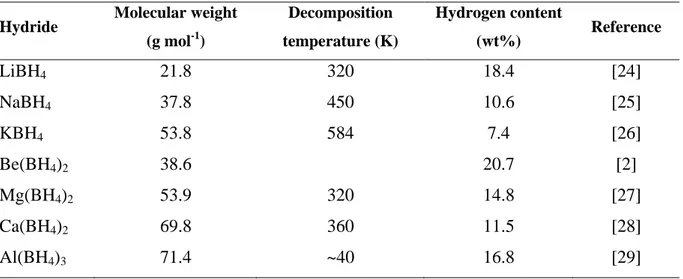
element from the first group or the second group of the periodic table and Me is usually either boron or aluminium [2]. The most well studied complex hybrid is LiBH4 which has proved to have hydrogen gravimetric density of 18 wt% [24]. Table 5 presents a comparative hydrogen gravity density of some well described complex hydrides.
As it is shown in Table [5], despite of their high hydrogen content, dehydrogenation (decomposition) of these complex hydrides is highly endothermic and demands a lot of energy. On the other hand those hydrides that adsorb and desorb hydrogen at ambient temperature and pressure mainly consist of transition metals and therefore the gravimetric hydrogen content is dramatically reduced (less than 3wt%). For instance, LaNi5H5 with a
volumetric density of 115 kg m-3 has a gravimetric hydrogen content of only 1.4 wt% [4]. To summarize hydrogen storage in hydrides, it must be emphasized that although metal hydrides and complex hydrides have the advantage of containing high hydrogen contents, the slow adsorption/desorption kinetics and heat release during their dehydrogenation process is a big obstacle in their usage as a commercial hydrogen storage medium. On the other hand those hydrides which possess a favourable adsorption/desorption kinetics have low gravimetric hydrogen contents.
38
Table 5 - Comparative hydrogen storage data of most common complex hydrides
Hydride Molecular weight (g mol-1) Decomposition temperature (K) Hydrogen content (wt%) Reference LiBH4 21.8 320 18.4 [24] NaBH4 37.8 450 10.6 [25] KBH4 53.8 584 7.4 [26] Be(BH4)2 38.6 20.7 [2] Mg(BH4)2 53.9 320 14.8 [27] Ca(BH4)2 69.8 360 11.5 [28] Al(BH4)3 71.4 ~40 16.8 [29]
1.5. Clathrate hydrates
Clathrate hydrates are inclusion structures made up of water and small (typically gas) molecules. Under appropriate thermodynamic conditions, i.e. high pressure & low temperature, water molecules form an enclosed hydrogen bonded structure (cages) around small captured molecules. Due to their potential in future energy storage, they have been subject of many researches, particularly over the last 20 years. This work, investigates clathrate hydrates as an alternative solution for hydrogen storage. Due to the focus of this work on clathrate hydrates as a storage media, a more detailed description of these compounds seems inevitable. For this reason, the first part of this work is dedicated to general properties of inclusion compounds and their different structure. In the second part a brief history of hydrogen storage in clathrate hydrates is reviewed.
1.5.1. Introduction
Natural gas hydrates are subset of a larger group of compounds known as clathrate or inclusion compounds. A clathrate is a compound in which a molecule of one substance (typically gas) is enclosed in a structure built from molecules of another substance [31]. Natural gas hydrates are composed of an aqueous solution and gas molecules in which gas molecules (guests) are trapped in water cavities (host). These cavities are formed as a result of hydrogen bonds between water molecules. Typical hydrate former constituents of natural gas are methane, ethane, propane, and carbon dioxide [30].
Although hydrates have been probably encountered by many chemists during history, it was Sir Humphrey Davy who first reported the formation of hydrate of chlorine in 19th century
![Table 1 - Comparison of heating values and CO 2 emission of common fuels and H 2 [1] Fuel Heating value (kJ/g) Chemical Formula kg[CO 2 ] / L](https://thumb-eu.123doks.com/thumbv2/123doknet/2719971.64409/22.892.102.791.552.896/table-comparison-heating-emission-common-heating-chemical-formula.webp)
![Figure 5 - Hydrogen bond in water molecule: a) between two molecules b) between four molecules [30]](https://thumb-eu.123doks.com/thumbv2/123doknet/2719971.64409/40.892.189.702.911.1099/figure-hydrogen-bond-water-molecule-molecules-b-molecules.webp)
![Figure 26 - A schematic T-P diagram of hydrate Formation - dissociation process in an isochoric reactor [30]](https://thumb-eu.123doks.com/thumbv2/123doknet/2719971.64409/78.892.244.655.425.821/figure-schematic-diagram-hydrate-formation-dissociation-process-isochoric.webp)