HAL Id: tel-02066158
https://pastel.archives-ouvertes.fr/tel-02066158
Submitted on 13 Mar 2019HAL is a multi-disciplinary open access archive for the deposit and dissemination of sci-entific research documents, whether they are pub-lished or not. The documents may come from teaching and research institutions in France or abroad, or from public or private research centers.
L’archive ouverte pluridisciplinaire HAL, est destinée au dépôt et à la diffusion de documents scientifiques de niveau recherche, publiés ou non, émanant des établissements d’enseignement et de recherche français ou étrangers, des laboratoires publics ou privés.
Modèle hybride pour simuler l’écoulement à travers un
birotor éolien caréné et sa validation expérimentale
Michal Lipian
To cite this version:
Michal Lipian. Modèle hybride pour simuler l’écoulement à travers un birotor éolien caréné et sa validation expérimentale. Génie des procédés. Ecole nationale supérieure d’arts et métiers - ENSAM; Institute of Turbomachinery, Lodz University of Technology, 2018. Français. �NNT : 2018ENAM0073�. �tel-02066158�
N°: 2009 ENAM XXXX
Arts et Métiers ParisTech - Campus de Paris DynFluid – Laboratoire de dynamique des fluides
2018-ENAM-0073
École doctorale n° 432 : Science des Métiers de l’ingénieur
présentée et soutenue publiquement par
Michal LIPIAN
17 Décembre 2018The hybrid simulation model for a twin-rotor diffuser-augmented
wind turbine and its experimental validation
Doctorat ParisTech
T H È S E
pour obtenir le grade de docteur délivré par
l’École Nationale Supérieure d'Arts et Métiers
Spécialité “ Génie énergétique ”
Directeur de thèse : Fawaz MASSOUH, Krzysztof JOZWIK (directeur cotutelle) Co-encadrement de la thèse : Ivan DOBREV, Maciej KARCZEWSKI (co-encadrant cotutelle)
T
H
È
S
E
JuryM. Michael TODOROV, Professeur, Technical University of Sofia Président
M. Piotr DOERFFER, Professeur, Polish Academy of Sciences Rapporteur
M. Frank RUCKERT, Professeur, Saarland University of Applied Sciences Rapporteur
M. Farid BAKIR, Professeur, Arts et Métiers ParisTech Examinateur
M. Krzysztof JOZWIK, Professeur, Lodz University of Technology Examinateur M. Fawaz MASSOUH, Professeur Emérite, Arts et Métiers ParisTech Examinateur
M. Ivan DOBREV, Docteur, Arts et Métiers ParisTech Invité
Rozpoczęty 12/10/2016, Paryż, Francja Wznowiony 26/08/2017, Łódź, Polska Zamknięty 07/08/2018, Łódź, Polska Poprawiony 18/09/2018, Burgas, Bułgaria Ukończony 18/10/2018, Łódź, Polska Oddany do druku 29/10/2018, Łódź, Polska
What’s past is prologue William Shakespeare, The Tempest, Act 2, Scene I
Ad astra Publius Vergilius Maro, Aeneid, book IX, line 641
Acknowledgments
The crafting process of what has become my PhD thesis wouldn’t be possible without people around me. To all those who helped me along the way I wish to forward my deepest thanks.
First and most of all I want to thank my parents and grandparents. I value the moral support You gave me during my long path of studies as the most precious assistance I got and could get from anybody. My very warm wishes go to my supervisors, prof. Krzysztof Jozwik and prof. Fawaz Massouh. Your doors were always opened for me and my ideas, no matter how backbreaking they would be. Your assistance and wisdom were soothing, Your help fighting the bureaucracy in Poland and in France – reassuring. Thank You for guiding me all the way to the end.
The work I have done would not be possible without the substantive support of my co-supervisors, Maciej Karczewski, PhD, and Ivan Dobrev, PhD. My especially warm sentiment goes to the latter, whom I consider a researcher au sens propre. Sir, I admire Your expertise and marvel Your workshop. It’s an honour to work with and learn from You.
To M. You came into my life when I didn’t expect, gave me what I didn’t seek and made me ask for more. You gave a new direction to my life and a new world to explore. Thank You for all Your help, interruptions, questions and answers. Thank You for making Your way through the walls around me. To M. Far or close, early in the morning or late in the evening - I can always count on Your assistance and council. Thank You for Your support of my actions and smart criticism when needed. Thank You for soothing conflicts and helping with burdens when they were pushing me down.
To my friends Filip and Philippe. Both of You are extraordinary characters of extraordinary intelligence. Thank You for Your straightforwardness and advice. A man is always in need of a good friend, and friends like You are a true blessing.
To all my friends and colleagues from the Institute of Turbomachinery. My special thanks go to Krzysiek, Piotr, Mateusz, Zbyszek and Grzesiek. Working with a self-proclaimed genius on a daily basis is a hard job. Thank You for bringing me back to Earth whenever my ego was surpassing my actions. To all those whom I met and worked with at Arts et Metiers ParisTech. I especially acknowledge the assistance of prof. Farid Bakir and prof. Patrick Kuszla. Your understanding and calmness always gave me hope for a positive end of my studies.
To the entire GUST team. We’ve been through ups and downs, as a team and as a group of individuals. Working with You for several years, watching You evolve and achieve targets impossible for others is the most precious gift that any tutor can get.
And finally – to every person reading this thesis. Whether it is need, order or pleasure that drives You, I hope You will share the joy that accompanied me during my work.
1
Table of contents
INTRODUCTION ... 6
BACKGROUND AND THE STATE OF THE ART ... 9
WIND ENERGY OVER THE CENTURIES ... 9
2.1.1. HISTORY ... 9
2.1.2. PRESENT STATE ... 13
2.1.3. FUTURE ... 15
SYSTEMATICS OF WIND TURBINES ... 16
DAWT AND ITS PERFORMANCE ... 19
TWIN-ROTOR WIND TURBINE SYSTEMS ... 21
THEORETICAL INTRODUCTION ... 25
FLOW ANALYSIS... 25
3.1.1. 1-D MOMENTUM THEORY ... 25
3.1.2. ROTATION EFFECTS ... 27
3.1.3. BLADE-ELEMENT THEORY (BET) ... 28
3.1.4. FLOW THROUGH DIFFUSER IN OPEN FLOW CONDITIONS ... 30
3.1.5. DIFFUSER-AUGMENTED WIND TURBINE (DAWT) ... 31
3.1.6. COUNTER-ROTATING OPEN ROTOR (CROR)... 33
SIMILARITY CRITERIA IN FLOW ANALYSIS ... 35
SOLVER DESCRIPTION, TURBULENCE MODELLING ... 37
EXPERIMENT ... 41
METHODOLOGY ... 41
WIND TURBINE TEST STANDS ... 42
EXPERIMENTAL CAMPAIGN COMPOSITION ... 44
OPEN ROTOR OPERATION ... 45
DIFFUSER-AUGMENTED WIND TURBINE (DAWT) OPERATION ... 47
COUNTER – ROTATING OPEN ROTOR (CROR) OPERATION ... 49
COUNTER – ROTATING SHROUDED ROTOR (CRSR) OPERATION ... 53
SUMMARY AND CONCLUSION ... 56
FULLY-RESOLVED ROTOR MODEL (FRM) ... 57
GENERAL INFORMATION ... 57 PREPROCESSING SCHEMES ... 58 5.2.1. STATIONARY DOMAIN ... 58 5.2.2. ROTATING DOMAIN ... 60 5.2.3. SIMULATION SETUP ... 61 MODEL EVALUATION ... 62 5.3.1. NUMERICAL VERIFICATION ... 62 5.3.2. EXPERIMENTAL VALIDATION ... 65
FRM - RESULTS AND DISCUSSION ... 67
5.4.1. FLOW VELOCITY THROUGH ROTOR ... 67
5.4.2. ANGLE OF ATTACK AND AERODYNAMIC FORCE COEFFICIENTS - SINGLE ROTOR ... 69
5.4.3. ANGLE OF ATTACK AND AERODYNAMIC FORCE COEFFICIENTS – TWIN ROTOR ... 72
5.4.4. TIP LOSS CORRECTION MODELLING - DAWT ... 73
2
THE HYBRID CFD-BET MODEL ... 77
GENERAL INFORMATION ... 77 AEROFOIL PROPERTIES ... 79 PREPROCESSING SCHEMES ... 83 6.3.1. SIMULATION DOMAIN ... 83 6.3.2. SIMULATION SETUP ... 84 MODEL EVALUATION ... 85 6.4.1. NUMERICAL VERIFICATION ... 85
6.4.2. EXPERIMENTAL VALIDATION, COMPARISON WITH FRM ... 87
DISCUSSION - CASE STUDY: CRSR WIND TURBINE ... 92
CRSR PERFORMANCE ASSESSMENT (ADM, EXPERIMENT) ... 92
TIME-AVERAGED FLOW FIELDS (ADM, FRM)... 94
INSTANTANEOUS FLOW FIELDS (URANS FRM) ... 96
SUMMARY AND CONCLUDING REMARKS ... 102
LITERATURE AND SOURCES ... 105
IMP TUL WIND TUNNEL ... 114
TEST STAND PREPARATION AND DIAGNOSTICS ... 121
A2.1 EQUIPMENT CALIBRATION, TEST STAND INFLUENCE ASSESSMENT ... 121
A2.2 FOURIER ANALYSIS OF THE OBTAINED SIGNALS ... 122
A2.3 HYSTERESIS ... 124
A2.4 VARIOUS TYPES OF BLADES ... 125
A2.5 UPWIND VS. DOWNWIND CONFIGURATION ... 127
A2.6 R1 VS R2 ROTOR ... 128
3
Funding
The research was carried with funding of the following projects:
Okanałowana turbina wiatrowa w układzie tandem dla polskiej mikroenergetyki (Diamentowy Grant DI2013 011843)
Small Wind Turbine Optimized for Wind Low Speed Conditions (Polish-Norwegian Research Programme 200957)
4
Symbols and notations
AoA Angle of attack (also α)
ADM Actuator Disk Model
ALM Actuator Line Model
BEM Blade-Element Momentum theory
BET Blade-Element Theory
SRWT Single-Rotor Wind Turbine
CROR Counter-Rotating Open Rotor
CRWT Counter-Rotating Wind Turbine
DAWT Diffuser-Augmented Wind Turbine
EU European Union
FDM Fused Deposition Modelling
FFT Fast Fourier Transform
FRM Fully-resolved Rotor Model
LES Large Eddy Simulation
PoR Plane of Rotation
RES Renewable Energy Sources
SWT Small Wind Turbine
TKE Turbulent Kinetic Energy (also k)
TSR Tip-Speed Ratio (also λ)
UDF User-Defined Function (ANSYS Fluent routine)
WT Wind Turbine
A m2 Area
B - Number of blades
Cd - Drag coefficient
Cl - Lift coefficient
Cp - Power coefficient (wind power extraction efficiency)
Ct - Thrust coefficient
D m Wind turbine diameter
Fd N Drag force Ft N Thrust force Ma - Mach number P W Power Q Nm Torque R m Rotor radius Re - Reynolds number RH % Relative humidity St - Strouhal number T K, oC Temperature
U m∙s-1 Streamwise velocity component
U∞ m∙s-1 Freestream wind velocity
V m∙s-1 Velocity
5
a - Axial induction factor
a’ - Tangential induction factor
c m Chord
cp - Pressure coefficient
d N∙m-1 Drag force per unit blade length
dt s Timestep
f Hz Frequency
k m2∙s-2 Turbulent Kinetic Energy (also TKE)
l N∙m-1 Lift force per unit blade length
m kg Mass
n - Wind turbine-to-diffuser exit area ratio, A/Ae
p Pa Pressure (notably static)
q Pa Dynamic pressure
r J∙kg-1∙K-1 Individual gas constant
t s Time
α deg Angle of attack (also AoA)
β deg Pitch angle
γ - Power coefficient based on the diffuser exit
ε - Air flow momentum loss factor
ζ deg Diffuser cone half-angle
η - Diffuser pressure recovery efficiency
λ - Tip-Speed Ratio (also TSR)
μ Pa∙s Dynamic viscosity
ν m2∙s Kinematic viscosity
ρ kg∙m-3 Density
ϕ deg Inflow angle
ω rad∙s-1 Rotational velocity
Subscripts: u upstream d downstream e (diffuser) exit n normal t tangential tot total w wake ∞ reference value
+ (immediately) upstream rotor - (immediately) downstream rotor Frames of reference:
(x,y,z) Coordinates in rectangular frame of reference X, Y, Z Directions (axes) of rectangular frame of reference (r,ϕ,z) Coordinates in cylindrical frame of reference
6
Introduction
According to the European Commission directive "20 20 by 2020" [1], the countries of European Union (EU) have to, by year 2020, limit the greenhouse gas emissions by 20%, increment energy efficiency by 20% comparing to 1990 levels, and increase energy production from Renewable Energy Sources (RES) to 20% of the energy mix Europe-wise (15% for Poland, 23% for France).
According to the former European Wind Energy Association (EWEA), in 2015 1266 MW in wind turbine (WT) power was installed in Poland. A number surpassed only by Germany, it accounted for 9.9% of all power installed in wind turbines in the EU in this period [2]. Thus, as of the end of 2017, wind turbines remain the most important converters of RES in the Polish market: 5858 MW, that is about 68% of all RES installed power [3]. The structure of the Polish wind market concentrates currently on the multi-megawatt machines condensed in wind farms. Unfortunately, the current legislation in force in Poland significantly curbs new investments of this type [4]. In the meantime Polish wind resources (see ex. [5]) seem to address the localized power harvesting, where each energy consumer may become a prosumer, addressing own electricity needs produced by Small Wind Turbines (SWTs). High efficiency is a key factor in such constructions, to economically justify their use.
In France, the nuclear energy has been a well-established leader of the market for several decades. In 2017 the nuclear power plants accounted for 71.6% of total annual electric energy production, followed by hydroelectric (10.1%) and natural gas (7.7%) power plants [6]. Installed power of wind turbines in France grew in 2017 by 15.3% but, alike in Poland, this was mainly concentrated in wind farms. Access to relatively cheap electrical energy from nuclear power plants, along with shortage of precise wind resource data at low heights make small wind turbines hardly rentable in the continental France [7]. This situation changes, however, if Overseas France is taken into account, where SWTs may answer the needs of isolated locations. Efficient and reliable operation is a key factor in this case. SWTs usually operate at low wind speeds and adverse range of Reynolds number values. This significantly limits the possibility of aerodynamic blade optimisation and promotes research towards more sophisticated solutions. The promising ideas include Diffuser-Augmented Wind Turbine (DAWT), previously studied at the Institute of Turbomachinery, Lodz University of Technology (IMP TUL), and Counter-Rotating Rotors (CRR). The diffuser promotes an increase in the wind mass flow rate through the rotor, which translates into higher wind turbine power and energy outcome. This solution also has an advantage of protecting against blade breakage and potential to damp the wind turbine noise. The CRR explores possibility of extracting the kinetic energy of wind in the wake. This concerns most of all the axial component of wind speed, but may also apply to the tangential component, which is normally lost in the form of a rotating wake.
To answer the above challenges the project Twin-rotor Diffuser-Augmented Wind Turbine for Polish
wind speed conditions was proposed. It combines the concepts of DAWT and twin-rotor. The DAWT is
already commercialized i.a. in Japan and United States, which proves its purposefulness. At the same time it is tempting (and not yet exploited) to profit further on from the wind velocity increase due to diffuser, by placing the second rotor in the augmented velocity region(s). This novel idea is hoped to rise the overall efficiency of the system, thus decreasing the effective price of electrical energy per kWh and further on – making the investment in RES economically reasoned.
The main objective of the thesis The hybrid simulation model for a twin-rotor diffuser-augmented wind
7
turbine and to analyse the flow through this kind of a device. This task requires advanced tools of flow analysis, both numerical and experimental. However, due to the complex nature of the flow, experimental methods have only limited applicability. For example, PIV measurements techniques would be very hard to apply due to technical reasons. Experimental tests are also limited by the scale effects, which would occur for testing relatively small models, and who is not present a priori in the case of simulations. Hence, and owing to a multitude of functional parameters of the concerned system, the main focus of the thesis will be put on the simulation tools. This is due to the fact that they enable a relatively facile modification of parameters such as the geometry of rotors and/or their relative position. The complicated character of the problem, however, makes complete modelling of the rotors (FRM, Fully-resolved Rotor Model) prohibitively resource-consuming (due to mesh size, time of calculations, etc.). Thus the idea to employ a simplified, hybrid model seems to be reasonable. Such approach represents the wind rotor by source terms in Navier-Stokes equations. These source terms can be applied within a thin disk which represents the entire rotor (ADM, Actuator Disk Model), or around lines representing the blades separately (Actuator Line Model - ALM).
An important added value will be due to the dedicated experimental campaign, performed at the IMP TUL wind tunnel. The results will be used for model validation and further flow analysis.
The following hypothesis has been forwarded:
Creation of a hybrid simulation model of a twin-rotor diffuser-augmented wind turbine will enable a sterling analysis of this system’s functioning.
The following scientific objectives were assumed:
creation of a hybrid simulation model for two counter-rotating shrouded wind turbine rotors,
creation of experimental apparatus of the above mentioned system in the wind tunnel for functional analysis of the system and validation of the hybrid simulation model basing on the experiment-simulation integration approach.
The thesis is composed of 8 chapters and 3 appendices.
Chapter 1 presents the motivation for the proposed work and discusses the content of the thesis. presents the scientific formulation of the problem, defines the thesis’ argument and scientific goals. Chapter 2 gives an introduction into the subject of wind energy. Wind usage history and practical aspects are discussed, followed by the State of the Art analysis in the subject of both ducted- and twin-rotor wind turbine systems.
Chapter 3 provides the essential physical concepts and mathematical formulations used in the current thesis. This includes the main principles of a flow through wind turbines of various construction, the dimensionless analysis principles, governing equations.
Chapter 4 presents the experimental study performed in frames of the thesis. Measurement methodology is presented and evaluated. The results obtained for 4 cases: bare- are shrouded wind turbines in both single- and twin-rotor configurations are presented.
Chapter 5 evaluates the first of the proposed numerical models, that is Fully-resolved Rotor Model. Model validation and verification are performed, followed by the presentation and discussion of
8
results for selected wind turbine configurations. An evaluation of results is performed towards their further use in a hybrid model validation process.
Chapter 6 presents the developed hybrid model. General information concerning the aerofoil data and in-house-developed code are given, so as to explain its principles. Model description is then presented, followed by its verification and validation.
Chapter 7 compares the outcomes of 3 different employed research paths. Results for a Counter-Rotating Shrouded Rotor (CRSR) are compared, where applicable. A discussion then follows concerning the examined structure, in which the complementing results are used to evaluate the system’s performance and eventual further development paths.
Chapter 8 is a summary of the performed works, conclusions and recommendations for future works. Appendix 1 shows the research pertaining to flow evaluation in subsonic wind tunnel of the Institute of Turbomachinery, Lodz University of Technology, in which experimental study for the thesis was performed.
Appendix 2 evaluates on the practical aspects of the measurement campaign, such as preparation and diagnostics of the test stand and model.
Appendix 3 presents the information concerning the wind nature and assessment, basing on a dedicated experimental campaign.
9
Background and the State of the Art
This chapter starts with overview of wind energy aspects from the historic and statistic points of view. It then proceeds to technical aspects pertaining to wind energy exploitation, from wind resource assessment, through different types of wind turbines, to finish with the State of the Art analysis.
Wind energy over the centuries
Wind is among the earliest energy sources discovered and adopted by human beings. This Section presents the evolution of wind harvesting, its present state and future perspectives.
2.1.1. History
There is no general consensus over the time and place where the mankind began harvesting the wind energy. Ancient China and Egypt are usually named as the pioneering civilisations to use a sail for riverine and deep-water vessels as early as 4000 BC – 3400 BC [8]. Wind-propelled ships were to dominate the rivers for the next millennia, until the successful application of a steam engine at the turn of 18th and 19th century [9]. Even then the sails were often maintained as an auxiliary source of
propulsion.
Where and when the first windmill was installed is a question open to interpretation. Babylonian ruler Hammurabi is said to have wanted to employ windmills for irrigation purposes in Mesopotamia as early as 1700 BC, although no accounts exist of actual operating installations [10]. Some interpretations of the ancient Hindu texts suggest that windmills were commonplace in India for similar usage around 400 BC [11]. Both Heron of Alexandria and Vitruvius mention the use of “wind-vanes” in the 1st and 2nd
century Europe, although these were proved to be musical organs, rather than windmills. In China, windmills might have existed during the Eastern Han Dynasty (25-220), as proved by the paintings in tombs unearthed near Liaoyang City near the Yellow Sea [8].
The first fully confirmed use of vertical-axis windmills (panemones) was at the Persian-Afghan borders circa 200 BC. The rotors were shrouded, with slotted circular walls enabling the wind passage through rotor. These primitive windmills were used to pump water and grind grain [12]. Gradual expansion of these constructions towards India, China and Arab countries followed, most probably thanks to merchants and sailors. In England, the horizontal-axis windmills emerged, when in 1137 William of Almoner constructed such a “post-mill” in Leicester. The devices were placed on a vertical post (hence the name), and manually-positioned towards wind. Primitive as they were, these machines were lift-operated, and thus significantly more efficient than the Persian drag-operated vertical-axis constructions. This and substantial technical differences suggest that there was little, if any, connection between the two concepts [13]. As the windmill was popularised in continental Europe, the pole was replaced with a more elaborate construction of stone or brick, thus creating a (typically 4-bladed) tower mill. This construction has become a common landmark in Western Europe, notably the Netherlands. The Dutch extended the traditional use of windmills to propulsion of sawmills, paper factories, grinding machines. They are also credited for transporting the technology to the New World, around 1750. By that time in Europe there were an estimated number of 10 000 wind-powered devices in UK and German States, 8 000 in The Netherlands, 5 000 in Denmark [12]. However, a quick decline in these numbers in Europe was at the doorstep, with arrival of more reliable and mobile steam engine. Still, an estimated number of 6 million “American farm windmills” operated between 1850 and 1900 in the American Great Plains, becoming eventually an USA interior icon. These machines were
10
characterised by relatively large number of blades, compact construction, easy maintenance, self-regulation and low price [13]. Examples of the discussed constructions one can find in Fig. 1.
Fig. 1 Evolution of windmills: a) panemone (modern) [14], b) post mill [15], c) tower mill [16], d) American windmill [17]
The great comeback of windmills arrived once they were married with the new technical innovation - electricity. Thus was created a wind turbine (Fig. 2), enabling to separate the energy production and consumption places. Claimed to be the first practical construction of this type, a 12 kW, 144-bladed HAWT (Horizontal-Axis Wind Turbine) of rotor diameter 17.1 m (56 feet) was installed in 1888 in Cleveland, Ohio, by Charles Brush [13]. This model was never duplicated or commercialised, contrarily to works of Poul la Cour in Denmark. He developed a wind turbine experimental station at Askov, about 30 km from the North Sea coast. Rotors of diameter up to 23 m were usually connected with DC dynamos and had electric output in the range of 5 and 25 kW.
a
b
c
11
Fig. 2 Wind turbine history in images [18], [19], [20], [21], [22], [23], [24], [25], [26]12
By 1920 several hundreds of HAWTs were operating in Denmark nationwide, generating a total power of as much as 120 – 150 MW. They were a significant relief to the population struck by fossil-fuels shortage during WWI and later WWII. This observation was not left unnoticed abroad and the interwar period saw a worldwide development of modern wind turbines. USA (Jacobs, Putman), USSR (Kranovsky), France (Darrieus), Germany (Kumme) may be given as examples of both domestic and bigger-scale wind turbine projects [12]. The American Smith-Putnam project was possibly the most significant of the above mentioned. Palmer Cosslett Putnam erected a two-bladed wind turbine of 53 m diameter on Grandpa's Knob in Castleton, VT, USA. The rotor, rated 1 - 1.25 MW (at wind velocity of 13.2 m/s), operated from 1941 to 1945, when one of the blades separated from the hub and crashed. Apart from the project being recognized as the first megawatt-size wind turbine, it is also acclaimed for the way it was conducted. It was financed by the private industry (S. Morgan Smith Company) and included a set of prominent scientists and energy companies of the time. As stated by Pasqualetti [13] “What is most remarkable about the Smith-Putnam project is not its successful operation but rather the fact that it happened at all”.
The arrival of a modern wind turbine is usually associated with the Gedser model constructed by Johannes Juul for electricity company SEAS (Sydsjællands Elektricitets Aktieselskab) in 1957. The 3-bladed, stall-regulated upwind rotor of 24 m diameter was connected to asynchronous generator. Rated power was equal to 200 kW at wind velocity of 15 m/s. After the 1973 oil crisis numerous government-funded programs for development of wind turbines were launched, resulting in a significant increase in nominal power of wind turbines. Notable examples include American Mod-5B (97.5 m rotor diameter, 2.5 MW, 2 blades, HAWT) and Canadian Éole (110 m-high height, 4 MW, Darrieus rotor). The Gedser wind turbine architecture, dubbed the “Danish concept” was successfully used for wind turbines as big as 60 m diameter and nominal power of 1.5 MW. This was finally the concept that dominated the way we think about wind turbines today [13], [27].
The second oil crisis in 1979 led the governments (e.g. Denmark, USA) to reconsider their energy policies. At that time the state of California decided to subsidise the conversion of renewable energy sources. What’s more, the state started measuring wind resources and sharing the information publicly. This came along with the opening of the state utilities and energy market. All these pieces formed a massive development of wind turbine installations and wind farms all over the state. They totalled to an estimated number on 11 000 units (mainly of order 50 – 200 kW per machine) by the end of 1980s, when the rush began to fade away due to citizens’ complaints, subsidies’ ceasing and increasing regulation. The California example provided experience and warnings necessary when considering future wind project policies [13], [25].
Back in 1984 Musgrove [28], [12] predicted, basing on the then-actual research, that medium-sized (15 m – 20 m diameter) wind turbines could harness, during the same period, the same amount of wind energy less expensively than large, multi-megawatt-scale rotors. The development of new materials and technologies had proven this theory to be wrong, as scaling-up the rotor enabled to increase the wind turbine capacity factors. From 1983 to 2016 the average global wind turbine diameter rose from 17 m to 101 m, and the capacity factor from 20% to 28% [29].
The scale-factor was to be crucial especially for the emerging offshore wind farms. In 1991 the first structure of this type was installed in Vindeby, 3 km offshore the coast of Denmark. Wind turbines of total power of 11 450 kW, adapted for offshore wind conditions, were operating until final
13
decommissioning in 2017, after having produced a total energy of 243 GWh in their lifetime. The technology has advanced significantly since that pioneering undertaking. London Array, the biggest offshore wind farm in the world (by capacity: 630 MW, as of July 2018), comprises of 175 3.6 MW SWT-3.6-120 HAWTs produced by Siemens Wind Power. Placed 20 km offshore United Kingdom, it has annual energy output of 2500 GWh (2015).
Over the centuries wind turbines have grown in size, their technology has matured, their applications have diversified. The nature of the wind remains unpredictable, but the humankind has developed tools to extract its energy in an easier and more practical way than ever before.
2.1.2. Present state
According to Burton [27], the interest in development of wind turbines back in 1970s was the oil crisis. In 1990s this shifted towards increasing concerns about greenhouse emissions. Currently, wind energy is also seen as a means for diversification of energy sources, thus securing the energy market.
The above consideration is a very important aspect for example in EU, struggling lately to decrease energy market dependence on foreign sources. WindEurope (former EWEA, European Wind Energy Agency) states in its Wind in power 2017 report [30] that 15.6 GW in wind power (55% of all new power) was installed in EU in 2017. 20% accounted for offshore installations. As of 2017, wind turbines are the second-largest installed capacity in EU (18.0%, after gas – 20.1%), covering 11.6% of EU annual electricity demand (see Fig. 3).
Fig. 3 2005-2017 evolution of installed power generation capacity in the EU [30]
In Poland, as of the end of 2017, power of 5858 MW installed in wind turbines accounted for 13.5% of the entire national energy mix [3]. The wind turbines in Poland are mainly grouped in wind farms, although the current legislation concerning RES ([4] and amendments) is heavily against this kind of installations. Thus construction of the new (and replacement of the old) megawatt-range wind turbines has virtually stopped since 2016, when new laws were introduced. This, however, has given field to alternative approach to RES, with increasing role of prosumers. According to the statistics presented
14
in Fig. 4 for year 2017, about 56% of new RES power capacity was installed in sources of power lower than 50 kW. Average power size of these installations was about 6.5 kW, while for the bigger systems it was about 880 kW. To put this statistics into perspective, power of 225 kW in 35 new small RESes was installed each day in Poland in 2017. Even though an important part of these systems was in solar power, this statistic is an important indicator of increasingly positive sentiment towards prosumer, small-size RES, and hence the need for development of this kind of installations.
As for France, the metropolitan electrical energy market has been dominated by two sectors: nuclear power (72% market share, 398.4 TWh generated in 2017) and hydraulic power (9%, 49.2 TWh). At 24 TWh produced in 2017, wind turbines account for approximately 5% of the total energy market and 1.8 GW of new power was installed in wind turbines in 2018 (Fig. 5) [31], [32]. These are mainly big-scale wind turbines, both onshore and offshore. According to the analyses by ADEME (l'Agence de l'Environnement et de la Maîtrise de l'Energie) there is little interest in implementing SWTs in the French metropolitan electric grid to balance the national energy demand-supply, due to scale effect. It is the difficult since no reliable wind assessment data is available for SWT height range. However, the same report underlines the potential of SWTs in two contexts: prosumer approach (noting the importance of feed-in tariffs) and isolated sites [7]. The latter may be especially interesting, having in mind the French overseas territories.
Fig. 4 RES power installed in Poland in 2017 in small (<50 kW, left) and big (>50 kW, right) scale systems: data from 5 biggest Poland’s electricity providers (99% of market share by power), data source: [3], [33]
4162 4098 2245 1808 370 25.9 MW 24.6 MW 16.8 MW 12.9 MW 1.9 MW
PGE Dystrybucja Tauron Dystrybucja Energa Operator Enea Operator innogy Stoen 37 10 18 7 1 29.2 MW 1.9 MW 16. MW 16.2 MW .7 MW
PGE Dystrybucja Tauron Dystrybucja Energa Operator Enea Operator innogy Stoen Total: 82.1 MW 12683 installations Total: 64.0 MW 73 installations
<50 kW
>50 kW
15
Fig. 5 2017 wind energy statistics per regions of metropolitan France: installed power (left) and annual electric energy demand covered (right) [32]
2.1.3. Future
From the engineering point of view, development of wind turbines towards larger rated powers and rotor diameters is the general tendency. Especially the offshore applications call for ever bigger and more powerful wind turbines. The leading model up to date (July 2018) is Vestas V164 platform, with 9.5 MW (rated wind speed of 13 m/s) model being the most powerful serially produced wind turbine. Each of three blades of the 164 m diameter rotor is of the mass 33 000 – 35 000 kg [34]. GE Haliade-X 12 MW wind turbine (rated wind speed not yet specified) is currently under development. With 107 m long blades the total height of the wind turbine will be 260 m [35]. These wind turbines are mainly targeted towards offshore wind energy, expected to grow rapidly in the upcoming years.
A completely different direction of wind turbine design lies at the basis of development and application of Small Wind Turbines (SWTs). In this approach the wind turbine user is usually a so-called prosumer (person/institution being at the same time both producer and consumer of energy). The prosumer energy generation permits to produce electric energy directly in the place of its consumption (distributed energy generation) and sell the possible surplus. The concept has been evolving in the EU to become a part of its official energy policy. According to the Polish law the small RES (also known as RES microscale installation) has a power no higher than 50 kW, while for example in USA this limit is equal to 100 kW. Taking this country as an example, 1.6 MW (3200 units) of SWTs was installed in 2017 at a cost of about 10 M USD. This is a decline compared with 2016. However, the SWT market is expected to rise significantly in years to come, due to increasing standardisation and certification, and a bipartisan agreement for financial aids for this type of installations [36]. This thesis will concentrate on a concept of a small wind turbine of a twin-rotor, shrouded construction.
A so-called “third way” has emerged lately, that is “community wind”, seen especially often in Denmark and Germany. In this approach a community or group of citizens would install collectively a small wind turbine cluster or a single megawatt-range wind turbine to produce electrical energy for common needs. The modular nature of wind energy makes it possible to scale the wind energy source for the needs of decentralized consumer network. According to Gipe [25] “[Wind turbines] may be owned
16
individually, cooperatively or mutually through numerous mechanisms. The key is for the community to identify the turbines as its own”. It might be said that the community wind promotes wind energy by bringing it directly to them, as a common good. Samsø island in Denmark is a good example of this approach. A community of about 3700 people is energetically fully self-sufficient thanks to wind turbines and biomass combustion [25]. In USA in 2017 the community wind approach constitutes 2.5% of installed wind power, with 15 new installations (48.5 MW in total) installed that year, ranging from 750 kW to 1.5 MW. This suggests an increasing interest in this form of operation in the near future [36].
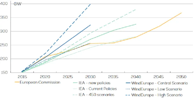
The future of wind energy in EU is generally given in a favourable manner. Regardless of source, the steady development is envisaged in the years to come, with development of all the aforementioned branches of wind energy generation (Fig. 6). The main questions for the future include the Europe-wise strategies introduced by EU, rate of wind energy market development in the Western Europe and local policies introduced in Eastern Europe. Nevertheless, wind energy is expected to cover as much as 20 – 30% of EU’s energy demand in 2030 [37].
Fig. 6 Scenarios for cumulative wind power capacity development in the EU 2016 – 2050; IEA 450 scenarios – International Energy Agency plan to curb the global temperature increase in 2100 to 2°C
above preindustrial levels [37]
Systematics of wind turbines
Although technically the concepts described in this and further sections stand correct for all types of windmills, from now the text will refer to wind turbines, being a connection of a windmill and generator, and thus producing electricity. Although technically fitting this definition, emerging technologies such as kite wind turbines are not included in this study.
The orientation of wind turbine axis of rotation is possibly the most apparent means to categorise these machines. Thus the HAWTs and Vertical-Axis Wind Turbines (VAWTs) may be distinguished [25]. This distinction is, however, not as precise as it may seem - a VAWT may also operate efficiently if placed horizontally [38]. Thus it might be more proper to divide the wind turbines by the direction of their axis with respect to that of wind. By this definition the parallel direction would refer to the
17
HAWTs, while transverse – to all types of VAWTs, regardless of whether the axis is placed horizontally or vertically. Although this definition was used for example in the original US patent by Darrieus [26], it has not caught on.
A majority of the traditional VAWTs falls into one of two categories: Darrieus- and Savonius-type (Fig. 7). The Darrieus rotor consists of slender blades fixed to a rotating shaft. In the most common design the blades of a constant cross-section are curved and fixed to the mast in two places, at its top and bottom, similar to a Greek letter phi (Φ). The aforementioned Éole wind turbine is a two-bladed wind turbine of this configuration. It was only used very briefly, due to significant vibrations. Today the parked rotor serves mostly as a tourist attraction [39]. Variants of Darrieus wind turbines exist, of which H-rotor (giromill) is the most notable. In this design the blades are supported to the shaft via additional beams. In its simplest design the straight, constant-section blades are placed parallel to the axis of rotation. Despite its simplicity, the Darrieus rotor has gained a limited practical use, mainly due to its inability to self-start. This disadvantage may, however, be overcome, for example by special pitch-control systems or an additional start-up device, like Savonius VAWT [25]. The Savonius rotors consist usually of two opposed, hollow semi-cylindrical blades, giving an S-shaped cross-section if seen from above. Due to its curvature, the blade experiences less drag when moving against the wind than when moving with the wind, causing the Savonius to spin. Their ancestors may be assumed to be the above mentioned historic Persian rotors.
Fig. 7 Examples of typical domestic-size VAWTs [40], [41], [42], [43], [44], [45]
From the aerodynamic point of view, the Darrieus rotor is a lift-driven, while the Savonius is a drag-driven device. This makes the Savonius rotor less efficient, but also more appropriate for placement at low heights. Despite their obvious advantage of omnidirectionality without yawing and ability to operate at lower wind speeds/rotational velocities, field tests prove VAWTs to be generally less cost-efficient than HAWTs. This may, however, change in future, as features such as twisted blades become more common in VAWT design [25].
In case of HAWTs, the most common approach is to divide them by the number of blades (Fig. 8). Wind turbine needs only one blade to harvest the wind energy. The single-bladed rotor operates at relatively high rotational velocities. Thus it normally does not require a gearbox to assure high rotational velocity for the generator to work efficiently. This, along with the lower number of blades, results in a reduced price. However, a single-sided loading introduces significant cyclic loads in the shaft and bearings, thus
18
a counter-weight is necessary. The blade must also be stronger than in multiple-blade designs to sustain aerodynamic and mechanic loads. Higher rotational velocity also means a higher level of noise emission. In all, no single-blades HAWT has withstood the test of time, despite notable examples coming from Germany (MBB, up to 640 kW) and Italy (Riva Calzoni, up to 300 kW) [25].
The two-bladed HAWT design was particularly popular in the 1970s and 1980s. The design offers much better dynamic behaviour compared to a single-bladed rotor, facilitating the rotor balancing. However, the aerodynamic efforts on the blades still require a relief system, practically realised by means of teetering (movement of the rotor back and forth with respect to principal plane of rotation). Gipe [25] estimates that, as of 2016, at most 250 twin-bladed HAWTs operated worldwide, accounting for no more than 0.1% of wind turbines globally.
As it follows from the classic 1D flow theory (see Subsection 3.1.1) an ideal HAWT rotor should have an infinite number of (infinitely thin) blades. The increase of number of blades is, however, practically limited. This comes from factors such as elevated price of rotor (due to high number of blades), blades material (providing enough stiffness at low cross-section), difficulty in gearbox/generator design (generators generally need to be provided with a sufficiently high rotational speed shaft), complex design of rotor hub. Thus the multi-blade HAWT rotors, although historically significant, are encountered today almost exclusively in special applications, such as micro-wind turbines installed on yachts (e.g. Rutland Windcharger [46]).
Having the above in mind it becomes clearer why a majority of today’s HAWTs possesses a three-bladed rotor. It offers the best compromise between efficiency, mechanical properties (blade loading) and environmental impact (noise, visual aspects). Hence the three-bladed design is found in both most powerful large wind turbines in the world, and most popular small ones (e.g. Bergey WindPower [47]).
Fig. 8 Examples of domestic-size HAWTs, divided by number of blades (left) or rotor-nacelle relative position [48], [49], [50], [51], [52], [53]
HAWTs may also be classified basing on the relative position of the rotor with respect to the nacelle, that is upwind (the most common design) or downwind type. The latter design has an important advantage of self-orientation towards wind (passive yaw). To increase this effect the blades may be coned, by about 1° - 10°, depending on the blades size. However, as proven by the experiments (Section A2.5 in Appendix 2), the tower’s aerodynamic shadow decreases the obtained power. It may also increase the level of noise emission. The downwind HAWTs also tend to operate less steadily than
19
upwind rotors, notably in high wind conditions. Consequently, the upwind HAWTs (equipped with tail vanes or active yaw control systems) remain the most common designs [25].
To sum up, wind turbines may be classified as of either VAWT or HAWT type. The latter type, in three-bladed upwind rotor configuration, is the most basic design of a contemporary wind turbine. This thesis will concentrate on a three-bladed HAWT exclusively.
DAWT and its performance
Although the concept of a stator-equipped wind turbine was studied back at the beginning of the 20th
century, the first practically realisable solutions were presented around the 1980s. Igra [54] was studying diffusers of a long form, inspired by the turbomachines. Gilbert and Foreman [55] proposed a construction based on an aerodynamic profile (Fig. 9). The drawback of these early solutions was their big size and mass - thus also the cost. There was little practical interest in the solution, due to its financial inefficiency. The concept remained unexplored until the addition of a flange (or a brim) at the diffuser exit (Fig. 10), as proposed by Abe and Ohya [56].
Fig. 9 Artist’s impression of an early, 60 m-diameter DAWT [57]
Fig. 10 Streamwise sectional view of a modern DAWT [56]
The research pertaining to DAWTs is currently most advanced in Japan, where DAWTs, born by the name “Wind Lens”, are already commercially available. The Wind Lens Turbine WL5000 collects up to 5 kW of power from a wind in wind speed range 12-17 m/s. Its three-bladed rotor has a diameter of 2.5 m, the outer flange diameter is 3.4 m. The structure is 4.24 m high of the mass of 650 kg and may be installed either on a pole or a rooftop [58]. In parallel, the researchers investigate the possibility of larger DAWTs (100 kW, 12.8 m - diameter test turbines operate at Ito campus of Kyushu University, [59]), and use of this technology in offshore applications (on floating hexagonal platforms collecting also solar and tidal energy).
As stated by Igra [54], in the case of an open rotor the entire flow field is typified by atmospheric pressure. The shroud, in the other hand, may support sub-atmospheric pressures in the vicinity of the turbine, thus increasing the role of dynamic pressure in that region. As stated by the mass continuity, the increase in cross sectional area of the diffuser decreases the axial velocity, producing a corresponding increase in pressure. Hence, the diffuser inlet is at a significantly lower pressure than its exit. When a wind turbine is placed at the diffuser inlet, the shroud increases significantly the mass flow and total pressure drop across the turbine. The power available to the turbine is proportional to this product [60].
20
In a profound analytical study, Lilley and Rainbird [61] compared the performance of an open-rotor and a ducted wind turbine. The authors performed calculations employing the 1D flow theory, as well as the vortex theory. They were able to estimate that the shrouding may result in an increase in a power outcome of an ideal wind turbine by 65%, but pointed out that the calculations would have to be benchmarked with experimental study.
Foreman et al. [62], after a study performed for Grumman Aerospace Corporation, identified the static pressure decrease at the diffuser exit (well below atmospheric pressure) as the factor responsible for flow velocity augmentation in DAWT. The authors stated that an efficient way to increase the performance would be to increase the outlet-to-inlet area ratio. This can be achieved by elongating the diffuser (which is economically inefficient) or increasing the cone angle. The latter solution provokes, however, occurrence of boundary layer separation inside the diffuser – the main reason of efficiency drop. To address this issue, the authors proposed two solutions: slots, that would permit boundary layer mixing and regeneration inside the diffuser, thus reenergizing it and preventing separations, and construction of the diffuser from short aerofoil sections of optimal pressure distribution. The authors claimed that by employing both solutions they were able to double the WT (wind turbine) efficiency. They concluded that the DAWT solution may be a competitive way of increasing the WT power outcome with respect to elongating the blades for small (diameter D < 20 m) and large (D < 50 m) turbines.
A different approach is proposed by Abe and Ohya [56], where the diffuser is brimmed. The authors proposed a 2D actuator model of a flow through DAWT, in which the presence of a wind turbine is modelled by inserting additional source terms to the Navier-Stokes equations in the axial (streamwise) direction. The thrust force was computed using dynamic pressure at the diffuser inlet (with no precision whether it is an averaged or local value), and a constant load coefficient. The force thus determined was applied in a rectangular zone at the diffuser inlet. Reynolds number computed basing on the rotor diameter is equal to Re = 20 000. The study shows that, for increased performance of WT, its loading coefficient should be lower than that for an open rotor (due to higher flow velocity at which ducted WT operates). It is once again underlined that the performance of a DAWT depends on the occurrence of separation inside diffuser. The increased loading may provoke the occurrence of separations, which in turn would decrease the performance.
In a more advanced study by the same team (Abe et al., [63]) the WT load was estimated using the Blade Element-Momentum theory (BEM), thus accounting for the actual profile characteristics and blade geometry. The study compared bare and ducted three-blade wind turbines, by means of 2D simulation (Re = 20 000) and experiment (Reducted ≈ 200 000, Rebare ≈ 300 000). The experimental
investigation included hot wire anemometry and power determination (by measuring the torque Q and rotational velocity ω). Despite the coarseness of the applied numerical model, a satisfying agreement with experiment was observed for turbine operation conditions that do not provoke flow separation at the blade surface. However, for low and very high rotational velocities (i.e. outside the usual operating range) the model lacked proper prediction of the flow character and predicts incorrect results. Hot wire measurements permitted also to reconstruct the velocity field around bare and shrouded WT. Flow immediately downstream blades was similar in both cases, with only minor differences in the tip region. In return, strong dissimilarities were observed further on, with a rapid destruction of vortex wake in case of DAWT, credited to the damping effect of diffuser.
21
Finally, in [64] and [65], the same research team proposed a yet more refined numerical 3D models. By applying respectively Actuator Disk (ADM) and Fully-resolved Rotor (FRM) approach they tried to capture the 3D phenomena downstream three-blade rotor. The ADM was firstly examined with no actuator force applied (empty diffuser), then with source terms calculated by the BEM code. In both cases the model was capable of catching properly the time-averaged flow structure inside diffuser, namely the flow velocity and static pressure. The authors proposed an in-house, empirical tip loss correction that assumes linear decrease of actuator force near the blade tip for shrouding of compact form (where diffuser damping effect is less evident). Meanwhile, the FRM approach employed a non-stationary, 3D moving boundary Large-Eddy Simulation (LES). The authors were able to identify what they claim to be an “induced blade tip vortex”: a twin structure appearing between the blade tip and duct’s inner surface, rotating in the opposite direction to the “normal” blade tip vortex. Its generation is explained by the interaction of blade tip and diffuser inner surface boundary layer. The role of induced blade tip vortex is to thin the boundary layer of diffuser inner surface, and decrease the possibility of flow separation downstream the rotor. As a result, pressure recovery from the diffuser entrance to the exit improves, owing to increased performance. The interaction and mutual weakening between induced and “normal” blade tip vortex is also credited for damping effect of the diffuser. IMP PL also performed own experimental research in the low wind speed wind tunnel of the institute [66]. The experiment involved PIV flow imaging of an empty diffuser, pneumatic measurements and wind turbine model power determination.
Twin-rotor wind turbine systems
Following the classical 1D momentum theory by Betz (see ex. [67]) the wind turbine power coefficient (ratio of WT shaft power and wind power) Cp is limited by a value of Cpmax = 16/27 ≈ 59% (a so-called
Betz limit). Achieving this value would require drop of the axial velocity across the rotor by 2/3. The
limit is altered further on when the rotational phenomena are taken into account (see Subsection 3.1.1).
In the case of “classic” turbines (ex. vapour turbines) Charles Gordon Curtis addressed this issue by patenting [68] an impulse turbine composed of a series of stages. This design takes advantage of the so-called velocity compounding, which enables one to decompose the energy extraction process into several nozzle-rotor series. The rotor blades would be installed on a common rotating shaft. This construction’s smaller size, as compared to the contemporary solutions, was its main advantage. Due to a lack of nozzle blades, in the case of wind turbine the two rotors are usually counter-rotating. Appa [69] proposed a twin-rotor counter-rotating wind turbine composed of two rotors of the same geometry (diameter D = 4 m and tip-speed ratio λ = 6). The rotor separation distance was not explicitly given by the authors, but may be estimated at D/4. Authors estimated by calculations that the theoretical overall Cp of the system could attain values even up to 85%. The study also incorporated the prototype fabrication and tests. Each one of two-blade rotors was mounted directly on a permanent magnet drum, turning around a stationary armature and thus forming an alternator. The prototype was tested in atmospheric conditions for 5 days a month, over 5 consecutive months. Mechanical power and wind speed measurements permit to estimate the turbine efficiency, as seen in Fig. 11. The researchers managed to increase the system Cp by 25 - 40%, as compared with single-rotor, and this gain was most visible for low rotation velocities. The authors also claimed that the buffeting phenomenon (high-frequency instability, caused by airflow separation phenomenon) was
22
not observed. They concluded that the solution might be suitable for retrofitting of existing wind turbine units, with estimated cost return time of approximately 3 to 5 years.
Fig. 11 Experimental power coefficient Cp for each rotor and overall system [69]
Shen et al. proposed [70] a 3D unsteady simulation employing Actuator Line Model (ALM). Two three-blade Nordtank 500 kW wind turbines (D = 41 m, rated λ = 5.81 at U∞ = 10 m/s) were considered under
pure counter-rotation (i.e. rotational velocity of each rotor has the same magnitude and opposite sign). Firstly the separation distance was varied from 0.05D to 0.4D at rated operational conditions. The authors observed that a decreased separation distance had a significant influence on the stability of the system (high fluctuations of torque and thrust force were observed for low separation distance). Next, the influence of changing TSR was examined (Fig. 12a, λ = 1 to 5.81). Increasing the rotational velocity at constant U∞ = 10 m/s and separation 0.25D leads to increase in Cp. Finally, the influence of
U∞ is examined (Fig. 12b), with conclusion that there is a significant superiority of twin rotor
Counter-Rotating WT (CRWT) over a Single-Rotor WT (SRWT) visible for high wind speeds. To improve the system performance for low wind speeds, the authors proposed to reduce the rotational velocity. Environmental test results for the 30 kW CRWT were presented by Jung et al. [71]. The authors investigated the results of placing a smaller, auxiliary rotor upstream the main rotor. Following the momentum theory they predicted that, while the velocity inside the stream tube generated by the upstream rotor is lower than the ambient values, it is higher outside the tube in close proximity. Profiting from this fact, the authors proposed to replace the inner part of the main rotor (up to half blade length) with supporting mast, and leave the extraction of wind energy in this region to smaller auxiliary rotor. They presented results for a prototype in which upstream rotor diameter was equal to Du = 11 m and downstream rotor diameter - Dd = 5.5 m, while the separation distance was set at
2.25 m. Efficiency increase (as compared to the main rotor working alone) was estimated to be 21%, with maximum Cp value of 50%.
Several studies proposed a CRWT, in which the upstream rotor diameter was higher than that of a downstream one. Thus the downstream rotor remains entirely hidden in the upstream rotor wake. Kanemoto and Galal performed [72] a wind tunnel experimental study of a twin-rotor wind turbine
23
with upstream (Du = 550 mm) and downstream (Dd = 390 mm) rotor blades of rectangular
cross-section and constant chord. Both rotors were operated so as to generate torque of the same magnitude (with opposite signs). The study was aimed to optimise the number of blades (3 in upstream, 5 in downstream rotor) and checking the influence of pitch angle (13° for the upstream and 22° for the downstream blade). Further on, the modified blades are presented, with the same cross-section but chord varying along the radius.
a) b)
Fig. 12 Performance of Nordtank 500 kW-based counter-rotating WT (separation distance 0.25D) at various rotational speeds (a, U∞ = 10 m/s) and inflow velocity (b, λ =5.81) (ALM simulation, [70])
The aforementioned experiment was extended by Kubo and Kanemoto in [73], with an employment of blades made of MEL002 aerofoil, not-twisted and twisted for angle of attack of 7° (at λ = 7). The authors checked the influence of rotor size ratio (with maximum Cp at Dd/Du = 1). The increasing power
outcome was mainly influenced by rising Dd, which is not surprising, as it leads to a bigger area swept
by the blades. The distance between rotors was also studied, with conclusion that decreasing its value increases the power outcome at price of increasing possibility of collision. Authors presented also velocity measurement results in selected locations.
The same research team also performed [74] an experimental study, unveiling the “Intelligent Wind
Turbine Unit”. The authors presented a generator with two rotating armatures. Their turbine is to be
optimised to permit counter-balancing the torque between upstream and downstream rotor, for control purpose above the rated point. This is ensured by the operational behaviour of the downstream rotor, which reaches the maximum ω at rated wind velocity. With further increase in U, the downstream rotor decelerates gradually, stops and then begins to rotate in the opposite direction (i.e. the same one as the upstream rotor). Authors presented the field measurements results, with a CRWT (Du = 2 m, Dd = 1.33 m) placed on a pickup truck. The blades were based on MEL0012 profile and
optimised for angle of attack of 7° (at λ = 7). The authors claimed that by using only the proper setting of downstream blade pitch angle and applied electric load, they were able to set the downstream rotor into operation mode above rated point as explained above, thus avoiding the need for additional external command.
Numerical simulation of a CRWT using FRM was presented further by the same research team in [75]. The same blade geometries as in [73] were tested (Dd/Du = 0.84). The model was validated versus an
24
of blade pitch angles for both rotors. Further on the authors pointed out that the torque contribution of the inner part of the upstream blade (up to 46% of its length) is minimal. Thus it is proposed to design it as provoking no rotational component, i.e. the resultant reaction force should only be acting in the axial direction. Also, the resulting thrust should be minimised to maximise the wind resources for the downstream rotor. For this purpose NACA0015 aerofoil is set with high twist angles (40° at blade base, 20° at 46% of its length) so as to provoke local angle of attack of 8°, which results in this blade portion having only axial force contribution. This operation increases the overall system maximum efficiency by about 5%, whilst shifting the optimal operating conditions for downstream rotor towards higher TSR values.
25
Theoretical introduction
This chapter provides the basic mathematical formulations employed in the thesis.
Flow analysis
This section discusses the basic theories used for analysis of flows through wind turbine systems.
3.1.1. 1-D momentum theory
The most basic model for wind turbine rotor studies is based on the momentum theory, named also Froude-Rankine theory after its original developers. It states that the (ideal) rotor can be represented as a region of static pressure drop ∆p, a frictionless actuator disk with no rotational velocity component imposed [27]. It is assumed that the static pressure at infinity upstream and downstream the disk is equal. The pressure drop ∆p results in diminution of the flow velocity. Thus the fluid’s kinetic energy changes as well. The axial distribution of the pressure p and streamwise velocity U is presented in Fig 13.
Fig. 13 Illustration of the 1D rotor theory [27]
For this type of flow (incompressible, low-speed, isothermal), the Bernoulli equations for the region in the actuator disk plane, upstream (∞) and downstream (w) yield [67]:
𝑝∞+ 𝜌𝑈∞2 2 = 𝑝𝑑 ++𝜌𝑈𝑑2 2 𝑝𝑑−+ 𝜌𝑈𝑑2 2 = 𝑝∞+ 𝜌𝑈𝑤2 2 (1)
Summing both equations in (1) by sides yields the following:
∆𝑝 = 𝑝𝑑+− 𝑝 𝑑−=
𝜌(𝑈∞2 − 𝑈𝑤2)
2 (2)
∆p in (2) may be interpreted as the aerodynamic pressure, exerting axial force Ft (thrust) onto the disk:
𝐹𝑡 = ∆𝑝 ∙ 𝐴 = ∆𝑝 ∙ 𝐷2
4 =
𝜌𝐴(𝑈∞2 − 𝑈𝑤2)
2 (3)
In (3) A and D denote the actuator disk (hence the rotor swept) area and diameter, respectively. Ft is
concentrated at the disk and the rate of work (power) done by the force may be related to the local velocity at the disk location, Ud, as:
26
Substituting (2) and (3) into (4) yields the following formula for determination of power:
𝑃 =𝜌𝑈𝑑𝐴(𝑈∞ 2 − 𝑈
𝑤2)
2 (5)
With the change in flow velocity, the fluid is experiencing the change in momentum. Since the fluid is comprised entirely in the prescribed streamtube, the change of momentum comes exclusively from the force Ft, equal consequently to the rate of change of momentum, which for uniaxial flow is [27]:
𝑚𝑜𝑚𝑒𝑛𝑡𝑢𝑚̇ = 𝑚 ∙∆𝑈
∆𝑡 = 𝑚̇ ∙ ∆𝑈 = 𝜌𝑈𝑑𝐴 · (𝑈∞− 𝑈𝑤) = 𝐹𝑡 (6) By equating (3) and (6), the following relationship is obtained:
𝜌𝐴(𝑈∞2 − 𝑈𝑤2)
2 = 𝜌𝑈𝑑𝐴 · (𝑈∞− 𝑈𝑤) (7)
Which yields directly to:
𝑈𝑑=
𝑈∞+ 𝑈𝑤
2 (8)
Equation (8) shows that half of the velocity drop occurs upstream the actuator disk and half – downstream. The velocity deficit is typically described by the axial inductor factor a, that is:
𝑎 ≝ 1 −𝑈𝑑
𝑈∞ , 𝑡ℎ𝑢𝑠
𝑈𝑑 = 𝑈∞∙ (1 − 𝑎) 𝑎𝑛𝑑 𝑈𝑤 = 𝑈∞∙ (1 − 2𝑎)
(9)
Placing (9) into (5) yields, after rearrangements, the following formula for actuator disc power:
𝑃 =𝜌𝐴𝑈∞ 3
2 ∙ 4𝑎(1 − 𝑎)
2 𝑜𝑟 𝑃 = 𝑃
𝑤𝑖𝑛𝑑∙ 𝐶𝑝 (10)
In (10) Pwind denotes the power of undisturbed wind stream of the same cross-section as the actuator
disk. Cp is the so-called power coefficient, one of the basic concepts in the wind turbine analysis. It is defined as the ratio the power of actuator disk to the power of wind stream. Its maximal theoretical value can be determined via differentiation with respect to a, giving:
𝑑𝐶𝑝 𝑑𝑎 = 4(1 − 𝑎)(1 − 3𝑎) 𝐶𝑝𝑚𝑎𝑥 = 𝐶𝑝(𝑎 = 1 3) = 16 27≈ 0.593 (11)
An important conclusion drawn from (11) is that the maximum power drawn from an actuator disc cannot exceed 59.3% of the power comprised in a wind stream of the same area. This value is known as the Betz limit. By analogy, putting (9) into (3) gives:
𝐹𝑡 = 𝜌𝐴𝑈∞2
2 ∙ 4𝑎(1 − 𝑎) , 𝑜𝑟 𝐹𝑡 = 𝐹𝑡𝑤𝑖𝑛𝑑∙ 𝐶𝑡 (12)
In (12) Ftwind is the thrust of undisturbed wind stream of the same cross-section as the actuator disk,
27
As follows from (9), for a > 0.5 the velocity in the wake would become negative. The experiments prove that the momentum theory assumptions of flow character (notably the laminar wake contained in a streamtube) become invalid for a values higher than approximately 0.4. Above that value corrections are usually used to account for the unstable, turbulent wake phenomena (see ex. [76]).
3.1.2. Rotation effects
HAWT is essentially a device designed to convert the kinetic energy from the axial translational movement of air onto the torque of the rotor and shaft. The power transmitted by the shaft can be expressed as the product of its rotational torque Q and velocity ω:
𝑃 = 𝑄 ∙ ω (13)
Q is the torque with which the passing fluid acts upon the wind turbine rotor. According to the Newton’s 3rd law, the reaction torque, equal in magnitude but with opposite direction, is exerted by
the rotor upon the flow. Consequently, the flow acquires a tangential velocity component Vt. A priori the tangential flow velocity upstream the turbine is equal to 0. The magnitude of Vt is proportional to the rotational velocity and distance from the rotation axis r, and similar relationships as in (9) may be proposed, with a’ – the tangential induction factor, and Vw – the tangential velocity in the wake:
𝑎′ ≝ 𝑉𝑡
𝜔𝑟 , 𝑡ℎ𝑢𝑠
𝑉𝑡 = 𝜔𝑟 ∙ 𝑎′ 𝑎𝑛𝑑 𝑉𝑤= 2 ∙ 𝜔𝑟 ∙ 𝑎′
(14)
A relationship between wind turbine rotational and flow axial velocity is given in the form of tip-speed ratio (TSR) λ: 𝜆𝑙𝑜𝑐𝑎𝑙= 𝑉𝑡 𝑈∞ = 𝜔𝑟 𝑈∞ 𝜆𝑔𝑙𝑜𝑏𝑎𝑙 = 𝜆𝑙𝑜𝑐𝑎𝑙(𝑟 = 𝑅) = 𝜔𝑅 𝑈∞ = 𝜆 (15)
Let one consider now an annular ring of the rotor, placed at a distance r from the rotation axis, of thickness dr and area dAd. Similarly as for equation (6) it can be assumed that the torque on the ring
dQ will be equal to the rate of change of angular momentum of the fluid [27]:
𝑎𝑛𝑔𝑢𝑙𝑎𝑟 𝑚𝑜𝑚𝑒𝑛𝑡𝑢𝑚̇ = 𝑚∆𝑉
∆𝑡 ∙ 𝑟 = 𝑚̇ ∙ ∆𝑉 ∙ 𝑟 = = [𝜌 ∙ 𝑈∞(1 − 𝑎) ∙ 𝑑𝐴𝑑] ∙ [2𝜔𝑟𝑎′] ∙ 𝑟 = 𝑑𝑄
(16)
Putting (16) into (13) and integrating from 0 to R gives consequently [67]:
𝑃 = 4𝜋𝜌𝜔2𝑈∞∫(1 − 𝑎)𝑎′ ∙ 𝑟3𝑑𝑟 𝑅
0
(17)
It is easily noticeable in eq. (17) that it is necessary to optimise the expression to increase the power. It is possible to show (see e.g. [67]) that this optimum relationship for pre-stall conditions is in the form:
𝑎′=1 − 3𝑎
28
3.1.3. Blade-Element Theory (BET)
The relatively high length of the wind turbine blades makes the spanwise velocity component much lower than the streamwise and rotational ones. Treating the flow as 2D, with the spanwise velocity component neglected, one may assume that every blade section is independent from any other one. This assumption is the foundation of the Blade-Element Theory, involving discretization of the blade into infinitesimally small sections at different radial positions (stations). At each station the local aerodynamic forces are then computed, assuming that the sections may be treated as 2D aerofoils (Fig. 14). Then, the forces are integrated along the blade span, giving the total thrust and torque [27].
Fig. 14 Illustration of the BET, basing on [67]
The original formulation of BET was proposed by Drzewiecki (see ex. [77]). The employment of this original formulation was limited, since it did not take into account the induced velocity effects. Vortex theory studies by Prandtl at the beginning of the 20th century enabled to address this issue by
Joukowski and Betz [78]. Further development of the model, up to the formulation used commonly nowadays, was proposed by Glauert [79].
One is to consider a blade station chosen at a radial position r, with cross-section being an aerofoil. The associated velocity triangle is seen in Fig. 14a. The inflow velocity W is the vector sum of the axial and tangential flow velocities at the studied blade station (neglecting the blade spanwise velocity). Its magnitude W may be calculated using the formula [27]:
𝑊 = √[𝑈∞(1 − 𝑎)]2+ [ω𝑟(1 + 𝑎′)]2 (19)
Three angles may be associated with the velocity triangle at the blade station:
Inflow angle ϕ – the angle formed by the velocity vectors: 𝜙 = atan (𝑈∞(1 − 𝑎)
ω𝑟(1 + 𝑎′)) (20)
Pitch angle β – blade section twist, determined by the rotor design - the angle between the chord line and the plane of rotation;
Angle of attack (AoA) α – the difference between the abovementioned:
![Fig. 3 2005-2017 evolution of installed power generation capacity in the EU [30]](https://thumb-eu.123doks.com/thumbv2/123doknet/2898182.74457/18.892.119.783.578.952/fig-evolution-installed-power-generation-capacity-eu.webp)
![Fig. 5 2017 wind energy statistics per regions of metropolitan France: installed power (left) and annual electric energy demand covered (right) [32]](https://thumb-eu.123doks.com/thumbv2/123doknet/2898182.74457/20.892.114.787.106.450/statistics-regions-metropolitan-france-installed-electric-demand-covered.webp)
![Fig. 8 Examples of domestic-size HAWTs, divided by number of blades (left) or rotor-nacelle relative position [48], [49], [50], [51], [52], [53]](https://thumb-eu.123doks.com/thumbv2/123doknet/2898182.74457/23.892.107.786.678.910/examples-domestic-hawts-divided-number-nacelle-relative-position.webp)
![Fig. 11 Experimental power coefficient Cp for each rotor and overall system [69]](https://thumb-eu.123doks.com/thumbv2/123doknet/2898182.74457/27.892.236.651.167.501/fig-experimental-power-coefficient-cp-rotor-overall.webp)