Science Arts & Métiers (SAM)
is an open access repository that collects the work of Arts et Métiers Institute of
Technology researchers and makes it freely available over the web where possible.
This is an author-deposited version published in:
https://sam.ensam.eu
Handle ID: .
http://hdl.handle.net/10985/19955
To cite this version :
Benjamin VAISSIER, JeanPhilippe PERNOT, Laurent CHOUGRANI, Philippe VÉRON
Lightweight Mesh File Format Using Repetition Pattern Encoding for Additive Manufacturing
-Computer-Aided Design - Vol. 129, p.102914 - 2020
Any correspondence concerning this service should be sent to the repository
Administrator :
[email protected]
Lightweight Mesh File Format Using Repetition Pattern Encoding for
Additive Manufacturing
Benjamin Vaissier
a,b, Jean-Philippe Pernot
a,∗, Laurent Chougrani
b, Philippe Véron
aaArts et Métiers Institute of Technology, LISPEN EA 7515, HeSam, Aix-en-Provence, France bPoly-Shape, 235 rue des Canesteu, Salon-de-Provence, France
Keywords:
Lightweight encoding Weighted exact cover problem Repetition patterns
Lattice and support structures Additive manufacturing File formats
a b s t r a c t
To facilitate the transfer, storage and manipulation of intricate parts’ geometry whose fabrication has been made possible thanks to the rise of Additive Manufacturing (AM) technologies, an encoding framework reducing the resulting file size has been developed. This approach leverages the fact that many AM parts are presenting repetition patterns, by encoding the repetition of similar geometry chunks. The decomposition of the part into chunks is a complex optimization problem, whose identification as a Weighted Exact Cover (WEC) problem allowed to develop a new heuristic algorithm dedicated to its fast resolution in linear time O(n). The encoding strategy is implemented through a variation of the AMF file standard (for quick adoption of the format by existing software), and also through a new ad-hoc hybrid file format. To demonstrate the efficiency of the approach, the encryption of lattice and support structures through these two encoding strategies are compared to the results of several state-of-the-art encoding approaches. The way this data weight lightening strategy preserves the overall accuracy is discussed while considering different floating points encoding precisions with respect to the AM process requirements. This comparison exhibits file size reductions up to -84% in comparison with file sizes generated by state-of-the-art approaches. Not only the proposed repetition pattern encoding framework allows file size reductions, but it could also be exploited to optimize and speed-up some steps of the Product Development Process (PDP), including process planning phases.
1. Introduction
In the context of Industry 4.0, the recent scientific advances in terms of Additive Manufacturing (AM) are revolutionizing the fabrication of complex industrial parts so far inconceivable [1]. Thanks to the design freedom these technologies offer, intricate geometries with numerous small features and extended repeti-tion patterns (e.g. lattice structures, topology optimized geome-tries or cooling inner channels) are being drawn and manufactured by both private experts and 3D printing enthusi-asts. This fourth industrial revolution and the underlying digital transformation have naturally brought some needs for developing new innovative solutions to best exploit the potential of such breakthrough technologies. This is particularly true when con-sidering the models, methods and tools to support the entire Product Development Process (PDP) of those value-added 3D printed products, including the needs to easily store, share and exchange digital data and notably the 3D ones often abundant.
Describing such intricate shapes requires a lot of information and generates large files when using the current AM file standards
∗
Corresponding author.
(i.e. STL or OBJ). As a consequence, AM machines are sometimes experiencing computing difficulties and slow-down when trying to process complex parts. For instance, geometries such as heat exchangers, composed largely of either lattice structures or thou-sands of intricate cooling channels [2], are sometimes impossible to slice with a reasonable amount of time and memory, because of the number of trajectories that need to be computed [3,4]. When the slice is realized on the AM machine, simultaneously with the actual production, computation time and memory al-location are all the more crucial. An overconsumption of the available resources can cause the build to fail at mid-production, leading to disastrous economical consequences, considering the amount of wasted material, but also the production time spent (several hundred of hours). Furthermore, large files are harder to exchange through communication channels (e.g. e-mails or online 3D geometry platforms), they require a lot of storage space for back-ups or archives, and are slower to manipulate when modifications must be made. These are some of the drawbacks that can slow down the adoption of AM technologies and the development of a full digital thread in the context of the Industry 4.0. Thus, there is a clear need to reduce the weight of the data manipulated all along the PDP, from the early design to the recycling steps, including process planning related phases.
B. Vaissier, J.-P. Pernot, L. Chougrani et al. / Computer-Aided Design 129 (2020) 102914
Such data weight lightening should preserve an overall accuracy consistent with the adopted AM technologies.
To tackle this problem, the present work exploits the fact that many features present in AM part’s geometries are repeated and can therefore be stored only once, together with the mechanisms to be used to retrieve the complete geometries. Though the application of this approach is not beneficial to geometries with no repeated features (like results from topology optimization for example), it is particularly interesting for parts suited for AM which are demonstrating a repeated feature in at least a portion of their volume (e.g. heat exchangers composed of lattice structures or parallel cooling channels [5], injection molds, static mixers, medical implants, water and gas turbines, crankcases, protection casings with multiple screw holes). This represents an important portion of the parts produced by AM. The underlying NP-complete problem behind the identification of the repetition pattern in such geometries is solved with a new heuristic algo-rithm that tends to minimize the overall size of the file used to store the compressed data. The repeated features are encoded within the file as the repetition (through 3D translations) of the mesh of a single feature. Through the description of similar features with only one mesh, this strategy avoids the encoding of similar facets. In addition, the way the geometric information are encoded is discussed with a particular focus on the accuracy required for AM, and two file formats are tested. Not only the proposed repetition pattern encoding framework allows file size reductions, but it can also be exploited at various steps of the Product Development Process (PDP): during the meshing and simulation phases so as to consider similar treatments for dupli-cated features (so as to reduce computation time or to ensure identical meshes), during pre-production modifications and for process planning to automatically repeat a required adjustment or treatment (such as closure of a hole or addition of a machining allowance), or even after fabrication to optimize repeated oper-ations (e.g. automatic support removal). For all these steps, the repetition pattern can be exploited without having to decom-press the whole part geometry, by applying the operation on the elementary feature and only repeating the computed outcome. More broadly, the preservation and exploitation of part repetition patterns throughout the production workflow thus permits to optimize and speed up the end-to-end AM process.
The proposed repetition patterns encoding framework works on AM file standards, i.e. on meshes stored in .STL or .OBJ files. Preserving the repetition patterns directly from the CAD model, and exploiting these information all along the PDP would be certainly more efficient. However, when dealing with AM parts, some digital operations are still performed at the level of the 3D mesh: geometry healing, lattice generation (in some cases) and support generation. For the moment, these operations cannot be carried out with classical CAD software, but only with dedicated ones and the geometry must be transferred from one software to another. Thus, preserving the repetition patterns through-out the whole numerical process would require modifications in many pieces of software, and this is not the option that has been considered in this work. Advantageously, the proposed re-identification of the repetition patterns is performed a posteriori, and the encryption into a dedicated file format is thus a functional and robust solution, that adapt smoothly to the current AM preparation process.
The contribution is threefold: (i) the NP-complete problem behind the compression of 3D geometries through repetition patterns is identified and formalized; (ii) a heuristic algorithm for its fast resolution is proposed; (iii) two implementations of this approach through a variation of the AMF (Additive Manufactur-ing File) standard and through a dedicated new file format are detailed.
This article is structured as follows. After a literature overview of the works focusing on file formats, pattern detection and mesh compression (Section2), the proposed framework and its file size-reducing mechanisms are introduced in Section3. The linear problem governing the optimization step of this frame-work is then identified and formalized in Section 4, followed by the description of the heuristic algorithm proposed for its fast resolution. The results presented in Section5 analyze both the file sizes and compression times when running the proposed encoding strategy on several test cases. They clearly demonstrate the efficiency of this new encoding strategy within the proposed framework. Finally, Section6ends this article with conclusions and perspectives.
2. Related works
The work presented in this article covers several literature domains: file formats when considering the way geometric infor-mation can be stored and read in an efficient manner, pattern
detection to identify patterns in geometric models, mesh com-pression to reduce the size of the data with or without loss of
information.
File formats. The inadequacy and inefficiency of AM file formats
have been pointed out by many authors. In recent articles, various file representations of AM data have been compared, including in-dustrial standardized formats [6], academical representations [7], and CAD native formats [8]. Among other points, it has been identified that many superior standardized formats adapted to AM (such as AMF) are struggling to be adopted within the in-dustrial sector, while the earliest simpler file formats (such as STL) are still widely used in spite of their poor definition level. By comparing various standardized file encoding formats, the poor performances of AMF have also been identified, especially regarding the time required to open and save lattice and organic structures [9]. The idea behind the work presented in our article is not only to propose a new lightweight mesh file format but also to show how the proposed encoding strategy can best exploit an existing file format, namely the AMF one. The diverted and enhanced use of the proposed AMF file format could broaden its adoption within the AM industry.
Pattern detection. The literature is rich in articles related to
pat-tern detection. For instance, a few years ago, Pauly et al. proposed a framework identifying repetition patterns (including combina-tions of rotation, translation and scaling) with no prior knowledge of the 3D geometry structure [10]. More recently, Shi et al. com-pleted this work by detecting symmetry and circular repetition patterns using the Lie-Algebra theory [11]. Nevertheless, two types of pattern detection in point clouds and meshes can be distinguished: symmetry detection and similarity detection. The first focuses on identifying planes or symmetry axes [11,12], whereas the other consists of localizing repetitions of the same feature in different parts of a mesh [10,13,14]. Many articles are applying these detections to urban structures reconstruction, such as building facades [15,16] or tunnels [17]. However, to the best of our knowledge, no article is exploiting these patterns to reduce geometry files size, which is the purpose of this work.
Mesh compression. In their recent survey, Maglo et al. gives a
comprehensive overview of the existing mesh compression tech-niques that can be divided into 3 main categories [18]: single-rate approaches (compressing and decompressing the totality of an input mesh at once), progressive approaches (decompressing the mesh with consecutive level of details) and random-accessible approaches (enabling the decompression of only a part of the encoded mesh). Considering the AM context, and the needs to
Fig. 1. Vertex Indexing (VI) mechanism avoiding duplicated vertices.
exchange with existing machines whose exchange protocols are standardized, only single-rate compression processes are of inter-est (even if they employ quantization as described in Section5.1). In this domain, many articles have proposed algorithms demon-strating compression rates ranging from 11 bit per vertex (bpv) to 1.8 bpv (under certain circumstances). Some of them will be compared to the encoding framework proposed in this article. Regarding the reduction of AM geometry file sizes, implicit slicing has also been investigated [19].
As a conclusion, though many works have been focusing on reducing the size of 3D geometry files, fewer have tried to do it in the context of AM parts [20,21]. Because they sometimes present heavily repeated features, adapted strategies can exploit this par-ticularity to further reduce file sizes as it will be demonstrated in this article. Again, the proposed repetition pattern encoding framework not only aims at reducing file sizes, but it can also help simplifying and optimizing repetitive treatments arising when processing patterned geometries all along the PDP, and notably to support process planning steps. Indeed, the identified patterns could also be used to speed up and further optimize the slicing for instance, but it is not directly the purpose of this paper that focuses on reducing files size. These perspectives are discussed in the conclusion.
3. Overall lightweight encoding framework
To reduce the encoding files size of 3D meshes, two encoding mechanisms have been identified and are leveraged within the lightweight encoding framework proposed in this article. Even though the following figures illustrate the mechanisms and algo-rithms on triangle meshes, the core of the proposed approach can also tackle other mesh types (such as quad-based or tetrahedron-based meshes) for which repetition patterns can be identified. The two mechanisms are as follows:
•
Vertex Indexing (VI) encoding mechanism associates with eachvertex of the mesh an index, and each facet is defined as a list of vertex indices (denoted iTkj for the facet Tjin Figs. 1 and2). It thus generates a non-redundant encryption of the vertices: when the same vertex is shared by two facets of the mesh, this vertex is encoded only once (Fig. 1). Though this mechanism is not adopted in the most widespread STL for-mat, it is implemented within more efficient file standards such as OBJ, PLY or VRML [22].
•
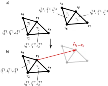
Repetition Pattern (RP) encoding mechanism reduces the filesize by leveraging the presence of repetition patterns within the mesh: isometric facets are not encoded separately but as translations of a unique facet. Several facets can even be encoded through the translation of a multiple facets mesh, as illustrated inFig. 2.
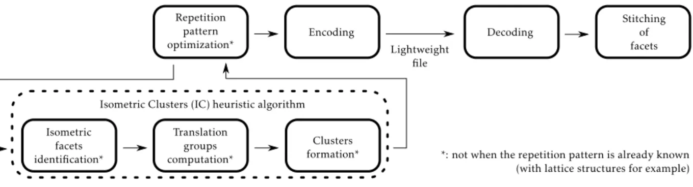
In order to exploit these two size-reducing mechanisms, an encoding and decoding framework is proposed and illustrated
inFig. 3. First, the optimization problem associated with the VI
and RP mechanisms, formalized in Section 4.1, is resolved by
Fig. 2. Repetition Pattern (RP) encoding mechanism exploiting the isometric
properties of facets.
a new heuristic algorithm run during the RP optimization step. The interest of using a heuristic is to provide a sub-optimal but good solution in a reasonable amount of time (see Section4.3). This step is only required when the repetition pattern of the geometry is unknown, in case of a support structure for example (see Sections5.4and5.5). However, in case of a lattice structure generated by the 3D repetition of a unit-cell mesh, the pattern is imposed by the lattice generation. This pattern is a priori known and can therefore directly be exploited during the encoding step in order to reduce the file size through the VI and RP encoding mechanisms. Similarly, if the mesh has been obtained from a CAD model on which patterns have been identified prior to its tessel-lation, then this information can directly be exploited within the proposed framework, and some steps might be bypassed.
Once the geometry encoded, the resulting file can be easily stored or transmitted to another party, as its size is greatly re-duced. At reception, the file can be decoded through the adapted procedure (associated with the encoding strategy). Because of the RP mechanism, a final step of facets stitching is required in order to ensure the watertightness of the mesh (see details in Sec-tion5). This operation is the same as the one required when im-porting an STL file, and will therefore not be extensively detailed in this article that mostly focuses on the encoding steps. How-ever, as discussed in the conclusion, some of the PDP steps (e.g. slicing or geometry healing) could also benefit from this approach without having to decompress the whole part geometry. In this case, time-consuming operations could be performed just once and the resulting geometries could then be repeated according to the characteristics of the identified patterns.
4. Identification of repetition patterns in facet meshes
This section details the algorithm used to identify one of the most promising repetition patterns in a meshM, i.e. one that best reduces the encoding file weight. This identification results from the resolution of an optimization problem that tries to minimize the weight
w
(M, κ
) of the file resulting from the encoding ofM according to an encoding strategy
κ
. As there exists a huge amount of admissible repetition patterns decompositions when considering AM parts, a heuristic algorithm is proposed to solve this problem, and its efficiency is demonstrated in Section5.Fig. 3. Encoding and decoding framework used to generate easily transferable lightweight mesh files.
4.1. Mesh decomposition problem formalization
Let us noteF the set of all facets f of the meshM, and S a subset ofF, i.e. S
⊂
F. Encoding S according to a certain encoding strategyκ
generates a certain file weightw
κS that contributes to the resulting overall file weight. From these definitions, the encoding optimization problem can be defined as a Weighted Exact Cover (WEC) problem, where the objective is to find a decomposition ofFinto subsets, minimizing the overall encoding cost function, i.e. the sum of the file weights of the encoded sub-sets. This can be written as the following Integer Linear Problem (ILP), where each subset is associated with a boolean activation variable xS defining whether or not S is part of the solution: Minimizew
(M, κ
)=
∑
S∈ASw
κ S.
xS (1a) subject to∀
f∈
F,
∑
S∈AS:f∈S xS=
1 (1b) xS∈ {
0,
1}
(1c)whereAScorresponds to the partition ofF (i.e. the set of all the possible subsets ofF). The cardinality ofAS (i.e.
|
AS| =
2|F|) can be very large when considering AM parts potentially defined by hundreds of thousands of facets. The exact nature of the problem is formalized by Eq.(1b), which constrains each facet ofF to be contained by only one subset of the solution.The WEC problem has been extensively studied, and has been proven to be NP-complete [23]. One of the most famous strategy to solve this problem is the Dancing Link (DL) algorithm [24]. It is a simple greedy recursive back-tracking algorithm allowing to efficiently identify all the solutions of the WEC problem, i.e. all the divisions of the universe U (that isF in the present case) into disjoint subsets covering all the elements of U. The concept is straight forward: first, a subset S is selected to be part of the first solution. Then all the subsets containing at least one facet of S are removed from the list of selectable subsets, in order to ensure the exact nature of the solution (i.e. with disjoint subsets). By identifying the facets of the universe that are not already contained in one of the subsets of the solution, a sub-universe
U′
⊂
U is obtained on which the DL algorithm can recursively
be executed. The main issue with the DL algorithm is that it requires to list all the possible subsets ofF, and this enumeration of 2|F|
subsets can be very time-consuming. Therefore, in this article, a heuristic based on 3 considerations has been developed to solve the identified WEC problem, and its execution is detailed in Section4.3.
4.2. Exploitation of the RP encoding mechanism
In order to best exploit the previously introduced RP encoding mechanism (and thus find out a decomposition ofM into dis-joint subsets that reduces the overall encoding file weight), the isometries between the facets of a subset S
⊂
Fcan be exploited, reducing its encoding weight.In this article, only the case of isometries by translation be-tween the facets is considered. Two facets (f
,
f′)
∈
F2 areisometric by translation if it exists a translation tf→f ′(associated with a 3D vector
⃗
tf→f ′) by which f′is the image of f and so that f′
=
tf→f ′(f ). This implies that the two facets have the same angles, but also the same edge lengths, the same normal and the same area. The benefit of only considering isometries by translation instead of all the similarities (such as rotation and scaling) is that no rounding error is introduced. Indeed, the translation of a point by any vector can be obtained only through addition and subtraction, whereas is it not the case for the other similarities for which inaccuracies can be introduced depending on the angle of rotation or the scaling factor.
Let us define an isometric subset as a subset I
⊂
F in which all the facets are isometric by translation. Let us define the facet translation groupΓIf associated with a facet f
∈
I as the set of all translations transforming f into another facet of I:ΓI
f
= {
tf→f ′:
f ′∈
I}
(2)Let us also define the translation groupΓIassociated with the isometric subset I as the union of the facet translation groups associated with each facet f
∈
I:ΓI
=
⋃
f∈IΓI
f (3)
Because of the two size-reducing mechanisms identified in Section3(VI and RP mechanisms), one particular case for S is of interest to compute its encoding weight: the case where S can be written as the Cartesian product of a set of facets FS
⊂
Fand a set of 3D translation vectors TSwith⃗
0∈
TS. This is noted S=
FS×
TS. This means that if the translation t (associated with each vector⃗
t∈
TS) is applied to each facet f∈
FS, each facet of S is obtained only once.Finally, let us define VSthe set of non-redundant vertices of S. Therefore, the computation of the encoding cost of a subset S of facets falls into two cases:
•
if S can be written as FS×
TS:w
κ S=
w
Vκ.|
VS| +
w
κF.|
FS| +
w
κT.|
TS| +
w
csteκ (4a)•
otherwise,w
κ S=
w
Vκ.|
VS| +
w
κF.|
S| +
w
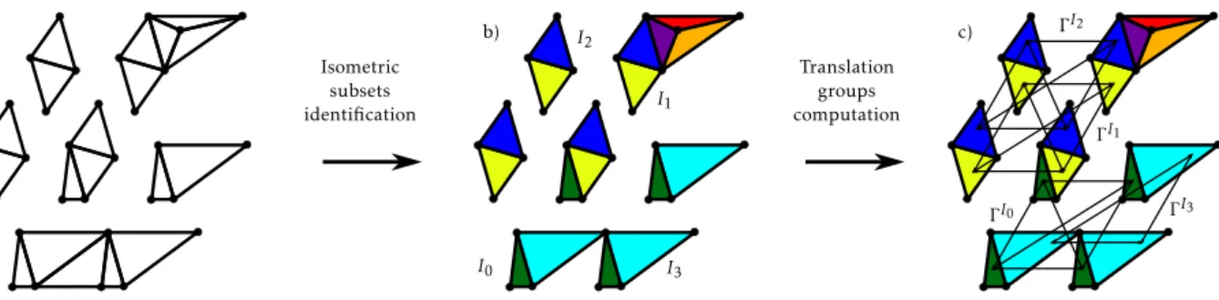
csteκ (4b)Fig. 4. Isometric subsets identification (b) and translation groups computation (c) on a facet mesh (a) : first two steps of the Isometric Clusters (IC) heuristic
algorithm.
As it will be discussed in Section5.3, the coefficients
w
κV,w
κF,w
κT and
w
csteκ depend on the adopted encoding strategyκ
and file format in which the information is encoded. Because encoding a facet is usually more expensive than encoding a translation (w
κF≥
w
κT), encoding Cartesian product based subsets of facets is more beneficial than encoding regular subsets. This is particularly in-teresting to reduce the resulting file size. These two functions are finalizing the previously introduced ILP definition (Section4.1).
4.3. Heuristic resolution
To solve the ILP associated with the RP optimization step, the
Isometric Clusters (IC) heuristic algorithm has been developed. It
is composed of three consecutive stages, namely the isometric subsets identification, the translation group computation and the clusters formation, which executions are detailed in the next paragraphs. In comparison to using a metaheuristic algorithm, the IC heuristic produces a good solution almost instantly. The computation time is especially important for such an encoding problem for which it should not exceed a few seconds.
4.3.1. Isometric subsets identification
In the first stage of the IC heuristic algorithm, the isometric facets are grouped together through the creation of isometric subsets. This is illustrated inFig. 4, where each isometric subset is identified by a specific color. In order to speed up the association of facets, a hash table data structure is used. Through the defi-nition of a hash function invariant by translation, i.e. a function outputting the same value for two facets isometric by translation (this value being the common hash key of the considered facets), a hash table data structure enables to group isometric facets together with a linear O(n) worst-case complexity (compared to the quadratic O(n2) complexity of a one-to-one comparison). For
example, the same technique is employed to reduce the time of triangles stitching during a mesh reconstruction operation [25]. In our implementation, this hash key is defined as the concatenation of the edge vectors coordinates of the facet, starting from the longest edge and contouring the facet according to its orientation, as illustrated in Fig. 5. This hash function is adapted for any oriented polygon regardless of its number of edges. Thus, two facets are guaranteed to have the same hash key if and only if they are isometric by translation. In the rest of this paper, the hash key corresponding to a facet f will be denoted as H1(f )
4.3.2. Translation groups computation
Before combining subsets together so as to form facet clusters, each isometric subset I must also be associated with a specific hash key. This second hash function denoted H2, must associate
the same key to isometric subsets demonstrating the same rep-etition pattern, so as to clusterize them together. To do so, in our implementation, a reference facet fI
ref is first selected for each
Fig. 5. Hash function for a fast identification of isometric facets.
isometric subset I. The hash key associated with I is then defined as the facet translation group corresponding to fI
ref:
H2(I)
=
ΓfII ref(5) Let us consider I0and I1two isometric subsets demonstrating
the same repetition pattern. To ensure that H2 associates the
same key to I0 and I1, their respective reference facet f I0
ref and
frefI1 must be identically located (with respect to I0 and I1) in
order to have the same facet translation group ΓI0 frefI0
=
ΓI1 frefI1. Therefore, in our implementation, the reference facet frefI of each isometric subset I is defined as its left-most facet (i.e. having the vertex with the smallest x-coordinate. In case of equality, the disambiguation is done on the vertices y-coordinates, and then on the z-coordinates).Let us now consider any isometric subset I. For the identi-fication of the translation group ΓI
frefI , each facet f
∈
I must be associated with a reference point rf, identically located with respect to f . Considering two facets (f0,
f1)∈
I2, the associatedreference points rf1and rf0must ensure that f1
=
tf0→f1(f0) wherethe associated 3D translation vector of t is
⃗
tf0→f1=
rf1−
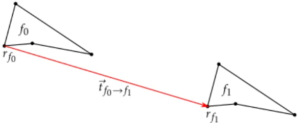
rf0. The use of the facet barycenter could lead to inconvenient approx-imations, therefore in our implementation, the left-most vertex (i.e. with the smallest x-coordinate) of each facet is considered as a reference point, as illustrated inFig. 6. Here again, in case of equality, the disambiguation is performed on the y-coordinates, and then on the z-coordinates).4.3.3. Clusters formation
Once the first two stages of the IC algorithm are executed (as illustrated inFig. 4), the isometric subsets are grouped according
Fig. 6. Reference points rf0 and rf1 used for the computation of the translation
vector⃗tf
0→f1.
to their translations groupΓI: isometric subsets with the same translation group are joined together in a so-called isometric
cluster. Then, the IC heuristic algorithm decomposes each cluster,
according to the three following considerations (Fig. 7):
•
Identical isometric subsets: if a cluster contains severaliso-metric subsets (i.e. if two or more isoiso-metric subsets have identical translation groups), it is beneficial to encode them together, as the repetition of a generating mesh by a set of translations. In that case, the generating mesh contains one facet of each isometric subset, and all of these facets have the same facet translation group (defining the repetition pattern of the generating mesh).Fig. 7.d1 to g1 illustrate this process.
•
Isolated isometric subset: if an isometric subset I does nothave any counterpart with the same translation group ΓI (i.e. is the only item of its cluster), but contains more than one facet, it is beneficial to encode this subset as the repe-tition of one of its facets f0by its own translation groupΓf0I. This is illustrated inFig. 7.d2 and e2.
•
Mono-facet subsets: all the isometric subsets with only onefacet can be encoded together within a single mesh in order to benefit from the Vertex Indexing (VI) mechanism (see
Fig. 7.d3 and e3).
The pseudo-code of algorithm1details the execution of the IC heuristic algorithm. Using this heuristic, all the facets of the initial
mesh are encoded only once. Indeed, each facet within the initial mesh belongs exclusively either to a multiple facets isometric subset, or to a mono-facet subset.
Let us define n
= |
F|
so as to compute the time complexity of the IC algorithm. Thanks to the definition of the hash functionH1 and the use of a hash table data structure, the regroupment
of the facets ofF into isometric subsets is realized with a linear time complexity O(n). For each isometric subset I, the complexity of the reference facet identification is linear (i.e. in O(kI), where
kI
= |
I| ≤
n), and the same applies to the computation ofH2(I). This ultimately leads to a linear complexity of the isometric
subsets regroupment into isometric clusters. Finally, the last steps of the IC algorithm, which corresponds to the actual encoding of the repetition pattern, are also realized in linear time. Indeed, the translation group associated to each isometric subset refer-ence facetΓI
fI ref
has been computed for the calculation of H2(I).
Consequently, the overall time complexity of the IC algorithm is
O(n).
Algorithm 1 Isometric Clusters heuristic algorithm Require: F: list of facets
AI
←
groupF by f↦−→
H1(f )G
←
group AIby I↦−→
H2(I)=
ΓfII reffor all isometric cluster c
∈
G do Γc←
ΓI0frefI0 where I0is first element of c
for all isometric subset I
∈
c do Mc←
add fIref
end for
encode (Mc
,
Γc)end for
5. Implementation and results
In order to demonstrate the efficiency of the proposed heuris-tic algorithm to solve the file weight optimization problem identi-fied in Section 4.1, three geometries presenting repetition
patterns are encoded according to different encoding strate-gies (
κ
). The resulting file sizes are compared to the ones of state-of-the-art approaches such as the OpenCTM format (a com-pression file format and library created by an open-source project) implemented in the MeshLab software and the compression algorithm proposed by Alliez et al. [26]. Because the encoding precision of each strategy is different, some are more efficient than others in generating lighter files. The various encoding precisions are discussed in this section, along with the assets and efficiency of each approach.5.1. Quantization and additive manufacturing
In a 3D geometry file, many objects such as points or vectors must be encoded as floating-points. Two types of encodings can be distinguished: loss-less (ensuring that the decoding of any fi-nite floating-point produces exactly the same floating-point with all the same digits) and lossy encodings (producing a close but not necessarily identical floating-point at decoding).
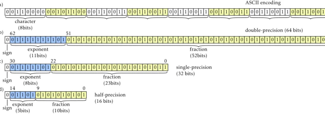
In case of an ASCII encoding, any finite floating-point can be encoded in a loss-less manner. In this case, all the digits from both the integer and the decimal part of any floating-point are represented by ASCII characters. Thus, the more precise the floating-point needs to be, the longest the ASCII chain is. In case of a binary encoding, only a finite number of floating-points can be encoded. The loss-less nature of the encoding therefore depends on the floating-points to encode and on its precision. Three main encoding precisions are usually considered, based on the IEEE 754-2008 standard: the half, single and double-precision formats, requiring respectively 16, 32 and 64 bits to encode a floating-point [27]. For each of these approaches, the resulting code is divided into 3 sections: the sign, the exponent and the fraction part (as illustrated byFig. 8). In all cases, only a finite number of floating-points can be encoded (respectively 216, 232and 264): this
is called floating-point quantization.
In this article, the encoded geometries used for performance evaluation are a lattice structure, a support structure and a static mixer, all designed for AM production. Assuming the geometry coordinates are defined in mm, it is admitted that a precision of 10−3mm is sufficient. Though large AM machines are emerging,
the common size of a printing platform is 250 mm
×
250 mm. Let us thus consider that the coordinates of the mesh are lying between−
125 and 125. In the IEEE 754-2008 floating point format standard, the precision of the encoded number depends on its value: the bigger a number, the less precise its encoding. For example, a floating-point between 64 and 128 will be encoded with a 2−4=
0.
0625 precision with the half-precision standard,and with a 2−17
≈
0.
000008 precision with the single-precisionstandard. Therefore, the half-precision quantization scheme does not meet the 10−3mm constraint imposed by the AM process,
but the single-precision standard does and this is the one that should be privileged for AM applications. However, in this paper, encodings with the half-precision format will be realized in order to make some fair comparisons with the algorithm proposed by Alliez et al. [26].
In the framework ofFig. 3, the floating-points quantization must be performed before the isometric facets identification, in order to maximize the compression rate of the heuristic algo-rithm. Indeed, two facets can be isometric after quantization even if they were not before this operation.
5.2. Implementation of the RP encoding mechanism
The RP mechanism has been implemented and tested follow-ing three encodfollow-ing strategies (
κ
) introduced in the next para-graphs: RP-AMF, RP-32 and RP-16. The RP-AMF one directly ex-ploits the formalism of the AMF (Additive Manufacturing File)format. AMF is a standard specification developed specifically for AM applications. Its creation was motivated by the need to supplement the low-information and inefficient formats still in use within the AM domain (i.e. STL and OBJ). Among other features, an AMF file can associate with a mesh-based part various pieces of information, regarding its color, texture, 3D orientation and so on. Moreover, it natively includes a VI mechanism in order to reduce the resulting file size. Finally, it can encapsulate
constellations containing several instances of the same part. Here,
an instance refers to an object (containing a mesh) through an object id (seeAppendix B) and includes a set of translations and rotations locating a copy of the object in the 3D space. The aim of the AMF instance objects was originally to locate several iden-tical parts onto the build platform, without needing to duplicate vertices and facets of the mesh.
The same VI and RP mechanisms can also be found in the emerging 3MF file format, also dedicated to Additive Manufac-turing applications. In this format, elements called components are equivalent to the constellations objects of the AMF standard, and are used to repeat several instances of the same triangle mesh. Because of these similar entities, the proposed approach can seamlessly be applied with the AMF or 3MF specifications, and would demonstrate the same performances. Therefore, it has been chosen in this work to exploit only the AMF standard specification to develop the RP-AMF file format.
RP-AMF encoding strategy directly exploits the RP mechanism
and AMF standard to reduce the overall size of AMF files while avoiding multiple definitions of highly repeated geometries. Let us consider a part with a specific feature repeated several times. Using the RP-AMF encoding strategy, the mesh corresponding to this feature is encoded only once, and each repetition of this feature is encoded as an instance of the previous mesh. The rest of the part facets is encoded into another independent mesh. This encoding strategy is not restricted to one-feature Repetition Patterns only, and this example can easily be extended to parts presenting multiple repeated features. The RP-AMF en-coding strategy preserves the AMF formalism: ASCII enen-coding, standard tags, vertices collection and triangles indices structure. The *.amf extension is also preserved, ensuring that any software able to open an AMF file format is also able to open an RP-AMF file. At opening, all the individual meshes are repeated according to its corresponding encoded instances. However, as intended by the AMF standard, each fragment repetition will be considered as an independent part on the building platform. Therefore, a stitch-ing operation is required in order to ensure the watertightness of the opened mesh. This is similar to what is needed when import-ing an STL file. Indeed, the overall geometry beimport-ing composed of several meshes, the points at the border of each mesh are gener-ally duplicated within the definition of another mesh. The aim of the stitching step is thus to identify and merge duplicate vertices and edges, thus connecting neighboring triangles. By preserving the AMF formalism, the RP-AMF exchange is instantly exploitable, without any software modification required. However, the AMF formalism is not a concise 3D geometry description, and thus creates heavy files in comparison to other formalisms. Indeed, it is an ASCII description, employing redundant tags, separators as well as other artifacts.
RP-32 and RP-16 encoding strategies make use of a binary
format to further reduce the size of the files. These new formats stand out from the RP-AMF because the encoding of each floating-point is realized through an IEEE 754-2008 floating floating-point format standard. Thus two versions of this format must be distinguished: the RP-32, using the single-precision standard, and the RP-16, using the half-precision standard. The structure of this format is similar to the one of the AMF file format, in so that it implements a 3-blocks VI mechanism. For each mesh, a collection of points is
Fig. 8. IEEE 754-2008 standard: half (a), single (b) and double (c)-precision floating point formats.
defined, followed by a collection of point indices triplets (each triplet representing a triangle): these two blocks are encapsulat-ing the VI mechanism. The last block consists of a collection of 3D vectors locating the multiple instances of the mesh in the 3D space. The overall part geometry is thus defined by a succession of block triplets. To further lighten the file, the unnecessary tags of the AMF encoding have been removed: no separation between floating points are required since the bit length of each encoded number is constant in binary. Only a separation between a block and the next is required, and is realized by a line jump.
5.3. Cost coefficients
In Section4.1, the ILP governing the RP optimization has been identified and formalized. Eqs. (4a) and (4b)reveal the use of cost coefficients which values depend upon the adopted encoding strategy (
κ
).Table 1summarizes the coefficients of the file for-mats considered in this article (for triangle meshes only). Because the RP-AMF is an ASCII based formalism, the number of bits used to encode each vertex, facet and translation (respectivelyw
Vκ,w
κF andw
Tκ) is not constant. Indeed, the number of ASCII characters used depends upon the number of digits of the floating point (or the integer in the case of vertex indices for the facet definitions). However, because the AMF format uses encompassing tags for defining each of these objects, an average number of characters can be given, around which the variations are small (considering the process precision requirements of 10−3mm as discussed inSection5.1). For the binary formats, the number of octets used to encode a floating-point is constant (because it is a binary encoding) and is only defined by the IEEE 754-2008 standard employed (4 octets by floating point for the single-precision in RP-32 and 2 octets by floating point for the half-precision in RP-16). However, looking at the encoding cost per facet
w
κF, the number of octets used to encode an integer is the same for both versions of the binary format since the chosen binary precision must not impact the number of vertices that can be encoded. Indeed, 4 octets are used to encode each vertex index ensuring that each positive integer between 0 and 232≈
4 294 967 295 can be encoded. These costs are also much lower because the unnecessary tags of the AMF have been removed with the use of binary formalism.5.4. Experimentation on lattice structures with known RP
This section illustrates how the proposed RP encoding frame-work can be used to reduce the file size when storing geometries for which the repetition patterns are already known. This is the case when the software used to model the part is also the one
Fig. 9. Full lattice structure of the Stanford Bunny (a) with repeated features
mesh (blue) and residual mesh (red), and repetition pattern (b). (For interpre-tation of the references to color in this figure legend, the reader is referred to the web version of this article.)
Table 1
Cost coefficients associated to each file formatκfor the RP optimization. File format (κ) wκV (in octets) wκF (in octets) wκT(in octets)
RP-AMF ≈77(±9) ≈64(±14) ≈97(±9)
RP-32 12 12 12
RP-16 6 12 6
encoding its geometry into an exchange file. In this case, the first framework steps of pattern identification (illustrated inFig. 3 with an asterisk) can be bypassed.
To demonstrate the efficiency of the proposed framework, the compression of a lattice structure generated within the famous Stanford Bunny has been realized (Fig. 9). This lattice structure has been generated through the repetition of a simple BCC unit cell of 4 mm side. The border unit cells have been trimmed to the envelope of the bunny, resulting in a total of 1330 complete unit cells, each one composed of 154 triangles (using the lattice meshing approach of Chougrani et al. [28]), and a residual mesh composed of 312 834 triangles (i.e. 517 654 triangles total). In the case of a known RP, the geometry is initially divided into two meshes: a repeated features mesh (in blue onFig. 9.a), associat-ing the facets of each repeated feature with the correspondassociat-ing repetition pattern (Fig. 9.b), and a residual mesh, gathering all the individual facets (in red onFig. 9.a). Only the repeated feature mesh benefits from the use of the proposed repetition encoding framework. Since the residual mesh does not present any repe-tition pattern, its encoding through the proposed framework is generally not optimal, but is necessary to complete the overall part geometry during the decoding step.
Table 2
Compressed file sizes for a known repetition pattern part (Stanford Bunny lattice structure).
File format (κ) Bits per Lattice structure File
floating 133 440 vertices size
point Unzipped Zipped reduct.
AMF 8–48 (ASCII) 76 511 Ko 4564 Ko
RP-AMF 8–48 (ASCII) 32 774 Ko 3062 Ko −33%
OpenCTM 32 (binary) n/a 3524 Ko
RP-32 32 (binary) 1773 Ko 1316 Ko −63%
Alliez et al. [26] 16 (binary) n/a 933 Ko
RP-16 16 (binary) 872 Ko 646 Ko −31%
Six encoding strategies have been experimented: the classical AMF format, the newly developed variation of this format exploit-ing RP and encoded in ASCII (RP-AMF), with a sexploit-ingle-precision binary format (RP-16) and with a half-precision binary format (RP-32), the OpenCTM format (a compression file format and library created from an open-source project) implemented in the MeshLab software and a compression algorithm proposed by Al-liez et al. [26]. Because the OpenCTM and the format proposed by Alliez et al. are both implementing binary-wise data compression schemes (hence the ‘‘n/a’’ abbreviations in the ‘‘unzipped’’ column of the following result tables), the zipped version of the other formats is also considered.
The file sizes resulting from these various encoding approaches are summarized in Table 2 along with the file size reductions obtained comparing same precision encodings. From these re-sults, RP-based formats are demonstrating lower file sizes, for both their unzipped and zipped versions, with file size reductions reaching
−
63%. These results well illustrate the interest of the proposed framework with respect to state-of-the-art approaches.5.5. Experimentation on support structures with unknown RP
Beyond lattice structures, the proposed framework can also be used to efficiently compress any 3D shape presenting repetition patterns. Such repeated geometries are more common in AM than in other manufacturing fields due to the design freedom permit-ted by the ‘‘layer-by-layer’’ approach, and support structures are great examples of such geometries. Generated after the design of the part and before the slicing step, they usually are regularly per-forated with rhombus-shaped holes, in order to ensure the good evacuation of the powder once the part fabrication is completed (with the Laser Beam Melting technology in particular).
Therefore, the efficiency of the proposed framework has been demonstrated with the compression of a support structure geom-etry (Fig. 10) and a static mixer geometry also presenting several repeated features (Fig. 11). The considered encoding strategies and file formats are the same as the ones used for the compres-sion of the lattice structure in Section5.4. Initially composed of 13 196 and 21 610 triangles respectively, the support structure and the static mixer are decomposed respectively into 69 and 71 RP once the IC heuristic algorithm is executed. However, these patterns are particularly different: most of the support structure generating meshes are composed of less than 10 facets repeated up to 440 times, whereas the biggest generating mesh of the static mixer contains 317 triangles duplicated only twice. The support structure presents also more repeated facets since its residual mesh contains only 1629 triangles compared to 14 042 facets for the one of the static mixer.
Similarly to the lattice structure, the file sizes resulting from the proposed encoding strategies of these two test cases are lower than the ones of the files generated by the other strategies
(Table 3). The file size reduction ratios are also indicating the
Fig. 10. Support structure test case: initial mesh and supported part (a), mesh
decomposed after repetition pattern encoding (b) and its generating meshes (c).
Fig. 11. Static mixer test case: initial mesh (a), mesh decomposed after
repetition patterns encoding (b) and its generating meshes (c).
same trend. Comparing the various RP-based encoding strategies between the support structure and the static mixer, the file size reduction ratios are similar, even though the number of repetition patterns (and the generating mesh facet counts) are different between the two geometries.
Table 3
Compressed file sizes for the two test cases (support structure and static mixer) with unknown RP.
File format (κ) Bits per Support structure File Static mixer File
floating 5721 vertices size 10 791 vertices size
point Unzipped Zipped reductions Unzipped Zipped reductions
AMF 8–48 (ASCII) 1827 Ko 89 Ko 3180 Ko 167 Ko
RP-AMF 8–48 (ASCII) 346 Ko 15 Ko −83% 389 Ko 26 Ko −84%
OpenCTM 32 (binary) n/a 42 Ko n/a 75 Ko
RP-32 32 (binary) 53 Ko 9 Ko −79% 31 Ko 14 Ko −81%
Alliez et al. [26] 16 (binary) n/a 20.2 Ko n/a 28.1 Ko
RP-16 16 (binary) 27 Ko 6 Ko −70% 16 Ko 9 Ko −68%
Table 4
IC heuristic algorithm computation times for the two considered test cases.
Framework steps Support Static
structure mixer
Isometric subsets identification 169 ms 372 ms
Translation groups computation 390 ms 576 ms
Clusters formation 18 409 ms 556 ms
Table 5
Overall encoding times for the different encoding strategies considered.
File format (κ) Bits per Lattice Support Static
floating structure structure mixer
point
AMF 8–48 (ASCII) 9 s 1 s 1 s
RP-AMF 8–48 (ASCII) 13 s 25 s 5 s
OpenCTM 32 (binary) 11 s 4 s 3 s
RP-32 32 (binary) 9 s 27 s 4 s
Alliez et al. [26] 16 (binary) 82 s 2 s 3 s
RP-16 16 (binary) 6 s 30 s 3 s
5.6. Encoding times comparison
One of the obstacles to the adoption of a compressed format is the encoding time taken to obtain the resulting files. In order to analyze computation time issues, the duration of each IC heuristic algorithm stage is first measured and the results are presented in
Table 4. In the case of a lattice structure, the IC heuristic algorithm
is not run as the RP is known a priori and can thus be directly exploited during the encoding step.
These results are illustrating the different behaviors that can arise from the execution of the IC algorithm on geometries with different unknown repetition patterns. For example, in the case of a mesh with a simple feature repeated a lot of times such as the one of the support structure, numerous isometric subsets must be clustered together, and the clusters formation is therefore the more time-consuming step. Inversely, when the part presents several complex features replicated only a few times like for the static mixer, the duration of the clusters formation step is considerably reduced.
To compare the speed of the proposed framework to the ones of the literature, the overall encoding times of the previous test cases have also been measured and listed inTable 5. On an indica-tive basis, the times to encode the three considered structures in AMF have also been added, though it does not include any optimization mechanism.
The computation time of the lattice structure encoding demon-strates the speed of the proposed framework regarding geome-tries for which the repetition pattern is known in advance. Indeed, for this particular test case, the compression algorithms of the literature (namely the Open CTM format, and the algorithm proposed by Alliez et al.) are presenting longer optimization times. However, in the case of geometries where the repetition pattern is not a priori known, such as the support structure and
the static mixer, the proposed framework optimization times are not competing with the literature algorithms.
Focusing on the RP-encodings results, though the lattice struc-ture is composed of more facets, its encoding is faster than the one of the support structure, since the RP optimization step does not need to be executed (Fig. 3).
However, comparing the results obtained with the RP-based encodings between the static mixer and the support structure, one can identify the longest time requirements for the latter. This can be explained by the difference between the two pattern structures (as detailed in Section5.5). Since the longest operation is the clusters formation, and since the pattern structure of the static mixer is composed of larger generating meshes with fewer repetitions than the ones of the support structure, its encoding is performed more rapidly. This corroborates with the results displayed inTable 4.
In conclusion, though the proposed framework performances are surpassing the ones of the literature algorithms in terms of compression rate, this comes at a small temporal cost. This cost can vary according to the prior knowledge of the repetition pat-terns, and according to its balance between the number of facets and the number of repetitions of each generating mesh. However, the order of magnitude of the RP-based encodings optimization durations are remaining reasonable, ergonomically speaking, for a compression encoding operation.
6. Conclusions and perspectives
This article has introduced a new framework for the file com-pression of faceted 3D geometries presenting repetition patterns. This approach diminishes the size of the 3D geometry file by encoding a repeated feature as one mesh and several repetitions of it, rather than encoding each similar mesh once. This frame-work is particularly suited for parts produced by AM machines and often presenting repetition patterns. It can straightforwardly be applied on geometries for which the repetition pattern is already known (such as lattice structures). But in the broader case, the geometry’s 3D mesh must first be decomposed into repeated submeshes, in order to ensure a high compression rate. The identification of repeated submeshes is performed by a new heuristic algorithm especially developed to solve the underlying NP-complete Weighted Exact Cover (WEC) problem.
The benefits of this framework have been demonstrated on three test cases and for several file encodings: a variation of the standard AMF format (the RP-AMF format), and a dedicated binary file format with different floating point precisions (the RP-32 and the RP-16 formats). By exploiting the numerical ob-jects included within the AMF standard definition, this work encourages its adoption within the AM community. The results of the three test cases have demonstrated both good compression rates and reasonably short computation times when compared to state-of-the-art approaches.
This work only takes advantage of the repetitions consisting of 3D translations. Other similarities could be exploited (such as ro-tation, scaling or symmetries) to further enhance the compression
rate. The identification algorithms for such patterns proposed by Shi et al. could therefore be employed [11]. However, en-coding circular repetition patterns, scaling or symmetries can lead to approximation errors, resulting in a non-watertight mesh. Furthermore, many AM parts (especially the ones with lattice structures features) mostly present translated pattern repetitions, which already makes the proposed framework useful.
To further increase the efficiency of the proposed framework, the computation time required for the RP optimization could be reduced. Indeed, the more time-consuming step of the IC heuris-tic algorithm has been identified, namely the clusters formation stage, and could be accelerated by using GPU parallelization for example. Moreover, to further decrease the encoding file sizes generated by the framework, the quality of the mesh decompo-sition obtained after the RP optimization step could be improved by implementing a more complex algorithm. Such an algorithm could for example benefit from a splitting operation applied on an isometric subset, in order to create a more efficient clustering. In the same intent, a multi-scale approach could also be developed to encode repetitions of repetition patterns (nested repetitions) within the resulting file.
Moreover, to further increase the compression ratio, the pro-posed framework could be coupled with another mesh descrip-tion encoding (such as the one of Alliez et al. [26]). Indeed, the RP mechanism is decomposing the part geometry into independent meshes to be encoded with or without repetition, and the encod-ing of each mesh can be more complex than the one employed in the RP formats (i.e. listing all the 3D points and then listing all the facets as triplets of point indexing). The RP mechanism is therefore a compression layer that can be coupled with any existing geometry compression approach.
Finally, not only the proposed repetition pattern encoding framework allows file size reductions, but it can also be ex-ploited at various steps of the Product Development Process (PDP), including process planning phases. For instance, the pro-posed framework could benefit to the slicing step, wherein the repetition patterns could be exploited without having to decom-press the whole part geometry. Indeed, knowing the elementary feature (that is repeated) and the locations of its various oc-currences, the slicing operation can be applied once, and the so computed trajectories can be repeated to match the other locations of the considered feature. More broadly, the preserva-tion and exploitapreserva-tion of part repetipreserva-tion patterns throughout the production workflow thus permits to optimize and speed up the end-to-end AM process.
Declaration of competing interest
The authors declare that they have no known competing finan-cial interests or personal relationships that could have appeared to influence the work reported in this paper.
Appendix A. AMF mesh formalism
<
?xml version=
"1.0">
<
amf unit=
"millimeter">
<
object id=
"1">
<
mesh>
<
vertices>
<
vertex>
<
coordinates>
<
x>1.2<
/x><
y>
5.6<
/y><
z>
3.468<
/z>
<
/coordinates>
<
/vertex>
. . .
<
/vertices>
<
volume>
<
triangle>
<
v1>
1<
/v1><
v2>
2<
/v2><
v3>
3<
/v3>
<
/triangle>
. . .
<
/volume>
<
/mesh>
<
/object>
<
/amf>
Appendix B. AMF constellation formalism
<
?xml version=
"1.0">
<
amf unit=
"millimeter">
<
object id=
"1">
. . .
<
/object>
<
constellation id=
"2">
<
instance objectid=
"1">
<
deltax>
5<
/deltax>
<
deltay>
10<
/deltay>
<
deltaz>
0.5<
/deltaz>
<
rx>
-10<
/rx>
<
ry>
10<
/ry>
<
rz>
180<
/rz>
. . .
<
/instance>
<
/constellation>
<
/amf>
References[1] Dilberoglu UM, Gharehpapagh B, Yaman U, Dolen M. The role of additive manufacturing in the era of industry 4.0. Procedia Manuf 2017;11:545–54.
[2] Jafari D, Wits WW. The utilization of selective laser melting technology on heat transfer devices for thermal energy conversion applications: A review. Renew Sustain Energy Rev 2018;91:420–42.
[3] Gao W, Zhang Y, Ramanujan D, Ramani K, Chen Y, Williams CB, Wang CC, Shin YC, Zhang S, Zavattieri PD. The status, challenges, and future of additive manufacturing in engineering. Comput Aided Des 2015;69:65–89.
[4] Shi K, Cai C, Wu Z, Yong J. Slicing and support structure generation for 3D printing directly on B-rep models. Vis Comput Ind Biomed Art 2019;2(1):3.
[5] Dixit T, Ghosh I. Review of micro- and mini-channel heat sinks and heat exchangers for single phase fluids. Renew Sustain Energy Rev 2015;41:1298–311.
[6] Qin Y, Qi Q, Scott PJ, Jiang X. Status, comparison, and future of the representations of additive manufacturing data. Comput Aided Des 2019.
[7] McMillan M, Jurg M, Leary M, Brandt M. Programmatic lattice generation for additive manufacture. Proc Technol 2015;20:178–84.
[8] Azman AH, Vignat F, Villeneuve F. Evaluating current CAD tools perfor-mances in the context of design for additive manufacturing, no 44. 2014, p. 1–7.
[9] Savio G, Meneghello R, Rosso S, Concheri G. 3D model representation and data exchange for additive manufacturing. In: von Schweinitz D, Ure B, editors. Kinderchirurgie. Berlin, Heidelberg: Springer Berlin Heidelberg; 2019, p. 412–21.
[10] Pauly M, Mitra NJ, Wallner J, Pottmann H, Guibas LJ. Discovering structural regularity in 3D geometry. 2008, p. 11.
[11] Shi Z, Alliez P, Desbrun M, Bao H, Huang J. Symmetry and orbit detection via Lie-Algebra voting. Comput Graph Forum 2016;35(5):217–27.
[12] Sipiran I, Gregor R, Schreck T. Approximate symmetry detection in partial 3D meshes. Comput Graph Forum 2014;33(7):131–40.
[13] Mellado N, Guennebaud G, Barla P, Reuter P, Schlick C. Growing least squares for the analysis of manifolds in scale-space. Comput Graph Forum 2012;31(5):1691–701.
[14] Biasotti S, Thompson EM, Barthe L, Berretti S, Giachetti A, Lejemble T, Mellado N, Moustakas K, Manolas I, Dimou D, Tortorici C, Velasco-Forero S, Werghi N, Polig M, Sorrentino G, Hermon S. SHREC’18 track: Recognition of geometric patterns over 3D models. 2018, p. 8.
[15] Nan L, Sharf A, Zhang H, Cohen-Or D, Chen B. SmartBoxes for interactive urban reconstruction. ACM Trans Graph 2010;29(4):1.
[16] Shen C-H, Huang S-S, Fu H, Hu S-M. Adaptive partitioning of urban facades. In: Proceedings of the 2011 SIGGRAPH Asia conference on - SA ’11. Hong Kong, China: ACM Press; 2011, p. 1.
[17] Yi C, Lu D, Xie Q, Liu S, Li H, Wei M, Wang J. Hierarchical tunnel modeling from 3D raw LiDAR point cloud. Comput Aided Des 2019;114:143–54.
[18] Maglo A, Lavoué G, Dupont F, Hudelot C. 3D mesh compression: Survey, comparisons, and emerging trends. ACM Comput Surv 2015;47(3):1–41.
[19] Steuben JC, Iliopoulos AP, Michopoulos JG. Implicit slicing for functionally tailored additive manufacturing. Comput Aided Des 2016;77:107–19.
[20] Lee KH, Woo H. Direct integration of reverse engineering and rapid prototyping. Comput Ind Eng 2000;38(1):21–38.
[21] Vaissier B, Pernot J-P, Chougrani L, Véron P. Genetic-algorithm based framework for lattice support structure optimization in additive manufacturing. Comput Aided Des 2019;110:11–23.
[22] Taubin G, Horn W, Lazarus F, Rossignac J. Geometry coding and VRML. Proc IEEE 1998;86(6):1228–43.
[23] Garey MR, Johnson DS. Computers and intractability: A guide to the theory of NP-completeness. W. H. Freeman and Company; 1979.
[24] Knuth DE. Dancing links. 2000,arXiv:cs/0011047.
[25] Skala V, Hrádek J, Kucha M. Hash function for triangular mesh reconstruction. 2009, p. 6.
[26] Alliez P, Desbrun M. Valence-driven connectivity encoding for 3D meshes. Comput Graph Forum 2001;20(3):480–9.
[27] IEEE standard for floating-point arithmetic 754-2019. IEEE; 2019, p. 16.
[28] Chougrani L, Pernot J-P, Véron P, Abed S. Lattice structure lightweight triangulation for additive manufacturing. Comput Aided Des 2017;90:95– 104.