HAL Id: hal-02420781
https://hal.archives-ouvertes.fr/hal-02420781
Submitted on 20 Dec 2019
HAL is a multi-disciplinary open access archive for the deposit and dissemination of sci-entific research documents, whether they are pub-lished or not. The documents may come from teaching and research institutions in France or abroad, or from public or private research centers.
L’archive ouverte pluridisciplinaire HAL, est destinée au dépôt et à la diffusion de documents scientifiques de niveau recherche, publiés ou non, émanant des établissements d’enseignement et de recherche français ou étrangers, des laboratoires publics ou privés.
Cuisson d’une pièce composite dans un four micro-onde
industriel : méthodologie pour la simulation
Yann Duplessis Kergomard, Erik Abenius, Hermine Tertrais, Anaïs
Barasinski, Francisco Chinesta, Laurent Dufort
To cite this version:
Yann Duplessis Kergomard, Erik Abenius, Hermine Tertrais, Anaïs Barasinski, Francisco Chinesta, et al.. Cuisson d’une pièce composite dans un four micro-onde industriel : méthodologie pour la simulation. 21ème Journées Nationales sur les Composites, École Nationale Supérieure d’Arts et Métiers (ENSAM) - Bordeaux, Jul 2019, Bordeaux, Talence, France. �hal-02420781�
1
Cuisson d'une pièce composite dans un four micro-onde industriel :
méthodologie pour la simulation
Composite part curing in industrial Micro-wave oven: simulation methodology
Yann Duplessis Kergomard1, Erik Abenius1, Hermine Tertrais2, Anaïs Barasinski2, Francisco Chinesta3 et
Laurent Dufort1
1 : CoE Composites Virtual Manufacturing ESI GROUP
Parc ICADE, 3 bis rue Saarinen, CS 50468, 94528 Rungis Cedex, France e-mail : [email protected], [email protected] et [email protected]
2 : Gem - Institut de Recherche en Génie Civil et Mécanique Ecole Centrale Nantes
1 Rue de la Noë, 44321 Nantes, France
e-mail : [email protected], [email protected]
3 : ESI Chair at PIMM ENSAM ParisTech
151 Boulevard de l’Hôpital, 75013 Paris, France e-mail : [email protected]
Résumé
Ce papier présente la méthodologie développée pour construire une plateforme de simulation spécifique pour le procédé de cuisson de pièces composites dans un four micro-onde industriel de type Hephaïstos©. La méthodologie est basée sur un couplage faible entre une suite de simulations, tout d’abord électromagnétique dans le four micro-onde contenant la pièce composite et son moule, suivi d’une simulation chimico-thermique de la cuisson de la pièce. Ces simulations ont été réalisées respectivement sur les solveurs industriels ESI CEM-Ones® et ESI PAM-COMPOSITES®. Dans un second temps, les résultats de ces simulations ont été utilisés pour construire une solution paramétrique du chauffage pouvant être utilisée pour effectuer de l’optimisation du cycle de chauffe micro-onde ou un contrôle du procédé en temps réel. Ces derniers demandent en effet des temps de calcul brefs, une adaptation à l’évolution de la courbe de puissance, ainsi qu’une prise en compte de l’historique de cuisson de la pièce.
Abstract
The paper presents a simulation methodology to predict the curing of composites inside an industrial micro-wave Hephaïstos© oven. The methodology is based on a weak coupling method which chains an electromagnetic simulation of the MW oven containing the composite part and a heating-curing simulation of the composite part. These simulations respectively run with the industrial softwares CEM One® and PAM-COMPOSITES® from ESI. In a second step, these simulations are used to build a parametric solution to address magnetron optimization strategy or real-time process control issues.
Mots Clés : Micro-onde, cuisson, simulation, solution paramétrique Keywords : Micro-wave, curing, simulation, parametric solution
1. Introduction
The aeronautic and the automotive industries challenge more and more the manufacturing process of composite parts to reach the metallic standard in term of cost and time productions. Micro-Wave (MW) technology could be a good candidate to reduce both the energy consumption and the process time window during the heating steps.
Conventional heating processing methods for these parts usually involve the application of heat to the material by convection heating of the tool and composite in an oven
(pressurized/non-2
pressurized), or conductive heating of mold/platens through heating elements. Conversely to these traditional heating methods which depend on surface heat transfer, microwave (MW) technology relies on volumetric heating. Thermal energy is transferred through electromagnetic fields to materials that can absorb it at specific frequencies.
Volumetric heating enables better process temperature control [1] and less overall energy use, which can result in shorter processing cycles. The energy efficiency of the process is maximized as the volumetric heating occurs directly in the part to be processed, and no energy is wasted by heating the surrounding air or tool. These virtues of the MW technology have attracted interest in developing the method and adopting it to produce thermoset as well as thermoplastic composite materials.
Substantial time and energy benefits have been reported [2, 3]. The shorter cycle is possible as the microwave oven requires minimal ramp-up to set point temperature and the process has less tooling-driven thermal lag. Further, when the oven shuts off, there is no cool-down of the oven itself. Furthermore, comparable mechanical properties are shown between parts made with the MW technology and parts made with a traditional curing system (autoclave in the case of [4]).
The main drawback of this technology today is that the physics involved in the conversion of electromagnetic (EM) energy to thermal energy (heating) [1] is not entirely understood and controlled. The final aim of the SIMUTOOL project is to offer a modelling and simulation toolset of the MW heating process to the composites industry that does not exist today.
The paper first presents a chaining simulation based on a weak coupling method between an electromagnetic (EM) simulation inside the cavity of the oven, containing the composite and the mold parts, and a heating curing simulation of the composite part. The objective of this main part is to model the interactions of the MW field with the composite material and to describe how the local heat transfer mechanisms contribute to the overall heating of the produced part. These simulations are respectively performed with the industrial softwares CEM One® and PAM-COMPOSITES® from ESI [5-6].
However, while these simulations give relevant information on the process during its design, the CPU time to run them can be counted by hours or even days for large industrial cases. Thus, only few case-scenarios can be run, and this procedure can’t be used for process optimization (power cycle optimization for instance) nor for real-time control in operation. A parametric solution procedure is then proposed to target these goals.
After a brief presentation of the process, the global workflow chaining the electromagnetic (EM) model and the heating-curing simulation is presented. The parametric solution procedure is then briefly introduced, and last, some results are presented on a test case.
2. Process description
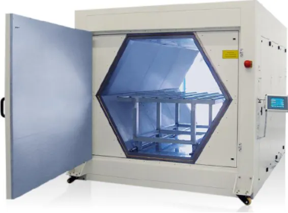
The experiment results shown in this paper were performed with the micro-wave oven of TWI, partner of the project, which is a Hephaïstos© oven VHM 100/100 produced by Weiss Technik. As shown on Fig. 1 the oven cavity has a hexagonal shape, with characteristic size of circa 1m x 1m (diameter and depth). Microwaves are produced by twelve magnetrons placed around the cavity with a characteristic frequency of 2.45 GHz. The maximum power of the oven is 10.2kW. The mold and the composite part are positioned on a metallic bench in the oven. The mold, produced by the SIMUTOOL partner Loiretech, is composed of a material transparent to MW but coated in its interior surface by an absorbent layer.
3
Fig. 1. Hexagonal-shaped Hephaïstos© VHM 100/100 microwave oven
3. Global offline simulation workflow
The first difficulty to simulate efficiently the coupled electromagnetic (EM) / thermo-chemical problem is the large separation of scales between the phenomena occurring in the oven cave and the ones occurring in the composite part. Indeed, in one side, the characteristics dimension of the oven cavity is of meter large, while in other side the ply thickness is of hundreds of micro-meters, and the distance between fibres are of micro-meters. The second challenge concerns the high-resolution description of the electromagnetic and thermal fields in an industrial size composite part.
To be able to capture all the important phenomena and to control efficiently the curing of the composite, a multi-scale simulation approach will be performed with a weak coupling approach, each problem being solved separately. The coupled quantities are exchanged at the end of each stage and inserted in the equations of the other problem. This method offers less accuracy compared to the strong coupling. Nevertheless, the weak coupling features the benefit to be faster on the various sub problems compared to the complete system and can be performed thanks to specialized solver to each sub problem. The electromagnetic material properties are assumed to be temperature independent with the chosen approach. It was shown during the project that the reached temperature levels only introduce a variation lower than 10%, making this first order approximation fully reasonable. This method doesn’t fix directly the changing of scale issue between the oven domain and the laminated composite domain, but thanks to suitable coupling equation or methodology, these specific problems can be handled.
Thus, the workflow simulation in the project consists of a weak coupling simulation between three different numerical problems which are:
1. A macro-scale EM simulation of the Micro-Wave Hephaïstos© oven, considering the twelve magnetrons around the oven, as the bench and an equivalent homogenized mold/composite part inside the oven. The problem is solved thanks to the ESI CEM One Solution® and is more described in section 3.1.
2. A micro-scale EM simulation inside the mold and the composite parts to capture the local phenomena, especially through the thickness with all the interfaces met by the EM waves. The EM boundary conditions are applied to the problem considering the EM macro-scale results coming from the previous stage.
4
3. A meso-scale thermo-chemical simulation inside the mold and the composite part to simulate the heating and curing history of the composite during the process. The problem is solved thanks to the ESI PAM-COMPOSITES® tools. The heating power sources are induced by the local electromagnetic fields and are calculated from the results of the previous stage. This stage is more described in section 3.2.
In this paper, we don’t focus on the EM micro-scale simulation (step 2), but rather on the chaining between EM simulation at the oven scale and thermo-chemical simulation for the curing. Thus, for the purpose of this paper , only a direct chaining between step 1 and step 3 will be considered. More details on the step 2 can be found in [8-9]. Considering the size of the oven and the available cluster computer resources, it was shown that a mesh size of 1mm could be reached. If possible burning issue due to too highly localized EM heating power at the interfaces is not considered in a first instance, as far as the smallest characteristic length of the composite (at the right considered scale) is greater than 1 mm, skipping the step 2 might be reasonable. However, with a bigger oven (a VHM 180/300 for instance which is 5 times bigger), or with a laminated composite, the step 2 should be required to perform the zooming in the EM field. For simplicity, the whole chained solvers will be named in the following ‘the offline solver’.
3.1 Electromagnetic simulation of the micro-wave oven at the macro-scale with an ESI - CEM One model® (step 1)
An electromagnetic model is proposed to simulate the emerging process of microwave heating for composite materials. The physical models for electromagnetics consist of the well-known Maxwell equations (Eq. 1 and 2):
∇ × 𝑬 = −𝜕𝑩 𝜕𝑡 (Eq. 1) ∇ × 𝑯 =𝜕𝑫 𝜕𝑡 + 𝑱 (Eq. 2)
Where E, B, H, D are respectively the electric-, the magnetic-, the magnetizing- and the displacement fields; J is the current density. These ones depend on the material properties μ, ε and σ which are respectively the permeability, the permittivity and the electrical conductivity, all three of them depending on the considered material and typically also of the frequency, f. In the present work the Maxwell equations are solved numerically by the ESI CEM One FDTD solver which is a 3D time-domain difference scheme based on a Cartesian mesh. Alternative approaches include finite-element and boundary finite-element solvers but due to the computational size of the problem the numerical efficiency of parallel FDTD is a major advantage. In Fig. 2 below some details are shown for the FDTD model.
Fig. 2. FDTD Computational domain showing the microwave oven with attached waveguides, metal table and composite part and tool (left), close-up of the slotted waveguides on the top wall (center), FDTD mesh detail of the
lumped element magnetron feed (right).
The FDTD simulation is carried out for one magnetron source at a time using pulse excitation where the duration of the simulation needs to be sufficiently long for the fields to attenuate (due to the
5
dielectric losses in the composite part and tool). The output from the simulation is the sampled electric field inside the composite part for a given frequency, 𝐸(𝑖, 𝑗, 𝑘, 𝑓). In Fig. 3 the frequency-domain field and absorbed power density is shown for a particular simulation.
Fig. 3. Plate test case, port 6 excitation, electric field (left and top right) and absorbed energy (bottom right)
3.2 Heating and curing simulation at the meso-scale of the composite part with an ESI – PAM-COMPOSITES® model (step 3)
A part of the EM energy is dissipated in the absorbent layer coated inside the mold, as in the composite part mainly due to the carbon fibres. The absorbed power is calculated first from the previous EM results in each element with equation (Eq. 3):
𝑃(𝑓) = 0.5𝜎𝑒𝑓𝑓(𝑓)|𝐸(𝑖, 𝑗, 𝑘, 𝑓)|2 (Eq. 3)
Where 𝜎𝑒𝑓𝑓 is effective electrical conductivity; and 𝑓 is the EM frequency. This power source is then
used to calculate the thermal source term Q reduced to the nodes of the FE mesh. The heat conduction inside the composite and the mold parts allows calculating the temperature field at each position and time T(x,y,z,t) by solving the heat equation (Eq. 4):
𝜌𝑐𝐶𝑝,𝑐𝜕𝑇𝜕𝑡 =div(𝜅̿𝑐 ∙ 𝛻⃗ 𝑇) + 𝑄 + 𝑉𝑚𝜌𝑚𝐻𝑡𝜕𝛼𝜕𝑡 (Eq. 4)
where the subscript c mean the composite material properties at the ply level or the macroscopic mold properties, while the m subscripts corresponds to the resin (matrix) ones; 𝜅̿𝑐 represents the thermal conductivity tensor, which in the case of unidirectional reinforcement or fabrics becomes anisotropic justifying its tensorial character; 𝐶𝑝,𝑐 is specific heat; 𝜌𝑖 is the respective density; 𝑉𝑚 is the matrix ratio and 𝐻𝑡 is the total enthalpy exchanged during the reaction.
The kinetic of the chemical reaction is described by the kinetic equation (3) of the degree of curing α. A Kamal-Sourour [7] model is used here for this kinetic, with the equation (Eq. 5) and (Eq. 6).
6
𝐷𝛼
𝐷𝑡 = (𝐾̃1+ 𝐾̃2. 𝛼𝑚). (1 − 𝛼)𝑛 (Eq. 5)
𝐾̃𝑖 = 𝐴𝑖𝑒𝑥𝑝 (−𝐸𝑖
𝑅𝑇) (Eq. 6)
Where 𝐾̃𝑖 are the reaction rate coefficients following Arrhenius law; m and n are order of reaction coefficients; 𝐸𝑖 are energy of activation of the reaction; 𝐴𝑖are pre-exponential coefficients; and R the gaz perfect coefficient (8.314).
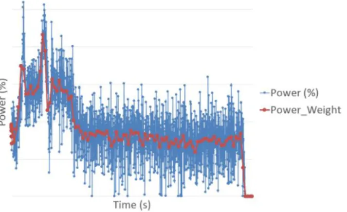
As shown the blue curve inFig. 4, the global power input for the MW oven could be nonlinear and look like a series of ON/OFF with a certain frequency to follow a global mean heating cycle curve. The EM simulations are done with the maximum equivalent power of the magnetrons. As a consequence, the power 𝑃(𝑓) used to calculate Q is weighted by a curve function of time 𝑤𝑔(𝑡), 0 ≤ 𝑤𝑔 ≤ 1 (the red curve in Fig. 4). This function is deduced by averaging the real input power ratio
curve on each time step of the simulation.
The problem is then solved with linear FE method in PAM-COMPOSITE® solver.
Fig. 4. Magnetrons power ratio curve vs time (blue curve) and equivalent mean power ratio curve used in PAM-COMPOSITES® to weighting the thermal source (calculate at power max) along the process time (red curve)
4. Parametric solution for inline simulation
One run of the offline solver involved a computing time reasonable for few analyses but is not designed for neither magnetron power curve optimization which could demand hundreds of simulations, nor for real-time control in operation.
To reach that goal, a first model reduction technic has been applied on the heat equation, considering exothermic (resin curing) and electromagnetic heat sources, under the constraint of tuneable power delivered by the magnetron in the oven cavity at each time step. With the offline solver, many snapshots of the temperature field T as the exothermic source term S (induced by the resin curing) are collected, and the SVD performed. Respective reduced basis could then be extracted, consisting of eigenvectors associated with the higher eigenvalues. These vectors are respectively named Φ𝑙 and
Ψ𝑚, with 𝑙 = 1, … , ℒ and 𝑚 = 1, … , ℳ with both ℒ and ℳ much smaller than the number of nodes
𝑁 used in the discretization space. Thanks to these bases, the variables T and S could be approximated at any time 𝑡𝑛 according to (Eq. 7) and (Eq. 8):
𝑇𝑛 ≈ ∑ 𝛽 𝑙𝑛Φ𝑙 ℒ 𝑙=1 ⟺ 𝑇𝑛 ≈ Φ𝛽𝑛 (Eq. 7) 𝑆𝑛 ≈ ∑ 𝛾 𝑚𝑛Ψ𝑚 ℳ 𝑙=1 ⟺ 𝑆𝑛 ≈ ΨΥ𝑛 (Eq. 8)
7
Where Φ and Ψ are respectively composed by the vectors Φ𝑙 and Ψ𝑚.
To calculate the parametric reduced model, an implicit discretization of the heat equation is considered for its stability performances. After discretizing Eq. 4 and projecting onto the reduced basis, the reduced discrete linear system is obtained:
Φ𝑇(𝑀 − Δ𝑡𝐾)Φ𝛽𝑛+1 = Δ𝑡Ρ𝑛+1Φ𝑇Θ + Δ𝑡Φ𝑇ΨΥ𝑛+ Φ𝑇MΦ𝛽𝑛 (Eq. 9)
Where M is the traditional mass matrix; K is the stiffness matrix; the heat source Q is decomposed in 𝑃𝑛Θ where 𝑃𝑛 is the magnetrons’ power at 𝑡
𝑛 and Θ is the electromagnetic heat source field when
P=1.
Because of the linearity of Eq. 9, this last can be solved for a unit power (with curing and previous temperature vanishing), then for a unit curing contribution (with the other two contributions vanishing) and then for a unit contribution of the previous temperature while vanishing the other two contributions. Then, as soon as the temperature is updated, the reduced curing contribution can be updated, and with the applied power, the new temperature computed under the stringent real-time constraint. For more detail the interested reader can refer to [10].
5. Test case
As shown in Fig. 5, the test case is a composite plate of dimensions 3 mm x 200 mm x 200 mm, cured in a mold especially designed for the process (transparent to the EM MW, except on a thin coat layer at the interface between the mold and the composite). The composite is made of carbon fibres with a volume content of 0.6 and filled with RTM6 resin. RTM6 kinetic properties can be found in [8]. The initial temperature of the mold and the composite parts is supposed to be room temperature. A convection boundary condition mold/air is applied on the external surface of the mold. For this test case, a perfect interface has been used between the composite and the mold, without thermal contact resistance at the interface.
Fig. 5. Geometry of the test case
Convection boundary conditions (BC) are applied all around the mold. Two kind of convection BC are considered: the one between the mold and the metallic table, and the one between the mold and the air. They are respectively set to 100 W/(m².K) and 10 W/(m².K). Besides, three different configurations are simulated and compared to experimental results:
8
1- The mold is supposed to be set on a plain table. Thus, convection type mold/table is applied on the full lower surface, while convection mold/air type is applied on the other surfaces (Fig. 5.a).
2- As shown in Fig. 1, the table surface is not plain, but a grid, and more realistic convection BC is applied on the lower surface, according the position of the plate on the table (Fig. 5.b). 3- The convection BC are the same than 2, but the total amplitude of the input power is reduced
by 20%, considering some electromagnetic loss in the oven due to leakages. In further works, these losses have been more realistically modelled in the STEP 1 model, but this is not presented in the present paper. However, we can say that these ones increased with the free volume in the cavity, and thus decreased for the industrial demonstrators which are more voluminous parts.
(a) (b)
Fig. 6. Different convection boundary conditions tested: (a) the mold is put on a plain table; (b) the mold is put on a more realistic table as the one used in the experiment.
6. Results
Around 25 minutes, a snapshot of the temperature and the degree of cure fields has been made and presented in Fig. 7. First remark is that the temperature field, as the curing one, is quite heterogenous, showing the complexity of the process and the need to use the simulation platform for its design. Especially, the role of the absorbing layer between the mold and the composite could play an important role to decrease this inhomogeneity, and its thickness should be optimized. In the same way, the power history of the magnetron should be optimized thanks to the inline solver to reduce again the inhomogeneity.
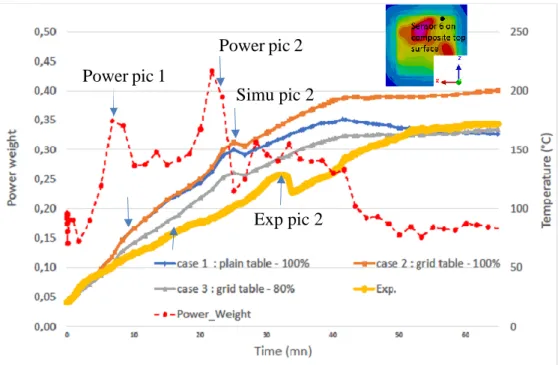
Experimental temperature measured with an optical sensor is compared to the temperature history assessed with the three simulated configurations. As depicted in Fig 8, after 1h of MW heating the control temperature fits quite well with the 1st and 3rd cases considered. However, while case 1 has a good trend, adjustment to better fit the reality on this modelling performed in case 2 leads to an over-estimation of the temperature of 40°C. Last while considering in case 3 the leakages due to a small volume of matter to heat in the oven, we recover quite well the measured temperature. Improving the modelling of the EM losses and the values of the boundary conditions should improve in turn this first evaluation.
When considering the temperature during the ramp-up before 50 min, the simulated temperatures seem increasing faster than the experimental one. Some additional simulations are on-going to check some parameter sensitivity, as the thermal material properties for instance, and see if one of these could explain this trend. Another observation in Fig.8 concerns the 2 high pics of the power curve
9
(the one used for the present simulations): they induce local temperature increases in both experimental and the simulation curves, but with a delay for the experimental one. The high electromagnetic field heterogeneity and some incertitude on the right sensor position may explain this observation. Indeed, the electromagnetic spots induces also high heating spots, and the diffusion time of the heat from these spots to the sensor could induce some delay on the curve pics.
Fig. 7. Snapshot of temperature (left) and degree of cure (right) fields for the case 1. Only the lower part of the mold and the composite one are presented in these snapshot, the upper mold is masked.
Fig. 8. Comparison experimental evolution of the temperature at a sensor and the simulated ones for the 3 different cases. Evolution of the power weight curve during the same time.
7. Conclusions and perspectives
In this paper we have shown the feasibility to simulate the heating and the curing of composite part inside an industrial micro-wave oven by chaining an EM simulation (step 1) with a heating-curing
Power pic 2 Power pic 1
Simu pic 2
10
simulation (step 3). first experimental and simulation comparisons have shown the importance to have both a good evaluation of the boundary conditions, as well as a consideration of the electromagnetic losses in the oven.
These chained simulations took several hours in total with an initial electromagnetic model containing around 8 million elements, which is acceptable for few analyses during the process design. However, it’s not reasonable for optimisation purpose which needs plenty of simulations. A methodology to build a parametric solution has thus been proposed, so that the solution at each time step could be predicted quasi-instantly, making possible the optimisation of the magnetron power at each time step. In the next step this parametric solution would be coupled with a control loop model to complete the whole simulation module, and thus address real-time control in operation.
Acknowledgment
This work has been done in the framework of SIMUTOOL project (H2020).
References
[1] G. Hug, “Behavior analysis of carbon-epoxy laminates under high-speed loading: manufacture of the same materials by means of microwave curing for comparison” Ph.D. thesis, Arts et Métiers ParisTech, 2005. [2] L. Feher, K. Drechsler and J. Pfilsinger, “Composite manufacturing by using a novel modular 2.45 GHz
microwave processing system”, in 36th International SAMPE Technical Conference, San Diego, CA, USA. (2004)
[3] R. Youssof, M.K. Aroua, A. Nesbitt and R.J. Day, “Curing of polymeric composites using microwave resin transfer moulding (RTM)”, in Journal of Engineering Science and Technology, 2(2), 51-163.
[4] M. Kwak, P. Robinson, A. Bismarck and R. Wise, “Curing of Composite Materials Using the Recently Developed Hephaistos Microwave”, in 18th International Conference on Composite Materials, 21-26 (2011). [5] ESI GROUP, “CEM One Solution”, http://www.esi-group.com/
[6] ESI GROUP, “PAM-COMPOSITES”, http://www.esi-group.com/
[7] F. Berthet, S. Nakouzi , F. Schmidt et Yannick le Maoult, « Cartes de température maximum lors de la simulation de la réticulation de la résine RTM 6 dans une plaque composite », Comptes Rendus des JNC 17, Poitiers, France, 2011.
[8] H. Tertrais, R. Ibanez, A. Barasinski and F. Chinesta, “Microwave processing of laminated part: Application to glass fiber reinforced polymer (GFRP)”, IMPI’s 51st ANNUAL MICROWAVE POWER SYMPOSIUM, Miami, Florida, USA, June 2017.
[9] H. Tertrais, R. Ibanez, A. Barasinski, C. Ghnatiosand F. Chinesta, “Simulation of Microwave Heating of Composite Part in an Oven Cavity”, IMPI’s 51st ANNUAL MICROWAVE POWER SYMPOSIUM, Miami, Florida, USA, June 2017.
[10] H. Tertrais « Développement d’un outil de simulation pour le chauffage de matériaux composites par micro-ondes », Ph.D. thesis, Ecole Centrale de Nantes, 2018.