Science Arts & Métiers (SAM)
is an open access repository that collects the work of Arts et Métiers Institute of
Technology researchers and makes it freely available over the web where possible.
This is an author-deposited version published in: https://sam.ensam.eu Handle ID: .http://hdl.handle.net/10985/16787
To cite this version :
Huijun SONG, Benoit EYNARD, Pascal LAFON, Lionel ROUCOULES - Towards Integration of CAx Systems and a Mul ti ple-View Prod uct Mod el ler in Mechanical Design - Acta Polytechnica - Vol. 45, n°3, p.26-31 - 2005
1 In tro duc tion
The de mand for a high qual ity, low cost prod uct with a short de vel op ment time for the dy namic global mar ket has forced re search ers and in dus tries to fo cus on var i ous ef fec tive prod uct de vel op ment strat e gies. Con cur rent en gi neer ing is an ef fec tive ap proach to re duce prod uct de vel op ment lead time and im prove the over all lifecycle qual ity by in cor po rat -ing down stream prod uct de vel op ment con sid er ations into the early de sign stage. The prod uct de vel op ment pro cess deals with var i ous kinds of data is sued from value en gi neer -ing, struc tural break down, DFX as sess ments, etc. In te gra tion of prod uct data in each de sign phase (con cep tual de sign, em -bodi ment de sign and de tail de sign, Pahl and Beitz [1]) will pro vide more com plete in for ma tion-based de ci sion mak ing. Prod uct mod el ling has been rec og nized as an ef fec tive tech -nique for fa cil i tat ing the rep re sen ta tion and man age ment of prod uct data.
Dur ing the 1990s many re search works deal ing with prod -uct mod el ling were pub lished by Krause et al. [2], Laakko and Mäntylä [3], Anderl and Mendgen [4]. The main ap proach of these works was to de scribe the prod uct based on geo met ric and form fea tures. In re cent years, the re search fo cus of prod -uct mod el ling has grad u ally shifted to the ear lier de sign phase. Es sen tially, the ear lier de sign phase is func tion-driven or func tion-ori ented, be cause the main de sign fo cus at this stage is to find a de sign so lu tion that is able to achieve the required func tions. Form fea ture mod el ling ap proaches and sys tems, deal ing mainly with ge om e try, can not take func tional in for ma tion into ac count at all, be cause this in for ma tion is a more ab stract con cept than geo met ric and top o log i cal in for -ma tion. In such a sit u a tion, prod uct mod el ling ori ented to func tional de sign has been widely stud ied. The main idea of these mod el ling ap proaches is to de scribe the re la tion ships be tween func tions, be hav iours and struc tures dur ing the de -sign pro cess, Umeda et al. [5], Deng et al. [6], Zhang et al. [7].
The rep re sen ta tion of the data that has to be man aged dur ing the prod uct de vel op ment pro cess de pends on the design phase. It is hardly fea si ble to find an all-round per fect prod uct model which is able to han dle all the prod uct data aspects above. In the pre sented re search work, two mod els are used to deal with prod uct data from the con cep tual phase
to the de tail de sign phase. A Func tion-Be hav iour-Struc ture (FBS) model is em ployed for the con cep tual and em bodi -ment de sign phase, and a mul ti ple-view model is used for the em bodi ment and de tail de sign phase. As we know, com -mer cial CAD sys tems pro vide pow er ful ca pa bil ity in CAD mod el ling and anal y sis. Cur rently, the re search aim is to obtain the link ing which will in te grate these three mod els.
This re search pro poses an in te gra tion frame work about dif fer ent as pects of prod uct data. On the con cep tual level, the dif fer ent kinds of prod uct data and their log i cal re la tions are de scribed through func tional mod el ling and mul ti ple --view mod el ling and CAD mod el ling. On the im ple men ta tion level, the in te gra tion of the func tional mod el ler, the mul ti ple view prod uct mod el ler and CATIA com pose the en vi ron ment for im ple ment ing the mod el ling logics pro vided on the con -cep tual level. The data ex change be tween CATIA and an already-existing op ti mi sa tion mod ule is also con sid ered to aid de sign ers for a quick as sess ment of a sub-as sem bly tak ing into ac count a set of eval u a tion cri te ria.
This pa per is or gan ised as fol lows: (1) an in te gra tion frame work for mul ti ple as pects of prod uct data is pro posed, (2) as an ap pli ca tion of this frame work, the FBS model and mul ti ple-view model are briefly de scribed and the link ing between them is emphasised, (3) the in te gra tion of the im -plementing mod el lers is de scribed, es pe cially de tails of the link ing be tween the mul ti ple-view mod el ler and CATIA is discussed, (5) the con clu sions and fu ture work are pre sented.
2 The pro posed in te gra tion
frame work
The prod uct de vel op ment pro cess deals with dif fer ent kinds of data in each de sign phase. Dur ing the phase of task clar i fi ca tion, the de sign spec i fi ca tions orig i nat ing from cus -tomer re quire ments are the de scrip tion of a prod uct to be designed; dur ing the con cep tual de sign, the means (prin ci ple so lu tions or com po nents) are gen er ated to meet the func -tional re quire ments; then the con fig u ra tions of each of the com po nents and the con nec tions be tween the com po nents are set dur ing the em bodi ment de sign; af ter that, fi nal de -cisions on di men sions, ar range ment, shapes of in di vid ual
To wards In te gra tion of CAx Sys tems and
a Mul ti ple-View Prod uct Mod el ler in
Me chan i cal Design
H. Song, B. Eynard, P. Lafon, L. Roucoules
This pa per deals with the de vel op ment of an in te gra tion frame work and its im ple men ta tion for the connexion of CAx sys tems and mul ti ple-view prod uct mod el ling. The in te gra tion frame work is pre sented re gard ing its con cep tual level and the im ple men ta tion level is de scribed cur rently with the connexion of a func tional mod el ler, a mul ti ple-view prod uct mod el ler, an op ti mi sa tion mod ule and a CAD sys tem. The in te gra tion be tween the mul ti ple-view prod uct mod el ler and CATIA V5 based on the STEP stan dard is de scribed in de tail. Fi nally, the pre sented works are discussed and future research developments are suggested.
components and ma te ri als are made, giv ing due con sid er -ation to the man u fac tur ing func tion in the de tail de sign. As men tioned in sec tion 1, the mod el ling of prod uct data de -pends on the de sign phase. It is ob vi ously dif fi cult to han dle all the as pects of prod uct data given above in an all-round model. The key to prod uct mod el ling is prod uct model par ti -tion and in te gra -tion. Fig. 1 shows an over view of the pro posed in te gra tion frame work. The pur pose of this frame work is to pro vide meth ods and tools to en able prod uct data in te gra tion in a con cur rent en gi neer ing approach.
Sev eral map ping meth ods have been pro posed to im ple -ment sys tem in te gra tion within the prod uct mod el ling area. In Nowak et al. [8], a meta-mod el ling based method has been pro posed for the in te gra tion of prod uct mod els. A for mal mod el ling no ta tion is re quired for the def i ni tion of mappings on the con cep tual level. This no ta tion pro vides a method to de scribe the cor re spon dences be tween the mod els. Af ter the map ping has been de fined, it is pos si ble to trans late data to the im ple men ta tion level.
Ac cord ing to the iden ti fied prod uct data in dif fer ent de -sign phases, the fol low ing mod el ling tech niques are adopted on the con cep tual level:
1) Cus tomer re quire ment mod el ling: the cus tomer re quire -ments are ana lysed and trans lated into a state ment which de fines the func tion that the prod uct should pro vide (re -ferred to as a func tional re quire ment) and the phys i cal requirements that the prod uct must satisfy.
2) Func tional mod el ling: to de scribe a de sign and its re -quire ments from its func tional as pects so as to al low reasoning about its func tion al ity and gen er at ing schemes. 3) Mul ti pleview mod el ling: to em bed en gi neer ing knowl
-edge (ge om e try, pro cess plan ning, man u fac tur ing, assemb ly, etc.) into the de scrip tion of the form fea tures. 4) CAD mod el ling: to de scribe the geo met ric and top o log i
-cal in for ma tion and to en able an anal y sis.
Ac cord ing to the prod uct mod el ling tech niques pro vided on the con cep tual level, the cor re spond ing im ple ment ing systems have al ready been de vel oped by re search in sti tutes
or com mer cial com pa nies. These im ple ment ing tools and their re la tion ships com pose the im ple men ta tion level in the frame work. There are a num ber of tech niques for cus tomer re quire ment mod el ling. The most well-known of these techniques is Qual ity Func tion De ploy ment (QFD). The func -tional mod el ler and the mul ti ple-view mod el ler have already been de vel oped re spec tively by Song [9], Roucoules and Tich -kiewitch [10]. The com mer cial CATIA V5, from Dassault Systemes (www.3ds.com), is used here for clas si cal CAD mod -el ling. To aid de sign ers to make a quick as sess went of a sub-as sem bly tak ing into ac count a set of eval u a tion cri te ria, the al readyde vel oped op ti mi sa tion mod ule is also con sid -ered to be in te grated into the pro posed frame work.
As this re search work fo cuses on me chan i cal de sign, cus -tomer re quire ment mod el ling and its mod el ler sys tem is not con sid ered cur rently. On the con cep tual level, the in te gra tion of func tional mod el ling and mul ti ple-view mod el ling will be emphasised; on the im ple men ta tion level, the data ex change be tween the mul ti ple-view mod el ler and CATIA V5 will be focused on.
3 Product modelling
In this sec tion, we will first briefly de scribe the two mod els our work is based on. Then the in te gra tion of these two mod -els will be emphasised.
3.1 Func tional mod el ling
The idea of func tional mod el ling in con cep tual and em -bodi ment de sign is to rea son at the func tional level in or der to gen er ate so lu tions to spec i fied de sign prob lems. The prod uct re quire ments are pro gres sively mapped onto prod uct struc -tures via functional modelling.
To sup port func tional mod el ling, it is now gen er ally ac -cepted that de sign in for ma tion should in clude not only the phys i cal struc ture of a de sign, but also its re quired func tions and im ple ment ing be hav iour [6]. For ex am ple, the func tion of a steam valve in a boiler is to pre vent an ex plo sion; its be -hav iour is that it opens when a cer tain pres sure dif fer ence is
CAD Modelling Task Clarification Conceptual Design Embodiment Design Detail Design Customer requirements modelling C o n ce p tu a l le ve l Im p le m en ta ti o n le v e l Customer requirements modeller Functional modeller Multiple View Product Modeller CATIA Optimisation Module Mutiple View Modelling
Product Development Process
Functional modelling
de tected; its struc ture is the phys i cal lay out and the con nec -tion be tween the var i ous phys i cal com po nents [11]. Fig. 2 shows a func tional rep re sen ta tion of the struc ture. This rep re -sen ta tion sug gests that each given struc ture be de scribed by
the be hav iours it can pro vide and the func tions pro vided by the be hav iours, and in or der to provide each of these, the functions that the structure requires.
The search for a so lu tion to a given prob lem, de fined in terms of a given set of de sired func tions, would start with a search among the known be hav iours for those that can pro -vide the de sired func tions, then among the known struc tures for those that can pro vide the in tended be hav iours. These cho sen struc tures, in turn, re quire some other func tions in order that they can pro vide the de sired func tions. Now, new be hav iours and struc tures will be searched for, so as to pro vide these re quired func tions, which in turn give rise to new func -tional re quire ments. This pro cess will con tinue un til all the required func tions are pro vided by some struc tures. Each resulting com bi na tion of struc tures evolved by the above pro -cess thereby be comes a so lu tion to the design problem posed at the beginning.
As the de sign level de creases (from ab stract to con crete), the dif fer ence be tween the mean ing of func tion and be hav -iour be comes more and more vague. In such a sit u a tion, a func tion may be mapped onto a struc ture with out the be hav -iour as the tran si tion. For ex am ple, the in tended func tion “transmitting torque” can be mapped onto a struc ture “shaft” When a func tion may not be mapped onto a be hav iour or a struc ture, it may be bro ken down into sub-func tions. Thus, the be hav iour or struc ture in the above rep re sen ta tion may be a vir tual node. A de tailed dis cus sion about the mappings in func tional mod el ling is presented by Song and Lin [12].
3.2 Mul ti ple-view mod el ling
For em bodi ment and de tail de sign, a mul ti ple-view model is used. The prod uct has sev eral break downs ac cord ing to different points of view, i.e., the prod uct has mul ti ple-view break downs. The mul ti ple-view break down was in tro duced by Chapa and de tailed in [10] to gather all the data that de scribe
a prod uct with a spe cific vi sion of it. Fig. 3 shows an ex am ple of the mul ti pleview ap proach with: tech nol ogy, man u fac tur -ing, as sem bly and fi nite el e ment anal y sis views. Roucoules et al. [13] de scribe the integration of the process planning view.
This rep re sen ta tion al lows mul ti ple-views break down of the prod uct and en sures the link with the ge om e try. These fea ture-based break downs com plete the prod uct def i ni tion, add ing new data and new con straints from spe cific points of view such as tool ing, fi nite el e ment anal y sis, etc. The mul ti -ple-view model is fully de scribed in [14].
3.3 In te gra tion of the func tional model and the
mul ti ple-view model (con cep tual level)
To in te grate the func tional model and the mul ti ple-view model, it is nec es sary to es tab lish the link ing be tween these two mod els. A fea si ble way is to find the re la tion ship be tween the re sults of func tional mod el ling and the ini tial in for ma -tion of mul ti ple-view mod el ling. The scheme gen er ated from func tional mod el ling is de scribed by the in for ma tion on func -tion, be hav iour and struc ture in terms of the rep re sen ta tion model as shown in Fig. 2. The mul ti ple-view break downs start from some struc tures in mul ti ple-view mod el ling. Thus, both mod els hold the in for ma tion on the struc tural de scrip tion. It is ob vi ous that the struc tural de scrip tions in these two mod els are in fact dif fer ent. The ob jec tive of func tional modelling is to gen er ate an out line scheme, so the struc tures here are the com po nents on the up per de sign level. In the mul ti ple-view model, the struc ture de scrip tions are rel a tively de tailed. It is nev er the less sug gested that the ter mi nal point of func tional
F
F S B
P R
P Indicates to the functions or behaviors provided R R F: function B: behavior S: structure F P
Indicates from the functions provided Fig. 2: Func tional rep re sen ta tion of a struc ture
Multiple -view modelling Technology
Assembly Finite element analysis
Manufacturing
view 1 view 2
view 3 view 4
Fig. 3: Mul ti ple-view model
1 1 1 2 2 3 3 4 4 3 4 2 function structure behavior 1 Link1 Link2 Link3 Relation 2 3 4 e ch n o lo is t vi e w
Functional modelling Multiple-view modelling
T
echnologist view
mod el ling over laps with the start ing point of mul ti ple-view modelling. Fig. 4 shows the integration frame work between these two models.
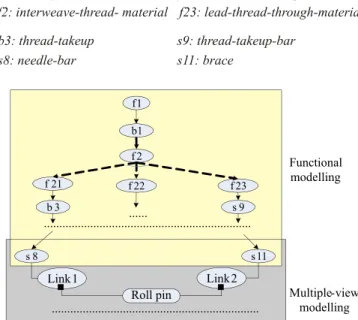
From the in te gra tion frame work, the struc ture which is the ter mi nal node in func tional mod el ling can be shifted to the tech nol ogy view in mul ti pleview mod el ling. Thus, func -tional re la tion ships that ex ist be tween struc tures, such as drive, sup port, hold, lo cate, and cou ple etc., can be ana lysed fur ther. Fig ure 5 shows the in te gra tion of the two mod els with an ex am ple of a component in a sewing machine.
4 Integration on the implementation
level
In this sec tion, in te gra tion be tween the im ple ment ing sys -tems is dis cussed. There are four dif fer ent ap proaches to the data ex change prob lem: man ual rein put of data, di rect trans la tion, neu tral for mat trans la tion, and a shared prod uct da ta -base [15]. Each ap proach has its own pros and cons. Di rect trans la tion is the sim ple and ac cu rate so lu tion, but the num -ber of the trans la tors in creases ex po nen tially with the num -ber of sys tems in volved. The last two so lu tions are reasonable, flexible, and adaptable.
4.1 Link ing be tween a func tional mod el ler and a
mul ti ple-view mod el ler
The func tional mod el ler is a knowl edge-based ex pert system, which sup ports func tional rea son ing based on do -main -spe cific knowl edge. It was de vel oped us ing a CLIPS expert sys tem shell (C Lan guage In te grated Pro duc tion System) [16]. As ex plained in sec tion 3.3, the struc tural in for -ma tion plays the internuncial role be tween the func tional mod el ling and mul ti ple-view mod el ling. Af ter the func tional mod el ling, the schemes which contextualised the func tional prod uct data are out put in a neu tral plain text file. Then the mul ti ple-view mod el ler can read the re lated struc tures from
the neu tral file. Thus, ac cord ing to the struc tures, the dif fer -ent aspects of the product data can easily be retrieved.
4.2 Link ing be tween CATIA V5 and op ti mi sa tion
mod ule
In te gra tion of the op ti mi sa tion mod ule into the pro posed frame work al lows de sign ers to quickly as sess a sub-as sem bly, tak ing into ac count a set of eval u a tion cri te ria and to eval u ate the in flu ence of the data on the de sign so lu tions by mod i fy ing one or more item [17]. The mech a nism of data ex change between CATIA V5 and the de vel oped op ti mi sa tion mod ule is shown in Fig. 6. In CATIA V5, the op ti mi sa tion prob lem is ab stracted from the parameterised geo met ric model. The parameters and con straints which de fine the op ti mi sa tion prob lem are out put into a neu tral file by call ing CAA-API (Com po nent Ap pli ca tion Ar chi tec ture Ap pli ca tion Pro gram -ming In ter face) of CATIA V5. Then, the op ti mi sa tion mod ule reads the data from the neu tral file and per forms the op ti mi -sa tion op er a tion. The op ti mal val ues of the vari ables are output into a neu tral file. Fi nally, CATIA V5 gets back the results from the neutral file by calling CAA-API and updates the geometric model.
4.3 Link ing be tween the mul ti ple-view mod el ler
and CATIA V5
In the CAD/CAM con text, there ex ist sev eral stan dards for data ex change, such as IGES, SET, VDA-FS, EDIF, etc. [18]. The most pop u lar ex change stan dard in use is IGES. It was de signed as a neu tral for mat for the IGES ex change of CAD data, and has been used as the stan dard for geo met ric data by most CAD/CAM sys tems. Al though IGES is best sup ported as an in ter change for mat for geo met ric data, it can not ful fill the com plete ness re quire ment in rep re sent ing prod uct data. STEP was first pro posed in 1984 [19] to rep re sent com plete in for ma tion of a prod uct through out its life cy cle. Then the choice was made that the data ex change be tween the mul ti -ple-view mod el ler and CATIA V5 would be based on STEP. An other ap proach was de vel oped in Eynard et al. [20], aim ing at a di rect connexion of the mul ti ple-view mod el ler and an opensource CAD system based on on OpenCASCADE libraries.
The rel e vant out put data from the mul ti ple-view mod el ler is con verted into STEP file for mat by a trans la tor, and then the STEP file can be opened by CATIA V5 di rectly. The key to this data ex change is the de vel op ment of a Trans la tor. This mod ule has al ready been de vel oped us ing MS Vi sual C++ 6.0. Con sid er ing the re us abil ity and ex ten si bil ity of the mod ule, the map ping about an en tity from the out put file of the mul ti ple-view mod el ler onto the STEP neu tral file is f1 f 2 f 22 f 21 f 23 b 3 s 8 s 9 b1 s 11 ... Link 2 Link 1 Roll pin ... Functional modelling Multiple-view modelling ... f1: join-material b1: sewing f2: interweave-thread- material f21: tense-stitch f22: catch-thread-loop f23: lead-thread-through-material s11: brace b3: thread-takeup s9: thread-takeup-bar s8: needle-bar
Fig. 5: A case of in te gra tion of a func tional model and a mul ti -ple-view model
CATIA V5
Parameterized geometrical model CATIA V5
Preformulated optimisation problem Optimisation algorithms Optimal values of parameters Parameters and constraints Update CAA-API CAA-API
Fig. 6: Data ex change be tween CATIA V5 and the op ti mi sa tion module
encapsulated into a class which pro vides a com pact in ter face for ac cess ing. When an en tity of the STEP file is needed, the only thing to be done is to ex tract the re quired pa ram e -ters and call the cor re spond ing class mem ber func tion. For example, the cy lin dri cal surface defined by the multiple-view modeller is shown as follows:
{ axe SLine : pl_axe_doigt_cyl4 dir Vec tor : pl_dir_axe_doigt_cyl4
z Float : [0.000000..0.000000] y Float : [1.000000..1.000000] x Float : [0.000000..0.000000] di am e ter Float : [12.0 .. 12.0] po si tion Point : pl_pos_doigt_cyl4
z Float : [0.000000..0.000000] y Float : [-20.000000..-20.000000] x Float : [0.000000..0.000000] length Float : [30.0 .. 30.0]}
The pa ram e ters re quired by the trans la tor are the cen ter points of each sec tion cir cle and the ra dius. The two cen ter points are cen ter 1 (0, -20, 0) and cen ter 2 (0, 10, 0); the radius is 12. Then, a cy lin dri cal sur face ob ject (css) can be built with the pa ram e ters and we call its mem ber func tion (GetSTEPCode) to get the STEP code.
CCylindrical_sur face_seg ment css(center1,center2, ra dius), Css.GetSTEPCode.
The ob tained STEP file is shown as fol lows (in part):
#51=CAR TE SIAN_POINT('Axis2P3D Lo ca tion',(- 5.,0.,0.));
#52=DI REC TION('Axis2P3D Di rec tion',(0.,1.,0.)); #53=DI REC TION('Axis2P3D XDirection',(-1., 0.,0.)); #54=AXIS2_PLACE MENT_3D('Cyl in der Axis2P3D',
#51,#52,#53); #55=CY LIN DRI CAL_SUR FACE('gen er ated cyl in der',
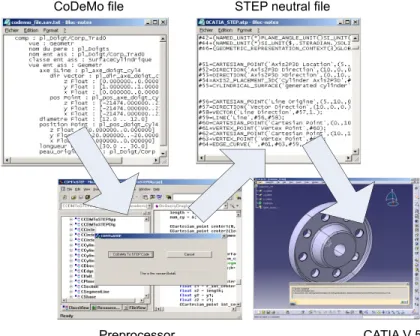
#54,6.); ... Fig. 7 shows the in ter faces of the pro cess of data ex change.
5 Conclusion
The re search work pre sented in this pa per deals with prod uct data in te gra tion in de sign. Lasts of this prob lem have been stud ied in the lit er a ture and some con cepts have been well spec i fied. The cur rent re search work fo cuses on de vel op -ing a new in te gra tion ap proach and associated systems.
An in te gra tion frame work of a CAx sys tem and a mul ti -ple-view mod el ler is pro posed. On the con cep tual level, an FBS model and the mul ti ple-view model are used to rep re sent the prod uct data dur ing the de sign pro cess. The link ing between these two mod els is es tab lished to en able the in te gra -tion of prod uct data in each de sign phase (con cep tual de sign, em bodi ment de sign and de tail de sign). On the im ple men ta -tion level, the data ex change be tween the cor re spond ing mod el lers is car ried out by neu tral file trans la tion. There fore, the de signer can eas ily ac cess the prod uct data from dif fer ent views and contextualise it through out the prod uct de vel op -ment pro cess. This re search work pro vides de sign ers with a com pre hen sive prod uct model and their modelers so as to help them to make information-based design decisions.
Ref er ences
[1] Pahl, G., Beitz W.: En gi neer ing De sign : A Sys tem atic Ap
-proach. Springer. Lon don, 1996.
[2] Krause, F. L. et al: “Prod uct Mod el ling.” An nals of the
CIRP, Vol. 42(1993), No. 2, p. 695–706.
[3] Laakko, T., Mäntylä, M.: “Fea ture Mod el ling by In -cremental Fea ture Rec og ni tion.” Com puter-Aided De sign, Vol. 25 (1993), No. 8, p. 479–492.
[4] Anderl, R., Mendgen, R.: “Mod el ling with Con straints: The o ret i cal Foun da tion and Ap pli ca tions.” Com puter
--Aided De sign, Vol. 28 (1996), No. 3, p. 155–166.
[5] Umeda, Y., Ishii, M., Yoshioka, M., Tomiyama, T.: “ Supporting Con cep tual De sign Based on the Func tion Be hav iorState Mod eler.” Ar ti fi cial In tel li gence for En gi -Acta Polytechnica Vol. 45 No. 3/2005
CoDeMo file STEP neutral file
Preprocessor CATIA V 5 Fig. 7: Ex am ple of data ex change be tween a mul ti ple-views mod el ler and CATIA V5
neer ing De sign, Anal y sis and Man u fac tur ing, Vol. 10 (1996),
p. 275–288.
[6] Deng, Y.-M., Tor, S. B., Britton, G. A.: “A Dual-Stage Func tional Mod el ling Frame work with Mul ti level De -sign Knowl edge for Con cep tual Me chan i cal De -sign.”
Jour nal of En gi neer ing De sign, Vol. 11(2000), No. 4, p.
347–375.
[7] Zhang, Tor, S. B., Britton, G. A., Deng Y.-M.: “EFDEX: A Knowl edgeBased Ex pert Sys tem for Func tional De -sign of En gi neer ing Sys tems.” En gi neer ing with Com put
-ers, Vol. 17 (2001), No. 4, p. 339–353.
[8] Nowak, P., Roucoules, L., Eynard, B.: “Prod uct Meta --Mod el ling: An Ap proach for Link ing Prod uct Mod els.” In: Proc. of the IEEE World Con gress on System, Man and Cy ber net ics. Tu ni sia: Hammamet, Oc to ber 6th–9th, 2002.
[9] Song, H. J.: “Re search on Meth od ol ogy and Key Tech -niques of Scheme Gen er a tion in Con cep tual De sign of Me chan i cal Prod ucts.” PhD The sis (in Chi nese). Xi’an Jiaotong Uni ver sity, China, 2003.
[10] Roucoules, L., Tichkiewitch, S.: “CoDE: a Co-op er a -tive De sign En vi ron ment. A New Gen er a tion of CAD Systems.” Con cur rent En gi neer ing Re search and Ap pli ca tion, Vol. 8 (2000), No. 4, p. 263–280.
[11] Kuipers, B.: “Common sense Rea son ing About Cau sal ity: De riv ing Be hav iour From Struc ture.” Ar ti fi cial In tel li
-gence, Vol. 24(1984), No. 1–3, p. 169–203.
[12] Song, H. J., Lin, Z. H.: “Hi er ar chi cal Func tion Solv ing Frame work with Hy brid Mappings in Con cep tual De -sign of Me chan i cal Prod ucts.” Chi nese Jour nal of Me chan i
-cal En gi neer ing, Vol. 38 (2003), 5, p. 82–87.
[13] Roucoules, L., Salomon, O., Paris, H.: “Pro cess Plan ning as an In te gra tion of Knowl edge in the De tailed De sign Phase.” In ter na tional Jour nal of Com puter In te grated Man u
-fac tur ing, Vol. 16 (2003), No. 1, p. 25–37.
[14] Tichkiewitch, S.: “Spec i fi ca tion on In te grated De sign Meth od ol ogy Us ing a Multi-view Prod uct Model.” In: roc. of ASME En gi neer ing Sys tem De sign and Anal y sis Con fer ence Montpellier, France, July, 1996.
[15] Fowler, J.: STEP for Data Man age ment, Ex change and Shar ing. Tech nol ogy Ap prais als, 1995.
[16] Giarratano, J., Riley, G.: Ex pert Sys tems: Prin ci ples and
Pro gram ming. 3rd ed. Boston, PWS, 1998.
[17] Eynard, B., Lafon, P.: To wards a Me chan i cal Sys tems Mod el ling and Op ti mal Em bodi ment Method. In: Proc. of 13th In ter na tional Con fer ence on En gi neer ing De sign Glas gow, Scot land, UK, Au gust 21st–23rd, 2001. [18] Bloor, M. S., Owen, J.: “CAD/CAM Prod uctData Ex
-changement: the Next Step.” Com puter-aided De sign, Vol. (1991), p. 237–243.
[19] ISO10303-1. STEP: In dus trial Au to ma tion Sys tems and In -te gra tion Prod uct Data Rep re sen ta tion and Ex change, Part 1.
Over view and fun da men tal prin ci ples, 1994.
[20] Eynard, B., Roucoules, L., Yan, X.T.: “Knowl edge In te -gra tion Ap proach for Prod uct Mod el ling Us ing an Opensource CAD Sys tem.” In: Proc. of 5th Knowl edge In ten sive CAD IFIP5.2 Work shop. St. Julian, Malta, July 23rd–25th, 2002. Dr. Huijun Song phone: +33 325 715 671 fax: +33 325 715 675 e-mail: song.huijun@utt.fr Dr. Benoît Eynard e-mail: benoit.eynard@utt.fr Dr. Pascal Lafon e-mail: pascal.lafon@utt.fr Dr. Lionel Roucoules e-mail: lionel.roucoules@utt.fr Troyes Uni ver sity of Tech nol ogy
Lab o ra tory of Me chan i cal Sys tems and Con cur rent En gi -neer ing–FRE 2719 CNRS
12 rue Ma rie Cu rie