[email protected]
Testing steel lattice towers with a hybrid (numerical/ experimental) method
A. Loignon, S.Langlois, C.-P. Lamarche, F. Légeron
Université de Sherbrooke
Canada
[email protected]
SUMMARY
The analysis of transmission line steel lattice towers is usually performed with linear numerical methods. However, the actual behaviour of bolted lattice towers is complex and may be highly affected by different factors such as rotational stiffness of connections, bolt slipping, eccentricities in the connections, initial out-of-straightness, etc. For this reason, most power utilities perform full-scale tests for the qualification of novel steel lattice transmission tower designs. These tests are expensive and add delays in the planning of the construction of new transmission lines. Over the past years, advanced numerical methods were developed and they may effectively provide more insight into the force distribution found in lattice structures. However, the actual capacity and failure modes remain difficult to identify numerically and experimental tests are often required. On the other hand, over the last decades, the civil engineering field has seen the development of a completely new testing technique called hybrid testing that combines both experimental and numerical methods. This testing technique involves the experimental testing of a substructure and the interaction during the test with a numerical model of the remainder of the structure. This technique was mostly used for the dynamic analyses of buildings and bridges under the action of seismic loads. To adapt hybrid techniques to lattice towers, a methodology needs to be put in place to identify the substructure of interests to be tested experimentally. The work presented here aims at developing a hybrid testing technique for the evaluation of the failure modes and structural capacity of lattice towers. The long term objective of this research program is to provide a new testing technique that would be an advantageous alternative to advanced numerical methods and reduce the need for full-scale tests. This paper presents hybrid tests that were performed on reduced-scale lattice tower sections. Firstly, an existing 32 m lattice tower was adapted to be able to build a reduced 1:4 scale model. Secondly, a numerical model was developed to identify load cases and substructures that could allow to obtain similar capacities and failure modes to those obtained for the complete structure model. Then, experimental tests on complete 1:4 reduced scale towers were performed to serve as references. Finally, hybrid tests were performed on a 1:4 reduced scale substructure corresponding to a critical section of the tower. The hybrid tests yielded results that were in agreement with the complete tower experimental tests. The test results were also coherent with the numerical model’s results.
KEYWORDS
Hybrid simulations, lattice towers, transmission lines, buckling modes, steel structures
21, rue d’Artois, F-75008 PARIS
B2-302
CIGRE 2016 http : //www.cigre.org2
1. INTRODUCTION
The analysis of transmission line steel lattice towers is usually performed with linear numerical methods. However, the actual behaviour of bolted lattice towers is complex and may be highly affected by different factors such as rotational stiffness of connections, bolt slipping, eccentricities at the connection, initial out-of-straightness, etc. For this reason, most power utilities perform full-scale tests for the qualification of novel steel lattice transmission tower designs. These tests are expensive and add delays in the planning of the construction of new transmission lines. Over the past years, advanced numerical methods were developed and they may effectively provide more insight into the force distribution found in lattice structures. These numerical methods can help optimizing and/or reduce the need for full-scale experimental tests. However, the actual capacity and failure modes remain difficult to identify numerically and experimental tests are often required.
On the other hand, the civil engineering field has seen over the last decades the development of a completely new testing technique called hybrid testing that includes both experimental and numerical methods. This technique is explained in detail in Saouma and Sivaselvan [1]. The technique typically involves substructuring, as originally developed by Dermitzakis and Mahin [2]. It consists of experimental testing of a substructure that is interacting during the test with a numerical model of the remainder of the structure. This type of technique was mostly developed for the dynamic analyses of buildings and bridges under the action of seismic loads [3, 4]. Typically, one part of the structure (for example a bridge pile) is tested at the laboratory and the remainder of the structure corresponds to the numerical model. External loads are applied in the numerical model at the first time step. Then, the numerical model yields displacements at the interface between both substructures. These displacements are then applied on the test specimen and the restoring forces that are measured experimentally are sent back to the model. This sequence is repeated for each subsequent time steps until the end of the test. To adapt hybrid techniques to lattice towers, a methodology needs to be developed to identify the proper substructure to be tested experimentally. A loading method must also be developed to properly apply interface displacements and rotations to the physical substructure.
This paper presents hybrid tests that were performed on reduced-scale lattice tower sections. Firstly, an existing 32 m lattice tower was designed in order to be able to build a reduced 1:4 scale of model. Secondly, a numerical model was developed to identify load cases and substructures that could allow to obtain similar capacities and failure modes to those obtained for the complete structure model. Then, experimental tests on complete 1:4 reduced scale towers were performed to serve as references. Finally, hybrid tests were performed on a 1:4 reduced scale substructure corresponding to a critical section of the tower. The hybrid tests yielded results that were in agreement with the complete tower experimental tests. The test results were also coherent with the numerical model’s results.
2. HYBRID TESTING METHOD
The equation of motion for a structure can be written:
𝐌𝐮̈(𝑡) + 𝐂𝐮̇(𝑡) + 𝐊𝐮(𝑡) = 𝐩(𝑡) eq. 1
where M, C and K are the mass, damping and stiffness matrices of the complete structure, respectively. The applied external load vector is p(t). 𝐮(𝑡), 𝐮̇(𝑡) and 𝐮̈(𝑡) are the displacement, velocity and acceleration vectors, respectively. Equation 1 represents the equilibrium between the externally applied loads and the inertial, damping and stiffness forces. During a hybrid test, this equilibrium still needs to be verified, but is rather partitioned in the following manner:
𝐌num𝐮̈(𝑡) + 𝐂num𝐮̇(𝑡) + 𝐊num𝐮(𝑡) + 𝐫(𝑡) = 𝐩(𝑡) eq. 2
where the subscript “num” denotes the numerical part of the matrices, and r(t) is the experimental force vector measured at each time step during a test. In the numerical matrices Mnum, Cnum, Knum, the
3
the experimental substructure, the experimental force vector r(t) will include a combination of inertial, damping and stiffness forces measured from the experimental substructure. In any case, the equilibrium expressed in Equation 2 needs to be verified at all time during a test. To solve this equation, an explicit direct time integration scheme is used to allow to verify the equilibrium at each time step. In this study, the time integration scheme used is the Rosenbrock W [5]. During a test, Equation 2 is solved for each time step. After calculated displacements are imposed to the test specimen, corresponding measured forces from the experimental substructure are fed back to the numerical model to solve Equation 2 at time step t + Δt. When the numerical analysis calculations can be done very rapidly, it is possible to perform the hybrid simulation such that the experimental specimen sees the actual dynamically applied loading: this is called real-time hybrid testing. On the other hand, it is also possible to perform pseudo-dynamic hybrid testing where the hybrid simulation time frame does not correspond to the pseudo-dynamic loading applied. This type of test will include the inertial and damping effects from the numerical substructure, but not from the experimental substructure. In this study, the pseudo-dynamic test method was used. The choice of a pseudo-dynamic method, rather than a static substructuring method was motivated by the large availability of techniques for hybrid simulations under dynamic loading and the fact that such a method could become a general method that could be used for dynamic loading on lattice towers.
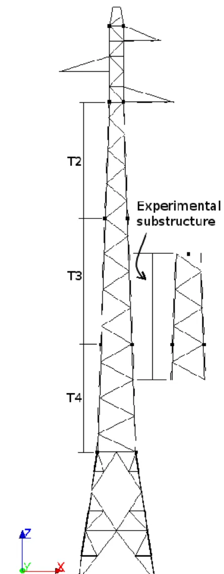
Lattice towers numerical models are not easily reduced to a small number of degrees-of-freedom (DOFs), and therefore, a strategy needed to be developed to correctly partition the experimental and numerical substructures. The proposed method consists of: 1) predict the potential failure modes of the tower using a numerical model of the complete structure; and 2) isolate an experimental substructure (see Figure 1) for which the failure mode and the ultimate load obtained is the same as for the complete tower. The method is explained in details in Section 3. The physical substructure identified in step 2) is then placed in an experimental test set-up as shown in Figure 2. The experimental test set-up is built such that hydraulic actuators can impose displacements/rotation, and measure corresponding forces/moment along three in plane DOFs, i.e., vertical and horizontal translations, and rotation, by mean of the transfer beam identified in Figure 2. This approach is based on the hypothesis that there is of a rigid plane at the interfaces between the experimental and numerical substructures, and that the transfer of forces/moment and displacements/rotation between the numerical and experimental substructures can be simplified to only three DOFs. The proposed method can be applied to a substructure located at one extremity of the tower (e.g. a crossarm or the tower base), but also to any intermediate vertical section along the height of the tower. In the latter case, the displacements/rotation applied to the experimental substructure are relative to both ends of the experimental substructure. The hybrid tests are conducted using three different subsystems. Firstly, the finite element software Code_Aster [6] is used to build the matrices in Equation 2 and to perform the time integration scheme. Secondly, the experimental test set-up is controlled using a MTS Flextest controller. Finally, a Labview [7] program and a National Instrument CompactRIO controller is used to manage the interactions between the numerical and experimental interfaces.
4
Figure 1: Lattice tower studied and identification of an experimental substructure.
5
3. IDENTIFICATION OF EXPERIMENTAL SUBSTRUCTURE
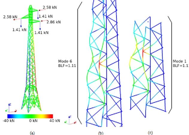
As described in the previous section, a numerical model of the complete tower was needed to identify the experimental substructures to be tested. The geometry and member types of the tower were selected in order to represent as closely as possible those of a tower commonly used by French utility RTE, but reduced to a 1:4 scale. As a first step, the nominal loading pattern presented in Figure 3(a) was used for a static linear elastic finite element analysis that did not account for second order geometrical effects. The model was constructed in the software Code_Aster [6] using elastic beam elements. Leg members and crossarms were rigidly connected, whereas diagonal and horizontal members were considered perfectly hinged. The method used for the development of the tower geometry is the one developed by Bouchard [2]. Although this feature was not strictly necessary for the static analysis, it allowed to include eccentricities in the connections through the use of rigid links. The tension and compression forces in each members were compared with their resistance as calculated using ASCE10-97 [9] standard. This comparison served as a preliminary identification criteria of the critical failure modes of the tower. It also allowed to show that compression failure modes were more critical than tension failure modes. This further justified the use of hybrid simulations because buckling modes are difficult to reproduce accurately numerically.
Figure 3: (a) Static analysis of the tower under nominal loads; (b) identification of buckling mode leading to global failure of the tower; and (c) substructure selected for the hybrid test.
As a second step, a linear elastic second order buckling analysis was performed to identify elastic buckling modes and the load level at which they occur. For each potentially critical failure modes that were identified in the previous first order static analysis, the elastic buckling stress obtained was used directly with the elasto-plastic buckling curve of ASCE10-97 to calculate a buckling load factor. This buckling load factor represents the factor to apply to the nominal load shown in Figure 3 (a) to obtain the failure in compression of a member for a given mode. This procedure is based on the work of Bouchard [8]. It allows following the elasto-plastic buckling curve given in ASCE10-97, while considering the eccentricity and rotational stiffness of connections defined in the model for the
6
evaluation of the elastic buckling stress. Next, the same procedure was applied to a subsection of the tower as shown in Figure 3 (c). This subsection was reduced to the minimum dimensions that still allow to reproduce correctly the buckling mode and corresponding buckling load factor. In Figures 3 (b) and 3 (c), the buckling load factor is defined with the symbol BLF.
4. EXPERIMENTAL TESTS ON COMPLETE TOWER
The complete 1:4 scale tower has a total height of approximately 8 m. It was tested up to failure by applying the load case presented in Figure 3(a). The vertical loads were applied using dead weights and kept constant throughout the experiment. The transverse loads were applied gradually using three independent systems of cables, pulleys and winches. Load cells were used to monitor the applied forces. Figure 4 shows the loading apparatus located in the structural laboratory at Université de Sherbrooke. The same complete 1:4 scale tower test was performed twice on distinct test specimens. Each test exhibited a distinct buckling failure mode that occurred at two different locations within the towers’ main body. The failure in Tower 1 occurred in section T2 at a height of 5.2 m (see Figure 1). In Tower 2, the failureoccurred in section T3 at a height of 3.5 m (see Figure 1). The numerical model presented in Section 3 confirmed that load levels corresponding to buckling modes that occurred in each section were within a relative difference of 13%. Based on this fact, it was decided that hybrid tests on both sections, i.e., sections T2 and T3, should be performed in order to access the performance of the hybrid testing procedure to reproduce the buckling failure modes and load-deformation behaviour observed during the complete tower reference tests. In this paper, only the results from the hybrid tests on section T3 are presented.
Figure 4: Experimental test set-up of the complete 8 m tower test: (a) aerial view; (b) view in perspective.
7
5. HYBRID TESTS
Applying the testing procedure explained in Section 2, two hybrid tests were performed on section T3 (see Figure 1). The 1.7 m experimental substructures used for both tests were identical. As in the case of the corresponding complete 1:4 scale tower reference test, the vertical loads were kept constant, while transverse loads were applied at a linear rate to the numerical substructure. The corresponding computed interface displacement and rotations were imposed to the physical substructure by mean of the test set-up presented in Figure 2.
Figure 5 shows pictures of the failure modes that were observed during the reference test and the hybrid tests (H1 and H2). It can be observed that similar buckling modes occurred in each test. In Figure 5, longitudinal strain measurements taken in compressed members where buckling occurred are presented. Comparing the results in hybrid tests H1 and H2, to the reference test results, it can be concluded that the same failure mode was observed in all cases. Being located in the compression truss plane, both legs are subject to the same load, but the model predicted slightly different buckling loads due to the position of the diagonals. For these particular tests, it can be concluded that the proposed hybrid testing procedure can successfully reproduce the failure modes observed during the reference tower test.
Reference test Hybrid test #1 (H1) Hybrid test #2 (H2)
Figure 5: Buckling modes observed in reference and hybrid tests and variation of strain measured in leg members during the tests.
Figure 6 shows the maximum values obtained at failure of: the total base shear load, the total overturning moment on the tower, and the strain in the members where buckling was initiated. A maximum difference of 15% was observed for the overturning moment between test H1 and the reference test. Base shear load differences with respect to the reference test are within 10% for both hybrid tests. It appears in this particular case that the proposed hybrid testing method is adequate for the evaluation of the failure mode and load of the lattice tower.
8
Figure 6: Comparison between reference and hybrid tests for global shear load and overturning moment, and strain in leg members.
6. CONCLUSIONS
A novel hybrid simulation method adapted for lattice towers testing was developed in this study. Two 1.7 m high sections of an 8 m high 1:4 scale lattice tower were tested in a laboratory environment whilst the remainder of the tower was modelled numerically. The tower sections to be tested during the hybrid tests were identified based on purely numerical simulations. The hybrid tests’ results were compared to the reference test results from a complete tower test.
The hybrid tests yielded failure modes and failure loads that were in agreement with the complete tower experimental test. The test result were also coherent with the numerical models’ results. Hybrid tests on other sections of the tower need to be presented to further validate the proposed approach. A next step of this research program will be to adapt the methodology for testing full-scale tower sections. Further research is also needed to implement this method for the study of dynamic loading on transmission lines.
ACKNOWLEDGEMENTS
The authors would like to acknowledge the financial support of RTE, Hydro-Québec, and the National Sciences and Engineering Research Council of Canada (NSERC). Material for the tower specimens was provided by Hydro-Québec. The contribution of Pierre-Luc Bouchard for the numerical modelling and Hervé Ducloux for discussions regarding tower testing is also acknowledged.
BIBLIOGRAPHY
[1] V. E. Saouma, M. V. Sivaselvan “Hybrid Simulation: theory, implementation and applications” (Balkema-proceedings and monographs in engineering, water and earth sciences, Taylor & Francis, London; New York, 2008, 226 pages)
[2] S. N. Dermitzakis, S. A. Mahin “Development of Substructuring Techniques for On-line Computer Controlled Seismic Performance Testing” (Technical Report, Earthquake Engineering Research Center, College of Engineering, University of California, 1985)
[3] A. Pinto, P. Pegon, G. Magonette, J. Molina, P. Buchet, G. Tsionis “Pseudodynamic test on a large-scale model of an existing RC bridge using non-linear substructuring and asynchronous motion” (Technical Report, European Commission Joint Research Centre, Institute for the Protection and Security of the Citizen, European Laboratory for Structural Assesment, 2002) [4] T. Y. Yang, B. Stojadinovic, J. Moehle “Hybrid simulation of a zipper-braced steel frame under
earthquake excitation” (Earthquake Engineering & Structural Dynamics Vol. 38(1), 2009, pages 95-113)
[5] C-P Lamarche, A. Bonelli, O. S. Bursi, R. Tremblay “A Rosenbrock-W method for real-time dynamic substructuring and pseudo-dynamic testing” (Earthquake Engineering & Structural Dynamics Vol. 38(9), 2009, pages 1071-1092)
9
[6] Code_Aster (www.code-aster.org, 2015)
[7] National Instruments, Labview (www.ni.com, 2015)
[8] P-L Bouchard “Calcul de la capacité de pylônes à treillis avec une aproche stabilité (Master thesis, Université de Sherbrooke, Canada, 2013)
[9] ASCE “Design of Latticed Steel Transmission Structures (ASCE 10-97)” (American Society of Civil Engineers, Reston, VA, USA, 1997)