HAL Id: inria-00614538
https://hal.inria.fr/inria-00614538
Submitted on 29 Aug 2011
HAL is a multi-disciplinary open access
archive for the deposit and dissemination of
sci-entific research documents, whether they are
pub-lished or not. The documents may come from
teaching and research institutions in France or
abroad, or from public or private research centers.
L’archive ouverte pluridisciplinaire HAL, est
destinée au dépôt et à la diffusion de documents
scientifiques de niveau recherche, publiés ou non,
émanant des établissements d’enseignement et de
recherche français ou étrangers, des laboratoires
publics ou privés.
Joint Source-Protocol-Channel Decoding: Improving
802.11N Receivers
Cagatay Dikici, Anissa Mokraoui, Michel Kieffer, Pierre Duhamel
To cite this version:
Cagatay Dikici, Anissa Mokraoui, Michel Kieffer, Pierre Duhamel. Joint Source-Protocol-Channel
De-coding: Improving 802.11N Receivers. European Signal Processing Conference, Aug 2011, Barcelone,
Spain. �inria-00614538�
JOINT SOURCE-PROTOCOL-CHANNEL DECODING:
IMPROVING 802.11N RECEIVERS
C
¸ a˘gatay Dikici
1, Anissa Mokraoui
2, Michel Kieffer
1,3, Pierre Duhamel
11L2S, CNRS – SUPELEC – Univ Paris-Sud, 3 rue Joliot-Curie, F-91192 Gif-sur-Yvette
2L2TI, Institut Galil´ee – Universit´e Paris 13, 99 Av. J.-B. Cl´ement, F-93 430 Villetaneuse
3on leave at LTCI, CNRS – Telecom ParisTech, 46 rue Barrault, F-75 013 Paris
{dikici,duhamel,kieffer}@lss.supelec.fr; {mokraoui}@univ-paris13.fr
ABSTRACT
This paper combines joint protocol-channel (JPC) and joint source-channel (JSC) decoding techniques within a receiver in the context of wireless data transmission. It assumes that demodulation and channel decoding at physical (PHY) layer can provide soft in-formation about the transmitted bits. At each layer of the protocol stack, JPC decoding allows headers of corrupted packets to be re-liably decoded and soft information on the corresponding payload to be forwarded to the correct upper layer. When reaching the ap-plication (APL) layer, packets may still contain errors and are JSC decoded, exploiting residual redundancy present in the compressed bitstream, to remove part of the residual errors. The main contribu-tion of this paper is to show that these tools may be efficiently com-bined to obtain i) reliable protocol layers permeable to transmission errors and ii) improved source decoders. Performance is evaluated using an OMNET++ simulation for the transmission of compressed HTML files (HTTP 1.1) over a standard RTP/UDP-Lite/Ipv6/MAC-Lite/802.11n-PHY protocol stack, only the receiver is modified. For a given packet error rate, the proposed scheme provides gains up to 2 dB in SNR compared to a standard receiver.
1. INTRODUCTION
The widely used OSI layered model partitions networking tasks into distinct layers [16]. This facilitates network design, since each layer has not to be aware of the information introduced by other layers, allowing heterogeneous contents to be delivered via the same com-munication network. Moreover, each layer, assuming that the lower layers behave perfectly, attempts to provide perfect information to the upper layers. For that purpose, error-detecting codes (CRC or checksums) protecting essentially headers (and sometimes the pay-load) have been introduced at various places of the protocol stacks. They are combined with retransmission mechanisms (when feasi-ble) for data packets deemed as corrupted. Moreover, since the layers work independently, but sometimes require the knowledge of identical (or correlated) information, some redundancy may be found, essentially in the packet headers that are processed at each layer. This redundancy has been recognized and used for example in ROHC [6] for reducing the header lengths. However, this redun-dancy can also be used for a better reception of the headers, there-fore reducing the number of rejected (and possibly retransmitted) packets.
The role of Joint Protocol-Channel (JPC) decoding is to make an efficient (and joint) use of the redundancy present in the protocol layers as well as the redundancy introduced by the channel cod-ing in order to obtain optimal receiver performance. Recently, JPC decoding techniques have been applied to perform Reliable Packet Header Estimation (RPHE) [17, 21, 19, 20]. Using JPC decoding, corrupted packets, which would be dropped at intermediate layers of the protocol stack by classical receivers, now may reach the APL layer [15, 22]. Even if they are still corrupted, the residual redun-dancy present in the compressed bitstream may be exploited by JSC decoding techniques to remove residual errors, see [10] and the
ref-erences therein. These techniques do not need any change in the structure of the transmitted signal, since JPC and JSC decoding is performed within the receiver. The ability to use these tools in the context of existing standards makes it potentially very practical.
However, to the best of our knowledge, the performance gains obtained when implementing simultaneously JPC and JSC decod-ing techniques have not yet been evaluated in a realistic receiver. Several issues have to be addressed. First, soft-output demodula-tors and channel decoders [5] have to be used to get soft informa-tion about the transmitted packets (a posteriori probabilities or log-likelihood ratios). RPHE has to be performed at each layer of the protocol stack. Soft bit information has to be transmitted between layers of the protocol stack [22]. Aggregated packets have to be re-liably delineated [7, 3]. Finally, JSC decoding has to be performed at APL layer.
This paper addresses several of previously mentioned issues and considers the reliable transmission of source-coded contents en-capsulated in RTP/UDP-Lite/IPv6/MAC-Lite/PHY-802.11n head-ers over an AWGN channel with Rayleigh fading. Soft demodu-lation and channel decoding, RPHE in all protocol layers, transmis-sion of soft information between layers, and JSC decoding of com-pressed HTML files [11] have been implemented in an OMNET++ simulator [25].
Section 2 briefly recalls the principles involved in JPC decoding for RPHE and in JSC decoding. Section 3 introduces the considered protocol stack in which JPC and JSC decoding have been imple-mented, as described in Section 4. Simulation results are reported in Section 5 before drawing some conclusions in Section 6.
2. JOINT PROTOCOL-CHANNEL AND SOURCE-CHANNEL DECODING
This section briefly recalls estimation techniques used to perform JPC decoding for RPHE within the protocol stack and JSC decoding at APL layer. See [10] for more details.
2.1 JPC decoding
At any layer L of the protocol stack, packets have more or less the same structure. For example, the n-th packet at layer L consists of a header hnand a payload xn. The header hnmay be partitioned into
up to four fields (not necessarily contiguous), depending on their properties. The constant field kncontains all bits which either do
not change from one packet to the next one (they are fully deter-mined by the standard) or which may be perfectly predicted from previously correctly decoded headers (from layer L or from other layers). The unknown field uncontains data which cannot be
pre-dicted but are important for the correct processing at Layer L. The protocol may be such that the values taken by unare restricted to
a set Ωn, where Ωn is determined from the various sources of
re-dundancy of the protocol stack. All bits of the header which are not fully determined and are not instrumental for the processing of the packet at Layer L are gathered in the other field on. Finally,
from some or all previously mentioned bits and (possibly) from the
packet payload xnby some (CRC or checksum) encoding function
cn= f (k, un, on, xn) . (1)
Assume that soft bit information y = [yk, yu, yo, yx, yc] has
been provided to Layer L on the header fields and on the payload by the channel decoder of the PHY layer or by Layer L − 1. The RPHE considered in [19, 20] consists in evaluating the MAP estimate
b
un= arg max
u∈Ωn
p(u|k, y) (2)
of untaking into account k and the soft information y. Assuming
that the HEC does not consider xnand that all u ∈ Ωnare equally
probable a priori, one gets b
un= arg max
u∈Ωn
p(yu|u)
∑
op(o) p (yo|o) p (yc|f (k, u, o)) (3)
A reduced-complexity optimal algorithm for evaluating (3) with a complexity O(` (on) 2`(cn)), where ` (z) is the length of the vector z,
has been proposed in [19] when the HEC is a CRC and in [20] when it is a checksum. Suboptimal algorithms achieving a complexity-efficiency trade-off have also been proposed in [19, 20].
Once unhas been estimated, the header may be processed at
Layer L and yx, containing the soft information about the bits of the
packet at layer L + 1 is forwarded to that layer. Floating-point num-bers to represent soft information may be forwarded between layers. When Log-likelihood ratios (LLRs) are transmitted, quantized LLR values on 3 or 4 bits are accurate enough and significantly reduce memory requirements, see [22].
Note that no JPC decoding is performed on packets which CRC or checksum is valid. The more complex JPC decoding process is only applied to packets which header has been deemed as erroneous. With good channel conditions, JPC is then only seldom used. 2.2 JSC decoding
Assume that the n-th packet has reached the APL layer, where it has to be processed by the source decoder. This packet may still contain errors, since CRCs and checksums at lower layers have been used to help RPHE. The decoded content dnhas to be reliably estimated.
It corresponds to the payload xAPLn for which soft bit information
yAPL
x,n is provided by the lower protocol layer. For that purpose,
residual redundancy left by the source coder in the compressed bit-stream may be exploited. This redundancy may come from the syn-tax of the codewords, the semantic of the bitstream, and from the packetization process, see [10]. This redundancy translates into the fact that xAPL
n can only take a limited number of values within a set
denoted as Ωxn. A MAP estimate of x
APL
n may then be obtained
from yAPP
xn and Ωxnas
b
xAPLn = arg max
x∈Ωxn
P(x|yAPPx
n ) (4)
In some cases, it is possible to structure the sequences belonging to Ωxnwith a multi-dimensional trellis. Efficient channel-decoding
techniques such as the Viterbi or BCJR algorithms [5] may then be employed to evaluatebxAPLn . With content-adaptive data compres-sion techniques, such as the CABAC, the CAVLC, or the deflate al-gorithm [8], the number of states of the trellis may be prohibitively large. Nevertheless, in such cases, it is usually possible to determine whether a sequence x does not belong to Ωxnor does not correspond
to a prefix of a sequence in Ωxn. This allows to use decoding
algo-rithms such as the stack or the M-algorithm [4].
Iterative decoding may be considered when it is possible to get extrinsic information at APL layer, which is easy when the BCJR decoder is used. Soft output sequential decoders such as the soft-output M-algorithm (SOMA) [26] or the soft-soft-output stack algorithm
RTP payload Deflate compression
Zlib head. Zlib tail
HTML File RTP head. UDP payload UDP-lite head. Ipv6 payload Ipv6 head. MAC-lite payl.
MAC-lite head. MAC-lite CRC
L-SIG HT-SIG PHY payload Pad
L-SIG HT-SIG trainingHT PHY payloadCoded Non HT training Pad Rate 1/2 CC BPSK + Interl. Scrambling Rate 1/2 CC BPSK + Interl. APL layer RTP layer UDP layer IP layer MAC layer PHY layer
Figure 1: Encapsulations on top of 802.11n
[23] may also be employed. The role of the outer code may be played by a CRC or a checksum, e.g., at UDP layer or by the channel code at PHY layer. The price to be paid in the second case, is a large amount of additional soft information and decoded headers which have to be forwarded to the APL layer.
3. CONSIDERED PROTOCOL STACK
JSC decoding of various types of data has been considered: still images, video, audio, and HTML files. In this paper, we consid-ered the transmission of HTML files over an 802.11n WiFi network [2], with an RTP/UDP-Lite/Ipv6/MAC-Lite/802.11n-PHY
encap-sulation, see Fig. 1. Clearly, HTML is usually combined with
TCP/IP, but RTP/UDP/IP facilitates the implementation of a per-meable protocol stack (thanks to UDP-lite [18]), since no retrans-mission of erroneous packets has to be considered at UDP layer, contrary to the connection-oriented TCP. Moreover, this may also give some insights on the behavior of the combination of JSC de-coders of video contents after JPC decoding.
3.1 Transmitter side
At transmitter side, the APL layer compresses the HTML file with deflate [8] and supplements the data with the appropriate Zlib header and tail information [9]. The packet is then delivered to the RTP layer. In order to specify the compressed HTML content, the RTP layer fixes the 7 bits of the payload type field value to an unassigned value in [24] (between 35 and 71).
The UDP-Lite layer [18] encapsulates the RTP packet specify-ing the source port and destination port fields, such that the source portcorresponds to the HTTP port 80, and the destination port to a value which is not known at the receiver, The checksum coverage field is fixed to 24 (bytes): the 16 bits of the checksum covers the 8 bytes of the UDP-Lite header and the 16 bytes of the considered RTP header. Then, the IPv6 layer adds the appropriate addressing and header information. Here, it is assumed that the source and des-tination are located in the same subnetwork hence the first 12 bytes of the IPv6 source and destination addresses are identical. Accord-ing to the UDP-lite specifications [18], the IPv6 pseudo-header is protected by UDP-checksum, which corresponds to the source and destination IPv6 addresses [12].
The MAC-Lite layer is a MAC layer [2] where the 32 bit MAC CRC covers only the 802.11n MAC header.
At PHY layer, IEEE 802.11n defines three PHY frame formats. The HT-mixed (HT for High Throughput) format has been chosen since the packets are transmitted with a preamble which is com-patible with the legacy 802.11a/g. In HT-mixed format, the PHY
2 0 /4 0 B W SIGNAL TAIL STBC 0 3 Coverage of HT-SIG CRC
Rate Tail bits
L-SIG
0 23
0 R
Coverage of L-SIG parity bit
CRC Known Unknown HTLENGTH CRC MCS P Length HT-SIG-1 HT-SIG-2 Smooth. Not sound. Rsv one Aggr. LDPC Sh. GI Nb Exp Sp. Str
Figure 2: PHY header format in 802.11n standard
Bytes :2 2 6 6 6 2 6 2 4 0 -7955 4 Coverage of MAC-lite CRC CRC Known Unknown Frame Control Duration ID Address1 (source) Addr. 2 (dest.) Addr. 3 (rx node) Addr. 4 (rx node) Sequence control QoS control HT control Frame Body FCS header
Figure 3: MAC-Lite packet format
payload is first supplemented with 3 bytes Legacy Signal (L-Sig) header and 6 byte HT-Sig header [2, S-20.3.9.2].
The L-Sig and HT-Sig headers are encoded separately using a convolutional code with generator polynomials g0= (133)o, g1=
(171)o, and a block interleaving follows as described in [2, S-17.3.5].
The PHY payload is first scrambled [2, S-20.3.10.2]. Then a
Modulation and Coding Scheme(MCS) is chosen. Here it is for
6 Mbps corresponding to a rate 1/2 convolutional coding scheme with BPSK modulation. The PHY packet is finally interleaved. A
Multiple Input Multiple Output(MIMO) model with 2 transmitter
and 2 receiver antennas is used to transmit the PHY packets over a Rayleigh fading channel.
In this paper, we assume that medium reservation is per-formed via Carrier Sense Multiple Access with Collision Avoidance (CSMA/CA) [2, S-9.2.5]. The transmitter sends a Request To Send (RTS) packet before sending information. If the receiver is not busy, it responds with a Clear To Send (CTS) packet to notify that: i) the transmitter can send the information and ii) all other stations of the same network are informed that the receiver is unavailable.
4. REDUNDANCY
The aim of this section is to specify the transmission conditions in order to identify the fields in the various headers which content is known, predictable, or unknown.
Assuming that the CSMA/CA medium reservation succeeds, the receiver has many information about the access point to which it is connected, the duration of the packet it will receive, etc. 4.1 802.11n Physical Layer
A 1 bit parity field covers the L-SIG header, whereas the HT-SIG header has a 7 bit CRC field. In L-SIG, the Rate field and the Re-servedbit are known to the receiver. The receiver has then to esti-mate the 12 bits of Length in L-SIG, the 7 bits of MCS and 16 bits of
HTLengthin HT-SIG (see Fig.-3). Since the three unknown fields
are related, RPHE is performed jointly on L-SIG and HT-SIG head-ers using a CRC-based correction algorithm as described in [19, 13].
4.2 MAC-Lite Layer
As explained in Section 3, the MAC-Lite CRC covers only the MAC header. Considering a non-encrypted downlink transmission of ordered MAC data packets with deactivated retransmission and power-save mode, the 2-byte Frame Control field is assumed to be known. The 6-byte Address2 field contains the MAC address of the receiver and is thus known. The 6-byte Address1 and Address3 are transmitted during the medium reservation procedure (RTS-CTS) and may be totally deduced by the receiver. Assuming that the ac-cess point is connected to a single router and that the router address has been already received in other information packets, the 6-byte Address4field may also be predicted by the receiver. The 2-byte
Se-quence Controlfield contains two parameters: a sequence number
and a fragment number. The sequence number represents the value of the current IP packet counter. The fragment number indicates the value of the current MAC data packet counter. In this study, packets are transmitted in order and these parameters can be easily determined: the sequence number is incremented by one for each RTS-CTS and the fragment number is incremented by one for each received MAC data packet, hence can be estimated by the receiver. The last field of the MAC header is reserved for local wireless net-works and is composed of 6 bytes of zeros in this study.
Thus, the receiver only estimates the following unknown field (See Fig. 3): 16 bits DurationID using RPHE based on the CRC field, as in [19].
4.3 RTP, UDP-Lite and IPv6 layers
R T P H e ad er Timestamp V X 0 4 8 12 P ad CC M
Synchronization Source Identifier
Contributing Source Identifier
IP
H
ea
d
er
Payload Length Next Header
1516 31
Hop Limit 0
Version Traffic Class Flow Label
Source Address Destination Address 0 4 8 12 16 20 28 24 32 36 U D P H e ad er Source Port Checksum Coverage C o v e r a g e o f U D P C h e c k s u m 0 4
Checksum Known Unknown Checksum
Payload type Sequence Number Destination Port
Figure 4: IPv6, UDP-Lite, and RTP header formats Since in the encoding scheme, the concatenation of the RTP, UDP-Lite, and pseudo-IPv6 headers is protected with a 16 bit checksum introduced by the UDP-Lite header [18]. RPHE of the headers introduced by the three layers is done jointly. The receiver
determines the known fields using inter and intra-layer redundancy and estimates the following unknown fields (see Fig. 4): the last 32 bits of the Source Address field of IPv6, the 16 bits of Destina-tion Portof UDP-Lite, the 7 bits of Payload type, and the 16 bits of Sequence number introduced by the RTP layer. The decoding algorithm based on the checksum field may be found in [20]. 4.4 Application Layer
From the RTP layer, the receiver knows that the packet it receives contains a compressed HTML file. The decoded file has to be com-pliant with the HTML syntax as specified in [1]. The set Ωxn
in-troduced in Section 2.2 contains thus all encoded sequences which could be produced by a compliant HTML page provided in [1]. Based on this a priori information and on the soft information pro-vided by the lower layers of the protocol stack, a JSC decoder in-volving a modified soft-output M-algorithm is employed. Iterative decoding with the channel decoder at APP layer is performed, see [14] for more details.
5. SIMULATION RESULTS
This section evaluates the performance of the JPC and JSC decoding schemes previously described via a simulation using OMNET++ [25]. JPC decoding is only performed on packets which CRC or checksum is not valid.
5.1 Channel model
We assume that if the transmitted signal is p, the received signal is y = Hp + n, where H is the complex channel response matrix which is assumed to be known at the receiver, and n is a complex-value Gaussian noise distributed asC N (0,σ2I).
5.2 Performance of JPC decoding
The RPHE performance at each layer of the protocol stack is eval-uated for several values of Eb/N0. The header error rate as a
func-tion of Eb/N0 is given for the PHY, MAC-Lite, IPv6, UDP-Lite,
and RTP layers. For each value of Eb/N0, enough simulations have
been performed to get 100 erroneous headers.
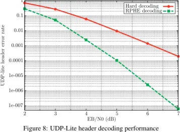
For a target packet error rate of 10−3, JPC decoding for RPHE provides a gain of 1.1 dB for the PHY layer header (see Fig. 5), 2.1 dB for MAC-Lite layer (see Fig. 6), 2.3 dB for IPv6 layer (see Fig. 7), 1.8 dB for UDP-Lite layer (see Fig. 8), and 1.9 dB for RTP layer (see Fig. 9) all compared to a classical decoding scheme.
5.3 Performance of JSC at APL layer
The worldcup.html html file test is available at
www.forum.nokia.com/tools. In a first step, as in [14], we
assume that all headers of the lower protocol layers were without
errors. Therefore, the performance of the HTML file recovery
alone is determined, using a plot of the HTML symbol error rate (SER) as a function of Eb/N0, see Fig. 10. For a target SER of
10−4, the JSC decoding algorithm achieves 0.8 dB gain compared to a standard decoder, see Fig. 10.
Fig. 11 provides the SER at APL layer when JPC has been em-ployed on the noisy packet headers at all layers.
1. RPHE and JSC decoding at APL layer; 2. RPHE and classical decoding at APL layer;
3. Classical header processing and JSC decoding at APL layer; 4. Classical header and APL layer decoding.
In average, JPC and JSC decoding provides an improvement of 0.6 dB compared to classical header and APL layer decoding.
Fig. 11 shows that for Eb/N0 between 5 dB and 7 dB, the
per-formance of the robust receiver (RPHE and JSC decoding at APL layer) is better then that obtained by the other three methods. For Eb/N0above 7 dB, RPHE and classical header processing perform
similarly when combined with JSC decoding. Moreover, the results in terms of SER are similar to those in Fig. 10 where all headers were assumed error-free.
1e-006 1e-005 0.0001 0.001 0.01 0.1 1 2 3 4 5 6 7
PHY header error rate
EB/N0 (dB)
Hard decoding RPHE decoding
Figure 5: PHY header decoding performance
1e-006 1e-005 0.0001 0.001 0.01 0.1 1 2 3 4 5 6 7
MAC-lite header error rate
EB/N0 (dB)
Hard decoding RPHE decoding
Hard decoding RPHE decoding
Figure 6: MAC-Lite header decoding performance
6. CONCLUSION
This paper combines JPC and JSC decoding techniques in a realistic communication context. Within the protocol stack, gain of up to 2 dB may be obtained with JPC decoding techniques compared to classical processing. At APL layer, JSC decoders provide a gain of about 0.8 dB in channel SNR. The gain is moderate due to the little redundancy left in compressed HTML files.
These results are directly applicable to other types of contents: speech, music, or video. JPC and JSC decoding reduces the need for retransmission of damaged packets. Moreover, they are compat-ible with the existing layered structure of a wireless communication network avoiding therefore modifications of the transmitters.
1e-007 1e-006 1e-005 0.0001 0.001 0.01 0.1 1 2 3 4 5 6 7
IPv6 header error rate
EB/N0 (dB)
Hard decoding RPHE decoding
Hard decoding RPHE decoding
1e-007 1e-006 1e-005 0.0001 0.001 0.01 0.1 1 2 3 4 5 6 7
UDP-lite header error rate
EB/N0 (dB)
Hard decoding RPHE decoding Hard decoding RPHE decoding
Figure 8: UDP-Lite header decoding performance
1e-007 1e-006 1e-005 0.0001 0.001 0.01 0.1 1 2 3 4 5 6 7
RTP header error rate
EB/N0 (dB)
Hard decoding RPH recovery Hard decoding RPHE decoding
Figure 9: RTP header decoding performance
REFERENCES [1] HTML 4.01 specification.
[2] IEEE standard for information technology–telecommunications and information exchange between systems–local and metropolitan area networks–specific re-quirements part 11: Wireless lan medium access control (mac) and physical layer (PHY) spec. amendt 5: Enhancements for higher throughput, 29 2009. [3] U. Ali, M. Kieffer, and P. Duhamel. Joint protocol-channel decoding for robust
aggregated packet recovery at WiMAX MAC layer. In Proc. IEEE SPAWC, pages 672 – 676, Perugia, Italy, 2009.
[4] J. B. Anderson and S. Mohan. Source and Channel Coding: An Algorithmic Approach. Kluwer, 1991.
[5] L. R. Bahl, J. Cocke, F. Jelinek, and J. Raviv. Optimal decoding of linear codes for minimizing symbol error rate. IEEE Trans. Info. Theory, 20:284–287, 1974. [6] C. Bormann, C. Burmeister, M. Degermark, H. Fukushima, H. Hannu, L.-E.
Jonsson, R. Hakenberg, T. Koren, K. Le, Z. Liu, A. Martensson, A. Miyazaki, K. Svanbro, T. Wiebke, T. Yoshimura, and H. Zheng. Robust header compres-sion (ROHC): Framework and four profiles. RFC 3095, 2001.
[7] M. Chiani and M. G. Martini. Optimum synchronization of frames with un-known, variable lengths on Gaussian channels. In Proc. IEEE GLOBECOM, pages 4087 – 4091, 2004.
[8] P. Deutsch. Deflate compressed data format specification version 1.3, 1996.
http://www.ietf.org/rfc/rfc1951.txt.
[9] P. Deutsch and J.-L. Gailly. Zlib compressed data format specification version 3.3, 1996. http://www.gzip.org/zlib/rfc-zlib.html.
[10] P. Duhamel and M. Kieffer. Joint source-channel decoding: A cross-layer per-spective with applications in video broadcasting. Academic Press, 2009. [11] R. Fielding, J. Gettys, J. Mogul, H. Frystyk, L. Masinter, P. Leach, and
T. Berners-Lee. Hypertext transfer protocol – HTTP 1.1. RFC 2616, The In-ternet Society, 1999.
[12] R. Hinden and S. Deering. Ip version 6 addressing architecture, 1998.
http://tools.ietf.org/html/rfc2373.
[13] Z. Jaoua, A. Mokraoui-Zergainoh, and P. Duhamel. Robust transmission of
1e-007 1e-006 1e-005 0.0001 0.001 0.01 0.1 1 10 2 3 4 5 6 7 8
Symbol error rate
EB/N0 (dB) Hard decoding Robust decoding, M=10
Figure 10: SER at APL layer with clean headers
1e-007 1e-006 1e-005 0.0001 0.001 0.01 0.1 1 10 2 3 4 5 6 7 8
Symbol error rate
EB/N0 (dB) Classical header and classical APL decoding
Classical header and JSC APL decoding RPHE and classical APL decoding Joint RPHE and JSC APL decoding Synchronization point
Figure 11: SER at APL layer with JPC decoding
802.11n physical packet headers. In Proc. SPAWC, pages 369–373, 2009. [14] Z. Jaoua, A. Zergainoh-Mokraoui, and P. Duhamel. Robust transmission of html
files: iterative joint source-channel decoding of Deflate codes. In Proc. EU-SIPCO, 2008.
[15] H. Jenkac, T. Stockhammer, and W. Xu. Permeable-layer receiver for reliable multicast transmission in wireless systems. In Proc. IEEE WCNC, pages 1805– 1811, 2005.
[16] J. F. Kurose and K. W. Ross. Computer Networking: A Top-Down Approach Featuring the Internet. Addison Wesley, Boston, third edition, 2005. [17] C. Lamy and S. M´erigeault. Method of correcting an erroneous frame by a
re-ceiver. patent WO03101028, Dec. 2003.
[18] L. A. Larzon, M. Degermark, L. E. Jonsson, and G. Fairhurst. The lightweight user datagram protocol (UDP-Lite). RFC 3828, The Internet Society, 2004. [19] C. Marin, Y. Leprovost, M. Kieffer, and P. Duhamel. Robust mac-lite and soft
header recovery for packetized multimedia transmission. IEEE Trans. on Comm., 58(3):775–784, 2010.
[20] F. M´eriaux and M. Kieffer. Robust IP and UDP-lite header recovery for pack-etized multimedia transmission. In Proc. IEEE Int. Conf. on Acoustics, Speech and Signal Processing, 2010.
[21] J. W. Nieto and W. N. Furman. Cyclic redundancy check (CRC) based error method and device. US Patent US 2007/0192667 A1, Aug. 16 2007. [22] G. Panza, E. Balatti, G. Vavassori, C. Lamy-Bergot, and F. Sidoti. Supporting
network transparency in 4G networks. In Proc. IST Mobile and Wireless Com-munication Summit, 2005.
[23] L. Perros-Meilhac and C. Lamy. Huffman tree based metric derivation for a low-complexity soft VLC decoding. In Proc. IEEE ICC, pages 783–787, 2002. [24] H. Schulzrinne and S. Casner. RTP profile for audio and video conferences with
minimal control, 2003. http://tools.ietf.org/html/rfc3551. [25] A. Varga. OMNeT++, chapter Modeling and Tools for Network Simulation.
Springer Verlag, 2010.
[26] K. K. Y. Wong. The Soft-Output M-Algorithm And Its Applications. PhD thesis, Queen’s University, Kingston, Canada, 2006.

![Figure 4: IPv6, UDP-Lite, and RTP header formats Since in the encoding scheme, the concatenation of the RTP, UDP-Lite, and pseudo-IPv6 headers is protected with a 16 bit checksum introduced by the UDP-Lite header [18]](https://thumb-eu.123doks.com/thumbv2/123doknet/12503951.340523/4.918.473.801.529.1044/figure-formats-encoding-concatenation-headers-protected-checksum-introduced.webp)