This is an author-deposited version published in:
http://oatao.univ-toulouse.fr/
Eprints ID: 11316
To link to this article: DOI: 10.1109/DASIP.2010.5706284
URL:
http://dx.doi.org/10.1109/DASIP.2010.5706284
To cite this version:
Dion, Arnaud and Boutillon, Emmanuel and
Calmettes, Vincent and Liegeon, Emmanuel A flexible implementation of a
Global Navigation Satellite System receiver for on-board satellite
navigation. (2010) In: Design and Architectures for Signal and Image
Processing (DASIP), 26 October 2010 - 28 October 2010 (Edinburgh,
United Kingdom).
O
pen
A
rchive
T
oulouse
A
rchive
O
uverte (
OATAO
)
OATAO is an open access repository that collects the work of Toulouse researchers and
makes it freely available over the web where possible.
Any correspondence concerning this service should be sent to the repository
administrator:
[email protected]
A FLEXIBLE IMPLEMENTATION OF A GLOBAL NAVIGATION SATELLITE SYSTEM
(GNSS) RECEIVER FOR ON-BOARD SATELLITE NAVIGATION
A. Dion
1, E. Boutillon
2, V. Calmettes
1, E. Liegon
31
Universite de Toulouse, ISAE, DEOS, TESA, Toulouse, France
ISAE, 10 Av. E. Belin, 31055 Toulouse Cedex 4, France.
{arnaud.dion, vincent.calmettes}@isae.fr
2
Lab-STICC, CNRS, Universite Europeenne de Bretagne, France
Centre de recherche, UBS, 56100 Lorient, France. [email protected]
3
Thales Alenia Space, France
26 Av. J-F. Champollion 31100 Toulouse, France. [email protected]
ABSTRACT
In this paper, we present the implementation of the acquisi-tion algorithm of a versatile Global Navigaacquisi-tion Satellite Sys-tem (GNSS) receiver for satellite applications. For versatil-ity purpose, the choice of the receiver algorithms has been motivated by 1) their capability to fulfill the application re-quirements with a moderate complexity, 2) their capability of being factorized in a small set of elementary modules that can be configured and combined in various ways in order to pro-cess both GPS and Galileo current and future signals. These algorithms have been specified using SystemC, a modeling language that can be common to hardware and software flow. The use of a virtual platform for simulation allows us to iden-tify bottleneck of the architecture and to propose algorithm modification to solve them.
Index Terms— GNSS algorithm, Co-design, Versatility, SystemC.
1. INTRODUCTION
This paper presents the current status of a project aiming to construct a flexible Global Navigation Satellite System (GNSS) receiver to be placed on board in a satellite. This receiver should be flexible in order to cope several types of GNSS signals (GPS, Galileo as well as future signal). It should also be able to give a position solution for different type of satellite mission (Low, Medium, Geostationary Earth Orbiter), each mission having different characteristics in term of Doppler excursion, range of SNR, mean duration of visi-bility of a GNSS satellite.
This project has been divided in 5 different phases: 1) def-inition of the system requirement for the different types of mission based on existing GNSS system [1], 2) selection and validation of acquisition algorithm using criteria of flexibil-ity, performance and low complexity [2], 3) selection of the architecture model and the associated design methodology, 4) design of the decoder, 5) chip conception and validation
before first lift-off on a satellite. At the moment, the project is in the middle of its fourth phase.
The objectives of this paper are double. First, it presents a design experience based on a hardware/software coherent developing environment allowing algorithm refinement from specification validation down to implementation. Second, it discuss the interaction between the selected architecture and the algorithm partition and configuration. Preliminary result are also given.
After a brief recall on GNSS signals, the second section de-scribes the acquisition process and the algorithm that will be implemented in order to acquire GNSS signals. This description shows the different stages involved in the acqui-sition process. The third section shows the necessary steps toward an effective implementation of the receiver. The de-sign methodology and tools used during this project are also presented. The fourth section presents the design and imple-mentation of the receiver acquisition algorithm. An example of early performance analysis and optimization shows the benefits of this design process. Finally, section five draws the conclusions and the perspectives.
2. ACQUISITION ALGORITHM 2.1. The GNSS L1 signals
The algorithm is adapted to process the GPS-L1 Coarse Ac-quisition (C/A) signal as well as the Galileo-E1 Open Ser-vice (OS) signal which are CDMA signals. Data are therefore modulated by a spreading code. For both signals, the expres-sion of the sampled complex signal at the input of the receiver can be defined by:
sn=
√
CD(n − τ)Se(n − τ)ej(ϕ0+2πfdnTs)+ nn (1)
Whereτ is the unknown code phase, C is the power of the signal,D ∈ [±1] is the data signal, Se∈ [±1] is the
spread-ing signal, ϕ0 is the carrier phase,fd is the unknown
resid-ual frequency after carrier wipe-off, Ts is the sampling
frequencyfd and the code delay τ are considered constant
over the coherent integration time. The GPS-L1 carrier fre-quency isfL1 = 1575.42 M Hz. The L1 C/A signal is
mod-ulated by a 1023-chip spreading code at a chip ratefCA =
1.023 M Hz, the pseudo-period is then 1 ms [4]. This signal is also named BPSK(1), takingfCAas reference frequency.
The data rate is50 b.s−1, one bit is therefore modulated by
20 spreading code sequences.
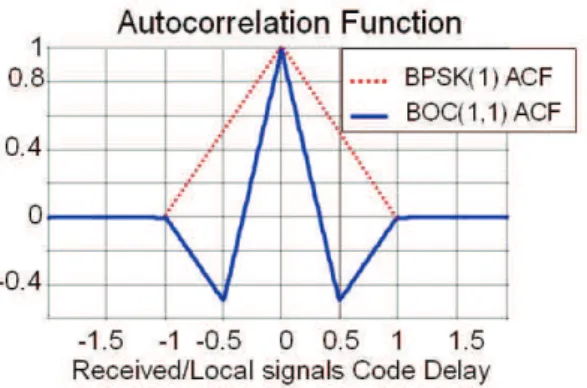
The Galileo-E1 signal is emitted at the same carrier frequency than GPS-L1. To accomplish the spectral separation from GPS C/A signal, the Galileo OS spreading code is modu-lated by a squarewave subcarrierscs(n). The signal
modu-lated by this sub-carrier is called BOC(n,m) (Binary Offset Carrier) withn = fsc/fCA andm = fc/fCA, where fsc
is the frequency of the sub-carrier andfcis the frequency of
the spreading code. The sharper auto-correlation peak (fig-ure 1) enables more accurate code tracking than with GPS C/A, and good multipath resolution. In order to further en-hance the tracking performances in the presence of multipath, Galileo OS signal is composed of 2 BOC signals: BOC(1,1) and BOC(6,1). Multipath is not a critical problem for space applications, we will therefore demodulate Galileo OS signal as a BOC(1,1). The correlation loss is thenLC = 0.84 dB [7]
but the number of computations will be be much smaller. The spreading code length is 4092 chips and the pseudo-period is then 4 ms. The data rate is250 b.s−1; thus each data value
multiplies a single pseudo-period of the spreading sequence. Moreover, a pilot channel is provided. This dataless chan-nel allows to increase the coherent integration time during the correlation process.
2.2. Signal acquisition
The purpose of the acquisition is to find a coarse estimation { ˆfd, ˆτ } of the unknown value {fd, τ }. The acquisition
pro-cess is then a two-dimensional (code delay and frequency) search for the correlation peak over an uncertainty region. The search along the code delay axis is performed for each
Fig. 1. ACF for BOC(1,1) and BPSK(1) signals sample of the spreading code. The sampling frequency is determined from the signal bandwidth and the receiver dy-namic. In order to reduce the transition phase, used for PLL
convergence, before tracking phase, the search precision has been fixed to1/4 chip for Low Earth Orbit (LEO) applica-tion. The sampling frequency is thenF s = 4.096 M Hz for GPS C/A andF s = 8.192 M Hz for Galileo OS (twice the spectrum bandwidth). Thus, the number of search bins along the time axis for GPS C/A and Galileo OS is respectively 4096 and 32768. The search precision has been fixed to1/2 chip for GEO application. Thus, the sampling frequency can be chosen equal to the spectrum bandwidth.
Along the frequency axis, the search is related to the receiver application. The Doppler frequency range is 84 KHz for a LEO mission, whereas it is 16 KHz for a Geostationary Earth Orbit (GEO) mission [1]. For both signal the coherent inte-gration time (Tcoh) is 8 ms and the frequency step is chosen
as [2]:∆f = 1/Tcoh = 125 Hz.
The search over the frequency axis (fd) is then performed
over84000/125 = 672 bins in case of LEO mission and 128 bins in case of GEO mission.
The threshold of the correlation decision is fixed to obtain a false probability equal to 10−3. The value of the
miss-detection probability depends on the C/N0 ratio. In the
frame of this study, the miss-detection probability must re-main smaller than10−1. This value can be easily reached in
the frame of LEO mission (see [2]). For GEO mission the integration process must be performed in two stages: 1) a coherent integration over a duration of 8 ms which is adapted to the frequency step and 2) a non-coherent integration in order to provide a miss-detection probability equal to10−1.
The correlation process is shown figure 2. A non-coherent square-law detector is added in order to eliminate the carrier signal after the coherent integration. The coherent integration time is obtained from N 1 × N2 samples where N1 is the number of samples over the spreading code sequence and N 2 is the number of spreading sequences over the coherent integration time. The total integration time isN 1 × N2 × N3 whereN 3 is the number of non-coherent integrations. For GEO mission, N 3 = 7 in order to acquire satellite with a C/N0= 30 dBHz [2].
Fig. 2. Acquisition process
Unlike GPS ACF, the BOC ACF has multiple peaks and the risk of wrong peak selection should be considered (see figure 1). The Sub-Carrier Phase Cancellation technique (SCPC) [6] has been implemented here in order to cope with this problem. To summarize this section, the main parameters of the acquisition module are shown in the table 1.
GPS/LEO GPS/GEO Galileo/LEO Galileo/GEO
N1 4096 2048 32768 16384
N2 8 8 2 2
N3 1 7 1 7
Table 1. Search Array size
2.3. Acquisition algorithm
The previous section shows how complex is the acquisition process. Fast acquisition approaches, based on the correla-tion by Fast Fourier Transform (FFT), could be used in order to reduce the delay of the acquisition processing. These meth-ods lead to reduce the number of arithmetic operations for the computation of the autocorrelation function. Thus, many de-signs use a one-dimensional FFT to explore the code delay axis (τ ) whereas the frequency axis (fd) is swept by frequency
translation.
We propose here a technique, based on a size scalable FFT in order to explore both dimensions (code delay and frequency) at once. The algorithm is described in [3], it leads to a re-duction of 50% of the number of computations for the search of 1 satellite, compared to the classic FFT method. Once the
Fig. 3. Correlator unit
N 1 × N2 × N3 samples have been collected over the inte-gration time, the following process is applied (see figure 3):
1. A FFT, stored in buffer X1, is performed on theN 1 × N 2 samples.
2. The buffer X2 is organized to provide N 2 columns of N 1 samples. Each column corresponding to one pseudo-sequence period. Let r2 be the index of the
columns withr2= 0..N 2 − 1 and r1= 0..N 1 − 1.
X2(r2, r1) = X1(r2+ N 2 × r1)
3. The correlation is performed in the frequency domain on theN 2 columns for N 2 values of the Doppler fre-quency.
4. N 2 inverse FFT of N1 points are performed in order to explore the frequency domain over a range equal to N 2 × 125 Hz (1KHz for GPS, 250Hz for Galileo). These two last stages must be iterated several times while shifting the local replica in order to cover the whole frequency domain. And the whole process is iteratedN 3 times for non-coherent integration.
Figure 4 presents the result of the algorithm applied on real signal. The signal detected is from GPS Satellite Vehicle
Number (SVN) 36. It has been acquired withN 1 = 4096, N 2 = 8, N 3 = 1 (LEO configuration) and the estimates { ˆfd, ˆτn} are {−3.625 KHz, 3024}.
The next section presents the design methodology that has
Fig. 4. Acquisition of GPS SVN36
been implemented in order to prototype this algorithm in a FPGA.
3. METHODOLOGY 3.1. Context
Core electronic components for satellite payloads are mainly ASICs and OTP (One Time Programmable) FPGA due to the constraints of space environment. One of the main draw-backs of these components is that they are not reconfigurable. Therefore, applications can’t be upgraded during the life span of the satellite, up to 20 years. Embedded proces-sors can provide reconfigurability and allow the designer to achieve high component integration. Although environments nowadays permit to perform transactional level modeling of hardware/software systems, none of them offers the possibil-ity to easily modify the architecture and migrate tasks from hardware to software (and vice versa) without recoding (due to the different languages) and to completely refine up to a hardware-software embedded product.
3.2. Versatility
The algorithms have been studied in order to find commonal-ities that could be factorized. Thus, we have reduced the nav-igation algorithms into a set of basic processing algorithms that can be configured and combined in various ways to build a signal processing chain for signal acquisition and tracking. Each of these processing modules can be configured with a small set of parameters, such as the length of the correlation. The idea is to implement a pool of modules that can be con-figured in order to form a processing chain. The real-time flexibility of the receiver will be ensured by on-the-fly uration of signal processing chains during mission. A
config-uration arbiter will select and configure available modules in order to build a chain for a specific signal.
3.3. design methodology and tools
In order to avoid tedious language conversions and time con-suming validation phases, the design language should be common to hardware and software flow. The higher level of abstraction would also lead to a reduction of design time. We have chosen SystemC, a set of C++ classes and macros, which is an emerging standard for the description of hard-ware models. High level synthesis tools, supporting C-based languages, are now available from EDA providers.
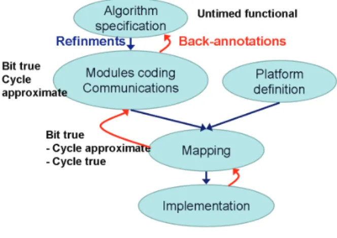
Fig. 5. Y approach
We have adopted the well-known ’Y’ approach which sepa-rates the application from the architecture (see figure 5). First, the receiver algorithms have been specified with SystemC on a software development tool : Microsoft VisualC++ Express. For architectural exploration down to prototyping, we have used Space Studio, a tool from Space Codesign Systems. This tool allows the designer to partition the algorithm into modules and to map these modules onto an architecture [8]. This architecture, also named virtual platform, consists of a set of IPs modeled at the transactional level. The aim of the methodology is to delay the choice of a partition as late as possible in the design flow. Simulation and implementation analysis are then available in order to help the designer to choose an architecture.
Once validated, the user modules have been synthesized with Catapult, a high-level synthesizer from Mentor Graphics. Space Studio generates a Catapult project for each module and Catapult offers then the possibility to analyze and explore the micro-architecture of hardware modules. Thanks to the flow, several architectures can be easily generated and com-pared.
The receiver has been prototyped on a Xilinx FPGA. Space Studio generates the Xilinx EDK project, which is then used to place/route and to program the component.
This design flow can be followed top-down for implemen-tation refinement or bottom-up for detailed simulations and
design space exploration. The next section presents the de-tails of the implementation of the acquisition algorithm.
4. IMPLEMENTATION OF THE ALGORITHM 4.1. Algorithm modeling
Due to the C++ syntax and the templates provided, Sys-temC allows the designer to achieve fast implementation of the algorithms. The purpose of this untimed functional (UTF) model, also named Programmer view (PV) model, is to validate the algorithms as well as to analyze the data flow between the various tasks. SystemC provides also data types, such as fixed point, the effects of the quantization on the computations can then be easily studied. The time can also been modeled with SystemC, as in VHDL or Verilog. Thus, time-dependent effects, such as the Doppler, can be precisely modeled. The algorithms has been validated using real GNSS signals captured by our L1 wide band radiofre-quency front-end. We have also used signals generated with Matlab and with a Spirent generator belonging to the CNES (French space agency) in order to simulate the specifities of space applications, such as the International Space Station (ISS) or the satellite Spot5. Once validated, the algorithms has been divided into modules, with Space Studio, in order to be mapped on an architecture.
The most difficult task was then to decompose the sequential application into modules in order to exhibit enough paral-lelism to exploit the concurrency offered by the architecture. The modules can be untimed (PV) or approximately timed, Programmer View Timed (PVT), for more realistic assess-ment of performances. The granularity of the partition should not be too small because each module will be implemented with at least one communication interface, to the bus or to another module. Then, many modules lead to many interfaces and a larger physical implementation. The aim was then to decompose the algorithm into large coherent modules with common configuration parameters. The micro-architecture of the modules would be optimized later with the high-level synthesis tool.
of standard busses, such as ARM AMBA or IBM CoreCon-nect. The communication is provided by simple functions that are independent of the channel or the implementation, software or hardware.
The acquisition algorithm is relatively straightforward, the 3 main modules are the variable-size FFT, the Correlator and the non-coherent Integrator (see figure 6). Due to the large number of data to process, the FFT has no local mem-ory. The samples have a dynamic of 4 bits and, due to the dynamic of the FFT, the internal computations are stored on 16 bits for real and imaginary parts. The local replicas of the spreading code are stored in an external ROM memory. The non-coherent Integrator module is able to process di-rectly GPS signals or to integrate In-Phase and Quadrature Galileo signals for SCPC technique (see section 2.2). The Acquisitionmodule controls the iterations of the acquisition algorithm for the search on the whole Doppler excursion and GNSS satellite constellation. The modules are scheduled by using blocking or non-blocking transactions. Finally, a con-trol module configures the computation modules for a given application.
The same sets of signals, used in the previous design phase, have been used to validate the partitioned algorithm. This model is bit-true and cycle-approximate (BTCA), and the purpose is to validate the partition, the communication and the synchronization between the modules.
Thanks to the debug and analysis tools, bus traffic can be analyzed early in this phase in order to find possible conges-tions. The early performance assessment allows the designer to modify the function or the architecture long before im-plementation phase, thus reducing the costs and the design time. One module was particularly time consuming: a de-tailed analysis of the transactions on the bus shows that the FFTmodule spent much more time on transactions than on computations, unlike other modules such as the Integrator. As the FFT is versatile, it has no internal memory. It has to processNs = N 1 × N2 × log2(N1 × N2) samples, that
means2 × Nsbus transactions (read and write).
We have then adopted a multi-level FFT architecture in order to reduce the number of accesses to the external memory. The FFT can be decomposed into successively smaller FFTs and multiplications with phase factors [9]: aK-point FFT (K = k1 × k2) can be decomposed into successively k2 FFT of k1 points and k1 FFT of k2 points. The optimized FFT is based on one flexible FFT module, able to process up to 512 (29) points stored in a local memory, with a phase rotator, and
one configuration module for the scheduling of the levels. For example, a 32768 (215) points FFT can then be decomposed
into a first level of 64 FFT512 (29), followed by a phase
rotation and a last level of 512 FFT64 (26). The number of
bus accesses performed by the FFT module is then reduced to4 × N1 × N2. The computation time of the FFT is divided by 3 in the case of a 32768 points FFT. The scheduling of a GPS C/A acquisition over 1 KHz is shown figure 7.
Fig. 7. Bus traffic analysis
The next phase was to define a virtual platform and to map the modules onto it.
4.2. Architecture definition and mapping
Due to the constraints of the space environment, the receiver will have to be implemented in an ASIC. However, in order to completely validate the design flow, the receiver will be prototyped in a FPGA. Space Studio propose an IP library for Xilinx FPGAs. Thus, the MicroBlaze and the OPB bus have been used for this implementation.
The most computationally intensive blocks, FFT, Correlator
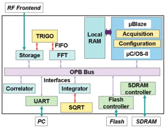
Fig. 8. Virtual Platform mapping
and Integrator, should be implemented on hardware and opti-mized with the high level synthesis tool. As shown on figure 8, the low level modules, Trigo and SQRT, are not connected to the bus, but directly to the modules with bi-directional FI-FOs. They don’t interact with the memories and the direct links are faster than the bus transactions. Control modules (Acquisition and Configuration) that could evolve during the
life of the satellite are implemented on processor and sched-uled by real time OS:µC/OS-II. The design flow facilitates mapping exploration. We have opted for the platform shown figure 8.
The next section presents the results of the implementation on a FPGA.
4.3. Implementation and FPGA prototyping
The acquisition modules have been prototyped on Xilinx Vir-tex2Pro FPGA : 2VP30. Space Studio generates the Cata-pult project files in order to synthesize the hardware mod-ules. The implementation of each module can be then pre-cisely controlled and analyzed. Once the modules synthe-sized, the latency of each modules can be interpreted from Catapult schedule view and then back-annotated in the Space Studio SystemC model. After this design phase, the simula-tions are cycle accurate, even for the hardware modules.
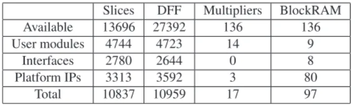
Slices DFF Multipliers BlockRAM
Available 13696 27392 136 136
User modules 4744 4723 14 9
Interfaces 2780 2644 0 8
Platform IPs 3313 3592 3 80
Total 10837 10959 17 97
Table 2. Used ressources
The acquisition system occupies 79% of the slices of a 2VP30 FPGA. As shown on table 2, the interfaces between user mod-ule and busses occupies 25% of the FPGA. This is mainly due to the 4 interfaces to the OPB bus of the main modules : Storage, FFT, Correlator and Integrator. As exposed in sec-tion 4.1, the granularity of user modules should not be too small in order to implement as few bus interfaces as possi-ble. Instead, the micro-architecture of the modules should be optimized with the high level synthesis tool. The platform oc-cupies 30% of the area. It is composed by a lot of small mod-ules, such as an UART, and the biggerµBlaze (1407 slices) or OPB bus (507 slices) and it can’t be optimized a lot further. On the other hand, user modules use 44% of the slices. These modules are clearly not optimized, more than 1200 slices are used for the Correlator module. The micro-architecture has not been studied yet, this is the on-going phase of the project. As an example, multipliers have been implemented on DFF whereas a lot of hardware multipliers are still available. The coding style is also important, a slight recoding of the FFT module has led to a reduction of the used resources from 2000 to 800 slices.
With a receiver clock frequency of 100 MHz, the duration of the search, for LEO application (84 KHz Doppler) with the GPS constellation (32 satellites), is 2 min 15 sec. As an ex-ample, the duration for ground application would be 13 sec with our receiver.
5. CONCLUSION
This study presents a technique to acquire GNSS-L1 signals in a receiver designed for space environment. Acquisition algorithm is proposed in order to process GPS and Galileo signals. The architecture of an acquisition system, based on 1 scalable FFT core, is described. A coherent co-design flow has been presented and the acquisition algorithm has been modeled on a virtual platform and implemented in a FPGA using this tool flow.
The high level language, common to hardware and software, allows the designer to easily modify the architecture and to adapt it to the functionality and the requirements. Com-pared to a conventional approach, the design time has been reduced to approximately 3 months, from SystemC specifica-tion down to implementaspecifica-tion, without prior knowledge of the tools. However, efforts should be made on coding style for hardware implementation in order to optimize the chip area. The on-going step of the implementation is the optimization of the micro-architecture with the high level synthesis tool, Catapult. Several architectures and module implementations will also be compared in term power consumption, latency and area.
6. REFERENCES
[1] A. Dion, E. Boutillon, V. Calmettes, ”Reconfigurable GPS-Galileo Receiver for Satellite-based Applications”, proc. of ION GNSS, Fort Worth, Texas, Sept., 2007. [2] V. Calmettes, A. Dion, E. Boutillon, E. Liegeon, ”Fast
Acquisition Unit for GPS/GALILEO Receivers in Space Environment”, proc. of ION National Technical Meeting, San Diego, Jan., 2008.
[3] D. Akopian, ”FFT based satellite acquisition methods”, IEEE Proc. Radar, Sonar and navigation, Vol. 152, No 4, August 2005, Pages 277-286.
[4] Navstar GPS Space Segment/Navigation User Interfaces (IS-GPS-200D), 2004.
[5] Galileo Open Service Signal in Space Interface Control Document (OS SIS ICD) Draft 1, 2008.
[6] V. Heiries, D. Roviras, L. Ries, V. Calmettes, ”Analy-sis of Non Ambiguous BOC Acquisition Performance”, proc. of ION GNSS, Long Beach, Sept., 2004.
[7] N. Hoult, L. E. Aguado, R. Crescimbeni,” Performance comparison of TMBOC and CBOC signals”, Proc. of CNES workshop on Galileo signals and signal process-ing, Toulouse, 2006.
[8] L. Filion, M-A. Cantin, L. Moss, G. Bois, E. M. Aboul-hamid, ”Space Codesign: A SystemC Framework for Fast Exploration of Hardware/Software Systems”, proceed-ings of DVCON, San Jose, Feb.,2007.
[9] G. Zhong, F. Xu, and A. N. Willson, Jr., ”A Power-Scalable Reconfigurable FFT/IFFT IC Based on a Multi-Processor Ring”, IEEE Journal of Solid-State Circuits, Vol. 41, pp. 483-495, Feb. 2006.