Any correspondence concerning this service should be sent
to the repository administrator: [email protected]
This is an author’s version published in:
http://oatao.univ-toulouse.fr/22436
Official URL
DOI : https://doi.org/10.33012/2018.15878
Open Archive Toulouse Archive Ouverte
OATAO is an open access repository that collects the work of Toulouse
researchers and makes it freely available over the web where possible
To cite this version:
Ortega Espluga, Lorenzo and Poulliat,
Charly and Boucheret, Marie-Laure and Aubault, Marion and Al
Bitar, Hanaa Co-design of message Structure and Channel Coding
Scheme to Reduce the Time to CED and to Improve the Resilience
for a Galileo 2nd Generation New Signal. (2018) In: 31st
International Technical Meeting of The Satellite Division of the
Institute of Navigation (ION GNSS+ 2018), 24 September 2018 - 28
September 2018 (Miami, Florida, United States).
Co-Design of Message Structure and Channel
Coding Scheme to Reduce the Time to CED for a
Galileo 2nd Generation New Signal
Lorenzo Ortega Espluga, TéSA
Charly Poulliat, Marie-Laure Boucheret, ENSEEIHT Marion Aubault, CNES
Hanaa Al Bitar, Thales Alenia Space
BIOGRAPHIES
Lorenzo Ortega Espluga received the Eng. degree in Telecommunication Engineering in 2014, and the M.Sc degree in Telecommunication and Signal Processing in 2016, both from Zaragoza University. In 2016, he coursed the second year of International Master of Electronics Systems for Embedded and Communicating Applications at the INP-ENSEEIHT (University of Toulouse) as an exchange student. Currently he is a PhD student at ENSEEIHT and studies methodologies to optimize the signal structure of the new generation of Galileo. His thesis is funded by CNES (French Space Agency) and Thales Alenia Space.
Charly Poulliat received the Eng. degree in Electrical Engineering from ENSEA, Cergy-Pontoise, France, and the M.Sc. degree in Signal and Image Processing from the University of Cergy-Pontoise, both in June 2001. From Sept. 2001 to October 2004, he was a PhD student at ENSEA/University Of Cergy-Pontoise/CNRS and received the Ph.D. degree in Signal Processing for Digital Communications from the University of Cergy-Pontoise. From 2004 to 2005, he was a post-doctoral researcher at UH coding group, University of Hawaii at Manoa. In 2005, he joined the Signal and Telecommunications department of the engineering school ENSEA as an Assistant Professor. He obtained the habilitation degree (HDR) from the University of Cergy-Pontoise in 2010. Since Sept. 2011, he has been a full Professor with the National Polytechnic Institute of Toulouse (University of Toulouse, INP-ENSEEIHT). His research interests are signal processing for digital communications, error control coding and resource allocation.
Marie-Laure Boucheret received the Eng. degree in Electrical Engineering from ENST Bretagne, Toulouse, France, and the M.Sc. degree in Signal Processing from the University of Rennes, both in June 1985. In June 1997, she received the Ph.D. degree in Communications from TELECOM ParisTech, and the "Habilitation à diriger les recherches" in June 1999 from INPT University of Toulouse. From 1985 to 1986 she has been a research engineer at the French Philips Research Laboratory (LEP). From 1986 to 1991, she has been an engineer at Thales Alenia Space, first as a project engineer (TELECOM II program) then as a study engineer at the transmission laboratory. From 1991 to 2005 she was a Associated Professor then a Professor at TELECOM ParisTech. Since March 2005 Marie-Laure Boucheret is a Professor at the National Polytechnic Institute of Toulouse (ENSEEIHT - University of Toulouse). She is also with the Signal and Communication group of the IRIT Laboratory.
Marion Aubault-Roudier is a radionavigation engineer in the navigation/location signals department in CNES, the French Space Agency, where she is involved in the optimization of GNSS signals. Marion Aubault-Roudier graduated as an electronics engineer in 2011 from ENAC (Ecole Nationale de l’Aviation Civile) in Toulouse, France. She received her PhD in 2015 from the Department of Mathematics, Computer Science and Telecommunications of the INPT (Polytechnic National Institute of Toulouse), France.
Hanaa Al Bitar is a GNSS systems engineer at Thales Alenia Space France. She received her Ph.D in RadioNavigation in 2007 form the ENAC, in Toulouse, France, in the field of GNSS receivers. She joined TAS-F in 2012. Her main activities focus on GNSS signal processing, and SBAS Land Earth Stations signal processing and design.
ABSTRACT
In the recent times, the interest of reducing the time to retrieve the Clock and Ephemerides Data (CED) has provided an open subject of study to design the structure of the message along with the channel coding scheme of the GNSS signals. As a direct consequence, a new methodology to co-design the navigation message and the channel coding scheme structure is proposed in this paper. This new co-design enables both to reduce the time to retrieve the CED and enhanced error correction capabilities under degraded channel conditions. In order to accomplish such as requirements, codes, which provide both maximum distance separable and full diversity properties under the non-ergodic channel assumption, are designed.
I-INTRODUCTION
Recently [1],[7], the interest for reducing the Time-To-First-Fix (TTFF) on the GNSS system has motivated some research on new channel coding schemes enabling the decrease of the time to retrieve the Clock and Ephemerides Data (CED), also called Time-To-Data (TTD). Such coding schemes exploit both serial concatenation and the Maximum Distance Separable (MDS) property in order to retrieve the information data as fast as possible. From [1] and [7], it has been also observed that those current channel coding designs are however not good in terms of error correction capability and, as a consequence, the resilience of the data is degraded under harsh environments.
In this paper, we provide a new methodology to co-design the navigation message and the channel coding scheme structure able both to reduce the TTD and to provide enhanced error correction capabilities under low Carrier to Noise ratio (C/N0) environments. Moreover, in terms of channel coding scheme, the new methodology combines error correcting
techniques with error detecting techniques in order to ensure the robustness of the CED, as it was already the case in [1] and [7].
For this purpose, in order to be able of designing new error correcting schemes, we start by modeling the message structure under the non-ergodic channel assumption [2] (commonly presented as block fading channel and which can be seen as an extension of the already presented [7] erasure channel model). Accordingly, the message and the redundant bits from the channel coding encoder are divided into different data blocks and each block is weighted by a fading coefficient. Modeling the message and channel coding co-design under the erasure channel assumption, helps us to finely describe how the CED can be retrieved under lack of received data (labelled as erased data) and also, as a direct consequence, to describe the method to reduce the TTD.
Moreover, this model enables us to provide the requirements to obtain the two desired channel coding properties: the MDS and the full diversity. The MDS property allows to retrieve k data units of systematic information from any k free error information units (no matter if it is systematic or redundant information). It must be noted that, in this case, the information units correspond to the block defined by the message structure design. The second full diversity property allows creating an error correction code structure to lower the resilience degradation under rough environments.
Once the required error correcting properties are defined, we propose in this paper three different error correcting schemes, which seek the desired properties (MDS and full diversity):
· The first scheme is based on the use of the Lowest Density Maximum Distance Separable (LD-MDS) codes [3] of rate ½ with a soft input Belief Propagation (BP) error correcting algorithm and a low complexity erasure algorithm at the decoding part.
· The second error correcting technique proposes to use a new category of MDS codes (also of rate ½), instead of the LD-MDS codes, in order to improve the poor error correcting performance achieved by the LD-MDS codes, since those error codes are mainly designed for channels with erasures.
· The last scheme proposes a new family of structured codes called regular Root-LDPC codes [4] of rate ½ (one-half). It is shown that such an error correcting family of codes is a family capable to have both the MDS and the full diversity properties under BP decoding algorithm, as long as the CED and redundant data are divided in two blocks. Thanks to this fact, both the error correction and erasure capabilities are achieved just by running the soft input BP decoding algorithm.
The three error correcting schemes along with a new message structure are simulated and compared with the GPS L1C CED error correcting scheme and between themselves under the AWGN channel assumption.
The paper is organized as follow: Section II presents the co-design message structure and channel coding requirements to reduce the time to retrieve the CED. In section II, a small introduction of the block fading channel as well as the desired coding properties under such as environment are supplied. Section IV reviews the current GPS L1C structure since it is considered the benchmark regarding the time needed to retrieve the CED. Section V presents the error correcting solutions. Their performances is presented and analyzed in Section VI. Conclusions are finally drawn in Section VII.
II- CO-DESIGN MESSAGE STRUCTURE AND CHANNEL CODING
One of the most changeling issues to design a fast acquisition GNSS signal, it is to provide the lowest Time-To-First-Fix (TTFF) as possible. This time is defined as the time needed by the receiver to calculate the first position and can be considered as a contribution of different times including the time to retrieve the CED data: Time To Data ( ""#). In this paper, we provide a new methodology in order to reduce the ""#, since this time represents the higher contribution to the TTFF. This new methodology manages a reduction of the time to retrieve the CED under high C/N0 environments without degrading the
performances under low C/N0 channel conditions. A tradeoff between three mainly features within of the signal design can be
modeled in order to reduce the ""#: · Message structure
· Data rate · Channel coding
The message structure defines how the data information is structured within of the GNSS signal. Within of the signal message two kinds of data are sent: the CED data, which is needed in order to compute the navigation solution, and the extra information (any data which could provide an improvement in the performance such as in the solution accuracy or in the robustness of the GNSS service i.e. the ionospheric data corrections, the clock corrections data, …). In order to find a suitable message structure capable of reducing the ""#, a tradeoff between the CED and the extra information must be considered. The data rate defines the transmission data speed. If the data rate rises, the time to retrieve the CED is reduced. By the other, a rise in the data rate causes a reduction in the data demodulation performances and as a consequence a rise in the time to retrieve the CED under low C/N0 scenarios.
The channel coding provides a mechanism to struggle the errors under hash environment conditions by adding redundancy within of the message. Such as redundancy helps to improve the resilience of the data, but not without increasing the time to retrieve the data.
Let’s introduce the basis of the message structure and channel coding co-design by making uses of one simple example:
Example 1
In figure 1 is illustrated an example of a co-design message structure and channel coding with the following parameters: · CED of 500 bits and 500 bits of extra information.
· Channel coding scheme of ratio ½ for each kind of information, leading to 500 symbols for CED redundancy and 500 symbols for extra information redundancy.
· Data rate of 100 symbols per second.
· The error correcting algorithm is capable of correct all the errors.
Figure 1 Message Structure
Analyzing Example 1, the red lines represent the time (20 seconds) needed in order to retrieve the CED, independently of the channel conditions.
Moreover, it must be underlined that a large amount of extra data can increase the ""#. In any case, in this paper we focus in the co-design of the CED and CED redundancy structure and we leave the tradeoff between the amount of extra data and the
Thanks to precedent remarks, we propose the following requirements to co-design the message structure and channel coding: · CED and channel coding redundant information must be divided into several blocks.
· Within the CED, a Cyclic Redundancy Check (CRC) is needed in order to provide information about the reliability of the message.
· Provide a channel coding scheme with good error correction capabilities under bad channel conditions and capable of reducing the ""# caused by the addition of redundant data (those schemes are presented in section V).
III- BLOCK FADING CHANNEL AND DESIRED CODING PROPERTIES Block Fading Channel Model
The non-ergodicity block-fading channel [4] is a simplified channel model that characterizes slowly-varying fading channels. It can be viewed as an extension of the well-known block-erasure channel which considers that some parts of the codeword are completely erased due to a deep fade of the channel or, because of the lack of received data. Indeed the block-erasure channel corresponds to the specific case of the largest signal to noise ratio regime of the block fading channel, where some part of the codeword are received with high Signal to Noise Ratio SNR (SNR ®∞) and the other parts are received with low SNR (SNR ®0). Under this context (non-ergodic channel), the transmitted codeword can be viewed as finite number $ of independent realization (degree of freedom) of the channel.
We consider a block-fading channel with %& fading blocks, whose discrete-time prompt correlator output at time ' is given by: () = ℎ) +) + -) ' = 1 . . . $/ (1)
where $/ denotes the frame length, +) ∈ {−1, +1} is the '45 BPSK modulated symbol, -)∼ $ (0, 9:) are the i.i.d. Gaussian noise samples, 9:= $</(4 ') with ' the correlator integration time, and ℎ) is a real fading coefficient that belongs to the set ℵ = {AB, A:, . . . , ACD }. Figure 2 illustrates a codeword under the block fading channel scenario.
Figure 2 Block Fading Channel Model
Similarly to any other non-ergodic channels, the block-fading channel has zero capacity in the strict Shannon sense since there is an irreducible probability that the decoder makes an error. In other words, it exist an irreducible probability where all channel are erased or all data blocks are not received and as a consequence the reliable communication is not possible. This probability is the information outage probability defined as:
EFG4 = EH{Iℵ ≤ K} (2)
where Iℵ denotes the instantaneous mutual information between the input and output of the channel for a particular channel realization ℵ, and K is the transmission rate in bits per channel use. In such non ergodic channels, EFG4 is the best possible word error probability.
Thanks to the definition of the block fading channel, we model our specific channel assumption, where the set A) ∈ {0, 1}. In case of A)= 0 the data block ' is erasure, otherwise the data block is modeled by an ergodic AWGN channel. Under those channel specifications, the channel coding schemes, presented in section V, are designed for being as close as possible to the information outage probability limit.
Code Desired Properties
In order to design codes suited for the non-ergodic channels, two main properties must be accomplished: · MDS (Maximum Distance Separable property)
Consider a channel coding scheme, which provides codewords divided in n blocks. Consider that the systematic information is equivalent to k blocks with k<n. The MDS property allows retrieve k data units of systematic information from any k free error information units (no matters systematic or redundant information). In other words, thanks to this property we can reduce the time to retrieve CED under high C/N0 environments, since only with k free error data units, the CED can be retrieved. By the
other hand, several references exhibit the poor error correction performances over non-ergodic channels, which are not able to achieve a good coding gain. In order to achieve better error correction capabilities, the full diversity property is required. Definition 1: An error correcting code is said to have full diversity over block fading channel if the diversity order is equal to the number of fading blocks. The diversity orderL determines the slope of the error-rate curve as a function of the SNR on a log-log scale for Rayleigh fading distribution.
L = − limM→OPlog (Elog (S)QR) (3)
where EQR is the word error probability at the decoder output and S is the average SNR per symbol (remark that the diversity order depends on the decoding algorithm). Since the error probability of any coding scheme is lower-bounded by the outage probability EFG4, the diversity order is upper-bounded by the intrinsic diversity of the channel, which reflects the slope of the outage limit. When maximum diversity is achieved by a code, the coding gain yields a measure of SNR proximity to the outage limit. This optimal design yields the optimal code, which is given by the singleton bound:
L ≤ 1 + ⌊%&(1 − K)⌋ (4)
Codes achieving the singleton bound are termed MDS. MDS codes are outage-achieving over the (noiseless) block-erasure channel, but may not achieve the outage probability limit on noisy block-fading channels and as a consequence a good coding gain. As a matter of fact, MDS codes are necessary, but not sufficient to approach the outage probability of the channel and it is the full diversity the desired and sufficient condition in order to approach the outage probability.
IV- REVIEW OF GPS L1C CHANNEL CODING SCHEME
In this section, we introduce a small review about how GPS L1C encodes the CED since it is considered the benchmark concerning the time needed to retrieve the CED.
The message modulated onto the L1C signal consists of a set of consecutive frames, where the complete data message set is broadcasted to users. A frame is divided into three subframes of different length (refer to Figure 3). The first subframe consists of 9 bits of “Time of Interval” (TOI) data. The subframe 2 is 600 bits of “non-variable” clock and ephemeris data with CRC. The content of subframe 3 nominally varies from one frame to the next and is identified by a page number; the size of the block is 250 bits. Subframes are encoded as:
· The 9-bit TOI data of subframe 1 is encoded with a BCH code.
· Subframe 2 utilizes a 24-bit CRC parity algorithm and used an irregular Low Density Parity Check (LDPC) Forward Error Correction (FEC) code with a parity check matrix of size 600 x 1200.
· Subframe 3 utilizes a 24-bit CRC parity algorithm and used an irregular LDPC FEC code with a parity check matrix of size 274 x 548.
· Subrame 2 and subframe 3 use an interleaver.
The resulting 1800 symbols represent one message frame, which are broadcasted at 100 symbols per second. Figure 3 gives the structure of the GPS L1C message.
Figure 3 GPS L1C Navigation Message V- ERROR CORRECTING SCHEMES
In this section, we present three proposed error correcting schemes which look for the MDS and full diversity properties described in section III. Those channel correcting schemes follows the GPS L1C CED channel coding scheme, with rate ½ and code structure C(u,m) with u = 600 and m = 1200.
Lowest Density Maximum Distance Separable (LD-MDS) Codes Scheme
LD-MDS [3] codes were already proposed [7] as a possible solution for a Galileo I/NAV additional channel coding scheme [1]. Those codes combine two main properties. The first property is the MDS property [3]. The second property is the sparsity of the parity-check matrix. This enables the use of efficient low complexity decoding algorithms. It must be remarked that the lowest sparsity property does not provide codes next to the outage probability region and as a consequence the LD-MDS are not considered good codes under message-passing algorithm as Belief-Propagation (BP). Moreover, since the LD-MDS coder under BP decoding algorithm are not full diversity, an independent erasure correcting algorithm must be developed in order to exploit the MDS property. For more details about LD-MDS codes, [3] can be consulted.
In order to construct a LD-MDS code of rate ½, [3] presents the construction of a linear [V + 2, V] MDS codes over XY(Z\) whose systematic parity check and generator matrices are defined in as in equations (5) and (6).
^_ = ` IaB a:I abI …… acI 0I 0Id (5) X_ = ⎝ ⎜ ⎜ ⎛0I 0 ⋮ 0 0 I 0 ⋮ 0 0 0 I ⋮ 0 ⋯ ⋯ ⋯ ⋱ ⋯ 0 0 0 ⋮ I −I −a" B −I −a" : −I −a" b ⋮ ⋮ −I −a" c⎠ ⎟ ⎟ ⎞ (6)
where a = {aB, a:, … , ac} is a set of s + s matrices over XY(Z). In order to construct a MDS code, the set a must follow the following properties:
· (P1) Each matrix in the set is nonsingular.
· (P2) Every two distinct matrices in the set have a difference that is also nonsingular.
Moreover, the fewer 1s in the parity check matrix, the lower complexity in the coding and decoding algorithms. As a consequence we fix the following property:
· (P3) Each matrix contains at the most s + 1 nonzero elements.
One of the most important advantages, thanks to the sparse parity check matrix and the MDS property, of the LD-MDS codes is that low complexity erasure decoding algorithms can be developed in order to retrieve the systematic information. The algorithm implemented for this scheme is presented in ANNEX A.
In order to construct a LD-MDS code C(600,1200) with k = 2 and n = k+2 = 4, the parity check matrix for this code is shown in (7). ^_= ` Ia B I a: 0 Id I 0 (7)
where a = {aB, a:, } is a set of s + s matrices and s = 300. In this scheme, the CED and CED redundancy data of figure 1 are divided in 4 blocks (refer to figure 4). The division of the 4 blocks are required in order to accomplish the requirement of the erasure decoding algorithm presented in ANNEX A.
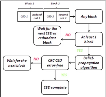
In order to compare the new code with the structure of the GPS L1C, the CED which is stored in the second subframe is encoded by the proposed LD-MDS code. Moreover, we avoid the use of the interleaver, since it is the main cause of an almost constant ""# in the GPS L1C structure. Regarding the decoding step, once k = 2 blocks of information are retrieved, the erasure algorithm is used to retrieve the systematic information. In order to check the reliability of the systematic data the CRC algorithm is executed. In case of non-free error solution, the BP error correcting solution is executed once more that k = 2 information blocks are retrieved. The decoding scheme is described in figure 4.
Figure 4 LD-MDS & MDS Decoding Schemes
Maximum Distance Separable (MDS) Codes Scheme
Lowest-Density MDS codes provide a solution where the complexity of the decoding algorithm is as low as possible. However, such as codes are not close to the outage boundary under the BP decoding algorithm. The next family of codes looks for increase the error correcting capabilities (with regard to the LD-MDS) by reducing the sparsity of the parity check matrix.
In order to find MDS Codes, we can think about modifying the parity check matrix of equation (5) and introducing the following parity check matrix:
^_ = `aB u aB a:u a: ab u ab …… ac u ac 0I 0Id (8)
In order to generate a channel coding scheme, with rate ½ and code structure C(u,m) with u = 600 and m = 1200, we define the following matrix:
^_= `aBu aB
a:u
a: 0 Id I 0 (9)
where a = {aB, a:, aBu, a:u} of size s + s where s = 300. As it happened with the LD-MDS code structure, CED and redundant data are divided in four blocks.
One remarkable fact is the new proposed MDS codes schemes are incompatible with the low complexity erasure decoding algorithms developed for the LD-MDS codes. In order to retrieve the systematic information for the new codes a new erasure decoding algorithm is proposed.
MDS erasure decoding algorithm:
Let’s define the received word as v) with ' ∈ (1,2,3,4) and size 1 + s the transmitted word w) and the error word as x) such as v)= w)+ x) . Let’s calculate the syndromes as:
y<= aBuvB+ a:uv:+ vb (10)
yB= aBvB+ a:v:+ vz (11)
Let’s define the erasure blocks as 1 ≤ | < V ≤ 4. It is clear that if V = 4 and:
- | = 3 the information has been already retrieved. - | = 2 → y<= a:ux: and x:= (a:u)€By<
- | = 1 → y<= aBuxB and xB= (aBu)€By< if V = 3 and:
- | = 2 → yB= a:x: and x:= (a:)€By< - | = 1 → yB= aBxB and xB= (aB)€By< if V = 2 and | = 1:
- Following equations (11) ,xB= (aBu)€B(y<+ a:ux:)
- Substituting the precedent equation in the equation (12), yB= aB(aBu)€B(y<+ a:ux:) + a:x:. - We obtain x: as x:= (aB(aBu)€Ba:u+ a:)€B( yB+ aB(aBu)€By<).
- We obtain xB by substituting x: in xB= (aBu)€B(y<+ a:ux:).
Of course aB, a:, aBu, a:u and (aB(aBu)€Ba:u+ a:) must be invertible over XY(2).
In order to construct the MDS code defined by (9), the set of matrix a = {aB, a:, aBu, a:u} are selected by random regular distribution under the following constraint:
- aB, a:, aBu, a:u and (aB(aBu)€Ba:u+ a:) must be invertible over XY(2).
As is was already described for the LD-MDS codes, once k = 2 blocks of information are retrieved, the erasure algorithm is used to retrieve the systematic information. In order to check the reliability of the systematic data the CRC algorithm is executed. In case of non-free error solution, the BP error correcting solution is executed once more that k = 2 information blocks are retrieved. The decoding scheme is described in figure 4.
Root-LDPC Codes Scheme
Root-LDPC codes are the last error correcting scheme proposal. These codes are characterized for being MDS and full diversity under iterative BP decoding. This means that the erasure decoding algorithm is not developed since the BP decoding algorithm is capable of retrieving the information after k free error information blocks are received. The generation of Root-LDPC codes is based on the graph theory, which is then translated in matrix representation. It must be underlined that Root-LDPC codes have been widely used to struggle the block fading channel.
The design of the Root-LDPC codes is referring to one limiting case where the fading coefficient can belong to set ℵ ∈ {0, 1}, which corresponds with the well-known block erasure channel. In such as approach, we need to find a graph topology yields
full diversity. In order to design the Root-LDPC codes, the single LDPC parity check nodes are not a sufficient condition to tolerate more than one erasure bit as it is shown in [4]. As a consequence, a new check node definition, considered as rootcheck is absolutely necessary to tolerate more than one erasure bit under the BP decoding algorithm. In order to propose a new error correcting scheme, the construction of a regular structure (3,6) under a block fading channel nc = 2 is proposed. Definition 2: Let’s have a checknode connected to bits +B, +:, … , +•. Let +B be a binary element transmitted on fading AB. A rootcheck for +B is a checknode where all bits +:, … , +•are transmitted on fading A:.
Using Definition 2 and considering a length $ (rate-1/2 LDPC code), the systematic information bits are split into two classes: $/4 bits (i1), which are transmitted on AB and $/4 bits (i2), which are transmitted on A:. Parity bits are also partitioned into
two sets (p1 and p2). Finally, we connect all information bits to rootchecks in order to guarantee full diversity. This design
produces a bipartite Tanner graph, which for a regular structure (3,6) is drawn in Figure 5.
Figure 5 Tanner Graph for a Regular (3,6) Root-LDPC Code of Rate 1/2
The structure of ^ for a root-LDPC code is directly derived from its Tanner graph. The $/4 + $/4 identity matrix is written twice in connections i1↔ c1 and i2↔ c2. Two all-zero $/4 + $/4 submatrices which forbid any edge of type p1↔ c1 and p2↔
c2. The other 4 submatrices are sparse regular matrix: ^)B and^): matrices of Hamming weight 2 per row and per column, ^‚B
and ^‚: matrices of Hamming weight 3 per row and per column.
^_= ` I^)B ^‚B0 ^):I ^‚:0 d (13) Examining equation (13), under the block-erasure channel scenario, we observe that the only outage event occurs when AB= A:= 0 (both blocks erased). Indeed, when AB= 0 and A:= 1, it is straightforward to see that information bits i1 are
determined using rootchecks c1. Similarly, when AB= 1 and A:= 0, information bits i2 are determined using rootchecks c2.
In order to generate the parity bits, one requirement must be accomplished by the parity check matrix. Let‘s re-structure the parity check matrix by inserting the systematic information in the first columns as it is illustrated in (14).
^_= ` I^)B ^):I ^‚B0 ^‚:0 d = ( ƒ „ ) (14) The parity check matrix shown in (14) can be divided into two submatrices: A and B. Let’s denote&̅ = [‡ˆ ‰̅] as the codeword generated by the generator matrix, where ‡ˆ is the systematic information bits and ‰̅ is the parity bits. Since ^&̅" = ƒ‡ˆ" + „‰̅" = 0, for binary codes we can obtain the parity bits from (15).
As long as we obtain „€B, the encoding can be accomplished by using (15) with linear complexity as a function of the length of parity bits. However, there is one main concern to obtain „€B:
· „€B may not be invertible.
From the precedent statement, we conclude that B must be full rank in order to have inverse. In order to enhance the code performance we also propose to not have girth-4 loops in H, since as it is shown in [4], a 4-loop under BP decoding reduces the error correcting performances.
Finally, two methods to generate the parity and the generator matrix have been used: · Quasi Cyclic (QC) matrix [5].
· Modify Progressive Edge Growth (PEG) algorithm [6].
Both methods look to construct a regular (3,6) code structure. The decoding scheme is described in figure 6.
Figure 6 Root-LDPC Decoding Schemes
Following Definition 2, it is trivial that the data structure of a regular Root LDPC (3,6) code must be divided into two different blocks, each one corresponding to AB or A:
.
Once one of the blocks is received, the decoding process starts by executing the BP algorithm. In case of retrieving a correct CRC the CED is retrieved, otherwise another block must be received.VI- RESULTS
In order to compare the performances of the error correcting solutions proposed in section V, retrieved CED Error Rate (CEDER) and the ""#are evaluated.
The Additive White Gaussian Noise (AWGN) channel is the model used to estimate the background noise on the transmission channel. This model does not include fading or interferences coming from other sources. The model follows (15) [8]:
(c= +c+ %c (15)
where (c is the received sample,+c is the transmitted symbol and %c is the AWGN noise. Moreover %c~‹(0, Œ:) where Œ:= $</(4 )) [8] and )= 4ms.
Time To Data (•••Ž)
The following analysis considers the following assumptions: · Time of Week (TOW) is assumed to be known. · The results are expressed in terms of the ""# values.
In order to obtain the ""#values, we need to define the Probability Density Function (PDF) of the ""#. The ""# can then be obtained from the Cumulative Distribution Function (CDF) defined in (16).
w•Y( ""#) = •"’’“E•Y(‘)L‘
€P = +
(16)
where x describes the percentage of confidence needed in order to represent the time needed by the receiver to retrieve CED. For simulations, we evaluate 100.000 times the duration needed by one receiver to obtain the error free CED for each of the proposed error correcting solutions under C/N0 = 25 dBHz, C/N0 = 35 dBHz and C/N0 = 45 dBHz. As expected, the first epoch
(first synchronized bit) can arrive at any time. Following the structure of GPS L1C message, each subframe represents 1800 bits, therefore in order to initialize the first epoch value for each of the 100.000 simulations, an uniform distribution with values between 1 and 1800 is used. Each of the values represents a possible first synchronized bit.
The three error correcting schemes along with a new message structure are simulated and compared with the GPS L1C CED error correcting scheme and between themselves under the AWGN channel assumption. In order to evaluate the reduction of ""#, an analysis of the time to retrieve the CED based on the calculation of the cumulative distribution function (CDF) is implemented. Simulation results are presented in figure 7, figure 8 and figure 9.
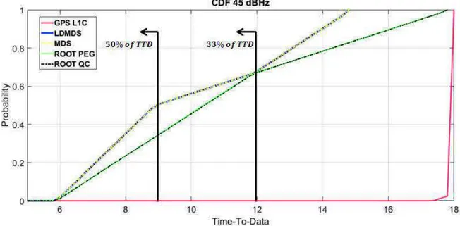
Figure 7 CDF of the Error Correcting Candidates C/N0= 45 dBHz
Simulation results in figure 7 show a reduction of more than 30% of TTD for at least 66 % of the time compared with the current GPS L1C signal and a reduction of 50 % of TTD for at least 33 % of the time in case of Root-LDPC scheme (under high C/N0 = 45 dBHz channel conditions). Those results are even better in case of LD-MDS and MDS schemes, where
simulation shows a reduction of 50% of ""# for at least 50 % of the time compared to the current GPS L1C signal. The main reason of the improvement of the ""# performance is due to the MDS property. Thanks to that property, under good channel condition, the proposed error correcting schemes are capable to reduce the time to retrieve the CED since not all the information (redundant or systematic) are need in order to compute the solution. Moreover, the MDS and LD-MDS schemes provide better results in terms of ""# compared to the Root codes due to the MDS property which works in any of the 4 blocks of the message structure. Since the message structure of the Root codes requires dividing the redundant and systematic information in a maximum of 2 blocks, the MDS property over Root codes has not as many degree of freedom as in MDS and LD-MDS codes.
Figure 8 CDF of the Error Correcting Candidates C/N0 = 30 dBHz
Simulation results in figure 8 show the CDF of the error correcting candidate for a C/N0 = 30 dBHz. A reduction of the ""#
for at least 66 % of the time compared with the current GPS L1C signal is shown for the case of Root codes and an reduction of ""# for at least 90 % of the time in case of the LD-MDS scheme. Under this channel conditions it is shown that the MDS candidate provides a better solution for 100% of the case. It must be remarked that the LD-MDS solution provides a worse solution than the MDS since the error correcting capabilities of the MDS codes are higher than the error correcting capabilities of the LD-MDS.
Figure 9 CDF of the Error Correcting Candidates C/N0 = 25 dBHz
Simulation results in figure 9 show the CDF of the error correcting candidate for a C/N0 = 25 dBHz, which can be considered
as low AWGN C/N0 conditions. A reduction in the ""#, for almost 20% of the cases, is shown for Root codes, compared with
the current GPS L1C signal. Otherwise, same performance as the GPS L1C is accomplished. We remark that Root codes are capable of achieving as good performance as the GPS L1C under low C/N0conditions thanks to the full diversity property
under the BP algorithm which provides notable error correcting capabilities. Under the MDS codes scheme, a reduction in the ""# is accomplished (for at least 60% of the cases) thanks to the MDS property. By the other hand there is an increment in the ""# in the remaining of the cases (yellow line cross the red line at the 60 %), since such as code are not full diversity under the BP algorithm and a reduction in the error correcting capabilities are contemplated. It should be remarked that the LD-MDS
solution is not presented in the figure 9; that is because the LD-MDS codes do not converge for low AWGN C/N0 conditions
due to poor error correcting capabilities.
We conclude that codes characterized by the full diversity and with the MDS property can reduce the T••– under good channels conditions without increasing the T••– under low C/N0conditions.
Retrieved CED Error Probability
For our performance evaluation, we assume that the entire subframe 2 has been retrieved, in other words 600 bits of systematic information and 600 redundant bits.
Figure 10 illustrates the CED error probability in terms of C/N0 for GPS L1C, LD-MDS, MDS, LDPC QC and
Root-LDPC PEG codes.
Figure 10 Retrieved CED Error Probability
In order to evaluate the error correcting algorithms capabilities, CEDER, which is equivalent to the evaluation of the probability of retrieving the CED under one specific C/N0 value, is calculated under the AWGN channel assumption.
Simulation results show that regular Root-LDPC codes obtain the best demodulation threshold compared with LD-MDS and MDS codes (demodulation threshold gain of 6 dBHz and 0.9 dBHz respectively for a targeted error probability of 10€:). Moreover, simulation shows that a small difference in the error correcting performance between the Root–LDPC and the current GPS L1C (0.4 dBHz) along with the MDS property, can provide a channel coding scheme, which accomplishes a reduction in the ""# under high or low C/N0 conditions without degrading the demodulation threshold. Moreover error
correcting performance between Root-Codes and the GPS L1C channel coding scheme can be minimized or nulled out by designing irregular Root-LDPC codes (future work).
It should be remarked that Root–LDPC codes were first designed in order to encounter fading environments as the Land Mobile Satellite (LMS) channel case, thus they can be considered as a new possible solution in order to avoid interleaving structures, which increment the ""# and finally the TTFF.
Note that Root codes obtain lower performance on the AWGN because they are regular LDPC codes. Under irregular Root codes design, an improvement in the error correcting performance can be achieved.
VII- CONCLUSION
To sum up, three message structure and channel coding co-design schemas are proposed in order to reduce the ""# and to provide enhanced error correction capabilities under C/N0 environments. In order to design such as schemes, MDS and full
diversity properties are required under the non-ergodic (erasure) channel assumption. Simulation results show MDS codes provide a remarkable solution in order to reduce the ""# under good channel conditions thanks to the MDS property. By the other hand, Root–LDPC provides a good solution in order to reduce the ""# without degrading the error correction
performances under low C/N0 environments. Such results are achieved thanks to combine the MDS and full diversity
properties, which are natural properties of the Root–LDPC codes under the BP decoding algorithm.
VIII- ANNEX A
Here the low complexity erasure algorithm [3], used by the LD-MDS code scheme to retrieve the systematic information once V error free information units have been supplied, is presented.
From the parity check matrix defined in (7), the syndrome values of the received messages (v—)—˜BcO: over XY(2‚€B) are defined by:
y<= vB+ v:+ ⋯ + vc+ vcOB (17) yB= „BvB+ „:v:+ ⋯ + „cvBc+ vcO: (18) Now assume that the received words (v—)—˜BcO: have been erased at the entries ' and |, 1 ≤ ' < | ≤ V + 2. As v) and v™ are erased, we initially set v™= v)= 0. We have three possible options:
· It is clear that if | = V + 2, the error x)= y<
· if | = V + 1, the error y<= x)+ xcOB and yB= „)x); so, x)= „)€ByB and xcOB= y<− „)€ByB · if 1 ≤ ' < | ≤ V then y<= x)+ x™ and yB= „)x)+ „™x™ thus yielding:
o x™= š„™− „)›€B(yB− „)y<) and x)= y<− x™ From the identities above we develop the next algorithm [3]:
· Setv™= v)= 0
· If | = V + 1 → vcOB= −(y<− „)€ByB)
· Else if 1 ≤ | ≤ V → v™= −š„™− „)›€B(yB− „)y<) Let v)= −(y<+ v™) and output (v—)—˜Bc
ACKNOWLEDGMENTS
This work is funded by the French Space Agency, CNES, and Thales Alenia Space. REFERENCES
[1] Birgit E. Schotsch, Marco Anghileri, Thomas Burger, Mahamoudou Ouedraogo, “Joint Time-to-CED Reduction and Improvement of CED Robustness in the Galileo I/NAV Message”. "Proceedings of the 30th International Technical Meeting of The Satellite Division of the Institute of Navigation (ION GNSS+ 2017), Portland, Oregon, September 2017.
[2] E. Biglieri J. Proakis S. Shamai "Fading channels: Information-theoretic and communication aspects" IEEE Trans. Inf. Theory vol. 44 pp. 2619-2692 October 1998.
[3] BLAUM, M., AND ROTH, R. M. “On lowest density MDS codes”. IEEE Transactions on Information Theory 45, 1 (January 1999), 46-59.
[4] J. Boutros A. Guillen i Fabregas E. Biglieri G. Zemor "Low-density parity-check codes for Nonergodic Block-Fading Channels” IEEE Trans. Inf. Theory vol. 56 no. 9 pp. 4286-4300 Sep. 2010.
[5] Y. Li and M. Salehi "Quasi-cyclic LDPC code design for block-fading channels " in Information Sciences and Systems (CISS) 2010 44th Annual Conference on pp. 1-5 Mar 2010.
[6] A. G. D. Uchoa C. Healy R. C. de Lamare and R. D. Souza "Design of LDPC Codes Based on Progressive Edge Growth Techniques for Block Fading Channels "IEEE COMMUNICATIONS LETTERS VOL. 15 NO. 11 pp. 1221-1223 Nov. 2011
[7] Espluga, Lorenzo Ortega, Poulliat, Charly, Boucheret, Marie-Laure, Aubault, Marion, bitar, Hanaa Al, "New Solutions to Reduce the Time-To-CED and to Improve the CED Robustness of the Galileo I/NAV Message," Proceedings of IEEE/ION PLANS 2018, Monterey, CA, April 2018, pp. 1399-1408.
[8] Marion Roudier. “Analysis and Improvement of GNSS Navigation Message Demodulation Performance in Urban Environments”. PhD Manuscript, 2015.