HAL Id: tel-01753394
https://pastel.archives-ouvertes.fr/tel-01753394
Submitted on 29 Mar 2018HAL is a multi-disciplinary open access archive for the deposit and dissemination of sci-entific research documents, whether they are pub-lished or not. The documents may come from teaching and research institutions in France or abroad, or from public or private research centers.
L’archive ouverte pluridisciplinaire HAL, est destinée au dépôt et à la diffusion de documents scientifiques de niveau recherche, publiés ou non, émanant des établissements d’enseignement et de recherche français ou étrangers, des laboratoires publics ou privés.
To cite this version:
Maria Niznik. Improvement and integration of the in-situ heat pump performance assessment method. Fluids mechanics [physics.class-ph]. Université Paris sciences et lettres, 2017. English. �NNT : 2017PSLEM029�. �tel-01753394�
THÈSE DE DOCTORAT
de l’Université de recherche Paris Sciences et Lettres
PSL Research University
Préparée à MINES ParisTech
Ecole doctorale
n°
432SMI - SCIENCES DES MÉTIERS DE L’INGÉNIEUR
Spécialité
ÉNERGÉTIQUE ET PROCÉDÉS
Improvement and integration of the in-situ heat pump performance
assessment method
Amélioration et intégration d’une méthode d’affichage des
perfor-mances en temps réel d’une pompe à chaleur
Dirigée par Dominique MARCHIO
h COMPOSITION DU JURY : M. Eckhard GROLL Purdue University, Rapporteur M. Jocelyn BONJOUR INSA de Lyon, Rapporteur M. Vincent LEMORT University of Liège,
Examinateur, Président du jury
M. Dominique MARCHIO PSL Mines ParisTech, Examinateur M. Philippe RIVIERE PSL Mines ParisTech, Examinateur
Mme. Odile CAURET
EDF R&D, Examinateur
Soutenue par
Maria
NIZNIK
le 10 juillet 2017
hiii
ACKNOWLEDGEMENTS
This PhD was done as a partnership between PSL Mines ParisTech, Centre for Energy efficiency of Systems, and EDF R&D, Energy in Buildings and Territories Depart-ment.
I would like to thank my academic supervisors and mentors, Professor Dominique Marchio and Associate Professor Philippe Rivière, for sharing their abundant knowledge in the heat transfer domain, for their dedication, guidance, valuable feed-back, and advice.
I would like to express my overwhelming gratitude to my supervisor in EDF R&D, Cedric Teuillières. His extensive experience and vast knowledge on the topic helped me greatly throughout these three years. And most importantly, it is his irreplaceable support and encouragement that gave me strength and endurance to pursue my goals. These acknowledgements would not be complete without mentioning the input of Odile Cauret; her guidance and interest in this PhD. In addition, a big thank you to the team of Climatron laboratory of EDF R&D for their precious help and technical sup-port.
I owe my deepest gratitude to our group leader, Emmanuel Chabut, for his time, de-spite his busy schedule, understanding, and constant encouragement. I am very grate-ful that I had the opportunity to work in such positive work environment.
I wish to thank Professors Eckhard Groll and Jocelyn Bonjour for taking interest in my research and for their willingness to be reviewers of this thesis. Also, I would like to thank Professor Vincent Lemort for agreeing to participate in the jury board. I am honored to have such prominent jury members.
I would also like to thank Mitsubishi Heavy Industries, particularly Yoshiyuki Kimata and Kiyoshi Watanabe, for providing us with valuable experimental data.
I am very grateful to my dear family for your unconditional love, for your support, for your patience, and most importantly for having faith in me. I would not be here without Raphael; without your participation, support, and encouragement
v To my daughter – to my love
vii
NOMENCLATURE
Symbols
A area (m2)
𝐶𝑔 oil mass fraction (-)
𝑐𝑝 specific heat capacity (J kg-1 °C-1)
D diameter (m)
g gravitational acceleration (m s-2) h heat transfer coefficient (W m-2 °C-1)
h specific enthalpy (J kg-1)
k thermal conductivity (W m-1 °C-1)
L length (m)
𝑚̇ mass flow rate (kg s-1)
Nu Nusselt number (-)
P pressure (kPa)
p perimeter (m)
Pr Prandtl (-)
𝑄̇ heating power (W)
𝑅𝐻𝐹 heat flux ratio (-)
Ra Rayleigh number (-)
Re Reynolds number (-)
S sensitivity index (-)
T temperature (°C)
t time (s)
𝑉̇ volume flow rate (m3 s-1)
v velocity (m s-1) 𝑊̇ power consumption (W) X measured variable (-) x characteristic length (m) Y calculated variable (-) 𝛼 thermal diffusivity (m2 s-1)
𝛽 thermal expansion coefficient (K-1)
𝜎 standard deviation (-)
𝜎 Stefan-Boltzmann constant (W m-2 K-4)
ν kinematic viscosity (m2 s-1)
𝜌 density (kg m-3)
viii
Subscripts
amb ambient
atm atmospheric
ca condenser air
cha-cyl compression chamber lateral walls (internal) cha-bot compression chamber bottom plate (internal) cha-top compression chamber top plate (internal)
comp component
comp compressor
comp-cham compression chamber
cond condenser dis discharge e electric ea evaporator air eff effective evap evaporator in inlet is isentropic non-is non-isentropic o oil out outlet r refrigerant ref reference s surface sc subcooling sh superheat suc suction w water Abbreviations AC air conditioner
CFD computational fluid dynamics COP coefficient of performance CO2 carbon dioxide
DHW domestic hot water
EEV electronic expansion valve
ix FDD fault detection and diagnostic
FDM finite difference method FEM finite element method
FT flash tank
FVM finite volume method
FXO fixed orifice expansion valve
GHG greenhouse gas
HP heat pump
HP high pressure
IHX internal heat exchnager
LP low pressure
OC oil concentration
PDE partial differential equation
RMS root-mean-square
R134a refrigerant type R407C refrigerant type TNW thermal network
TXV thermostatic expansion valve
2D two-dimensional
xi
TABLE OF CONTENTS
INTRODUCTION ... 1
CHAPTER 1 BACKGROUND AND LITERATURE REVIEW ... 7
1.1 Overview of heat pumps ... 8
1.2 Performance assessment method using indirect measurement of refrigerant mass flow rate ... 15
1.2.1 Compressor energy balance ... 15
1.2.2 Influence of compressor heat losses ... 19
1.3 Fault detection and diagnostic using mass flow rate measurements ... 21
1.3.1 Main faults in the heat pump unit ... 21
1.3.2 Fault detection and diagnostic method ... 24
1.4 Conclusions ... 26
CHAPTER 2 COMPRESSOR HEAT TRANSFER MODEL ... 29
2.1 State-of-the-art of compressor heat transfer ... 30
2.1.1 Correlations based on experimental measurements ... 30
2.1.2 Numerical models ... 32
2.2 Numerical model of compressor heat transfer ... 35
2.2.1 Modelling approach ... 35
2.2.2 Scroll ... 38
2.2.3 Rotary ... 54
2.3 Conclusions ... 60
CHAPTER 3 EXPERIMENTAL VALIDATION OF THE NUMERICAL MODEL ... 63
3.1 Experimental setup ... 64
3.2 Comparison of thermal profiles ... 66
3.2.1 Scroll ... 67
3.2.2 Rotary ... 72
3.3 Discussion ... 75
3.3.1 Simplifications ... 77
3.3.2 Model applicability to different compressor dimensions and component layouts ... 80
3.4 Future development ... 81
3.5 Conclusions ... 82
CHAPTER 4 IMPROVED IN SITU EVALUATION METHOD OF COMPRESSOR HEAT LOSSES FOR PERFORMANCE ASSESSMENT ... 83
4.1 Introduction ... 84
xii
4.3 Improved calculation method of compressor heat losses ... 86
4.3.1 Nusselt number correlations for convective heat transfer coefficients .... 86
4.3.2 Optimal on-field instrumentation for Tshell ... 88
4.3.3 Heat loss expression for compressors ... 91
4.4 Conclusions ... 92
CHAPTER 5 EXPERIMENTAL VALIDATION OF THE PERFORMANCE ASSESSMENT METHOD ... 93
5.1 Introduction ... 94
5.2 Heat pump prototype ... 94
5.3 Experimental setup ... 96
5.4 Comparison of proposed performance assessment method with reference method ... 102
5.4.1 Reference heating capacities... 103
5.4.2 Additional factors influencing the results of the method... 103
5.4.3 Comparison with other heat loss values ... 104
5.4.4 Operating conditions ... 104
5.5 Uncertainty values analysis ... 105
5.6 Results of on-field performance assessment method ... 107
5.7 Conclusions ... 115
CONCLUSIONS AND PERSPECTIVES ... 119
BIBLIOGRAPHY ... 124
APPENDIX A EXTENSION OF THE PERFORMANCE ASSESSMENT METHOD TO A FDD METHOD ... 130
A.1 Fault detection and diagnostic methods ... 131
A.2 Promising fault detection and diagnostic method ... 132
A.3 Conclusions ... 137
APPENDIX B EXPERIMENTAL TECHNIQUES FOR COMPRESSOR THERMAL ANALYSIS ... 138
APPENDIX C ADDITIONAL NUSSELT NUMBER CORRELATIONS ... 142
C.1 Nusselt number correlation for the stator-rotor gap ... 143
xiii
LIST OF FIGURES
Figure 1.1 Schematic (a) and P-h diagram (b) of a HP refrigeration cycle ... 9 Figure 1.2 Reversible heat pump in heating (a) and cooling (b) mode
(COSTIC, 2004) ... 10 Figure 1.3 Working principle of a scroll compressor (Hitachi Industrial
Equipment Systems, 2017) ... 11 Figure 1.4 Working principle of a rotary compressor (Lee, Shim, & Kim, 2016) ... 12 Figure 1.5 Refrigeration cycle P-h diagram (a) and schematic with required
measurements (b) of basic cycles ... 16 Figure 1.6. Refrigeration cycle P-h diagram (a) and schematic with required
measurements (b) of FT injection cycle ... 18 Figure 1.7. Refrigeration cycle P-h diagram (a) and schematic with required
measurements (b) of IHX injection cycles ... 19 Figure 2.1. Example of heat flux sensors used to measure compressor heat
fluxes in the work of Dutra & Deschamps (2013) ... 31 Figure 2.2. Illustration of a hybrid model approach when modeling heat
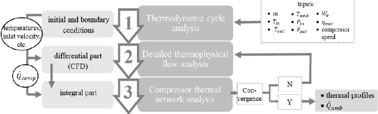
transfer of stator ... 34 Figure 2.3. Schematic of the three calculation steps of the model ... 36 Figure 2.4. Computational domains of scroll (a) and rotary (b) compressors ... 37 Figure 2.5. Thermodynamic refrigeration cycle of a heat pump with associated
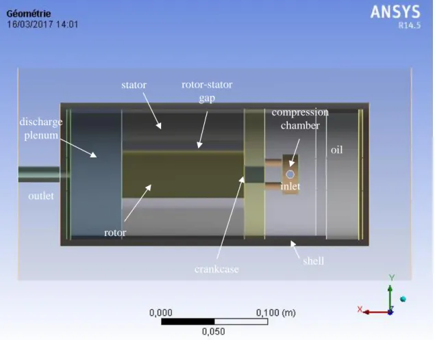
power distributions inside the compressor ... 39 Figure 2.6. Computational domain of scroll compressor in ANSYS Workbench
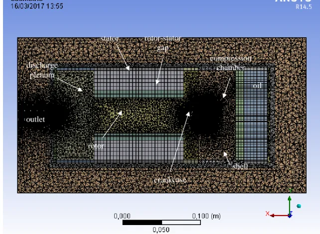
pre-processing tool, Design Modeler ... 43 Figure 2.7. Structured (on the left) and unstructured (on the right) grids ... 44 Figure 2.8. Scroll compressor mesh in ANSYS Workbench pre-processin tool,
Mechanical ... 45 Figure 2.9. Equilateral and highly skewed triangle ... 46 Figure 2.10. Thin layer of oil in solid phase between refrigerant and oil sump
in liquid state... 48 Figure 2.11. Required heat to reach Tdis (temperature of the compressed fluid
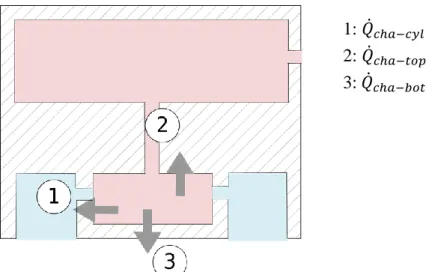
at discharge) ... 48 Figure 2.12. Heat fluxes released from the fluid to compression chamber... 51 Figure 2.13. Flow inside the compression chamber (above) is approximated as
the flow inside a pipe (below) ... 53 Figure 2.14. Computational domian of rotary compressor in ANSYS
Workbench pre-processing tool, Design Modeler ... 56 Figure 2.15. Insulation layer high-lighted in green around the exterior shell of
the compressor ... 57 Figure 2.16. Rotary compressor mesh in ANSYS Workbench pre-processing
xiv
Figure 3.1. Calorimeter chamber of the scroll and rotary compressor test
bench used for experimental validation ... 64 Figure 3.2. Location of thermocouples on compressor shells of scroll (a) and
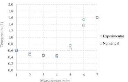
rotary (b) compressors ... 66 Figure 3.3. Experimental and numerical shell temperature distributions in
scroll compressor at Tcond = 40 °C, Tevap = 0 °C, and
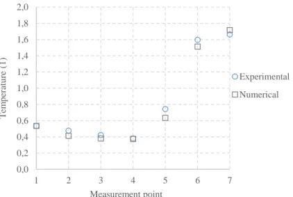
Tamb = 10 °C, 30 rps (operating condition 1) ... 68 Figure 3.4. Experimental and numerical shell temperature distributions in
scroll compressor at Tcond = 40 °C, Tevap = 0 °C, and
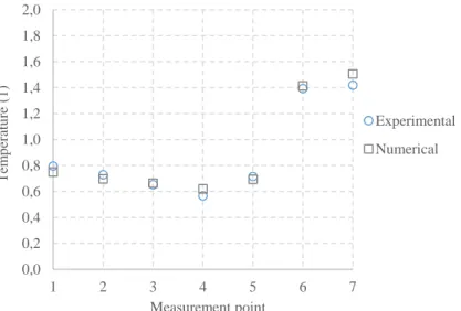
Tamb = 10 °C, 60 rps (operating condition 2) ... 68 Figure 3.5. Experimental and numerical shell temperature distributions in
scroll compressor at Tcond = 60 C, Tevap = 0 C, and Tamb = 10, 30 rps (operating condition 3) ... 69 Figure 3.6. Experimental and numerical shell temperature distributions in
scroll compressor at Tcond = 40 °C, Tevap = 15 °C, and
Tamb = 25 °C, 30 rps (operating condition 4) ... 69 Figure 3.7. Experimental and numerical shell temperature distributions in
scroll compressor at Tcond = 40 °C, Tevap = 15 °C, and
Tamb = 25 °C, 90 rps (operating condition 5) ... 70 Figure 3.8. Experimental and numerical component temperatures in scroll
compressor at Tcond = 40 °C, Tevap = 0 °C, and Tamb =
10 °C, 30 rps (operating condition 1) ... 71 Figure 3.9. Experimental and numerical component temperatures in scroll
compressor at Tcond = 40 °C, Tevap = 15 °C, and Tamb =
25 °C, 30 rps (operating condition 4) ... 71 Figure 3.10. Experimental and numerical component temperatures in scroll
compressor at Tcond = 40 °C, Tevap = 15 °C, and Tamb =
25 °C, 90 rps (operating condition 5) ... 72 Figure 3.11. Experimental and numerical shell temperature distributions in
rotary compressor at Tcond = 40 °C, Tevap = 0 °C, and
Tamb = 10 °C, 30 rps (operating condition 1) ... 73 Figure 3.12. Experimental and numerical shell temperature distributions in
rotary compressor at Tcond = 40 °C, Tevap = 0 °C, and
Tamb = 10 °C, 60 rps (operating condition 2) ... 73 Figure 3.13. Experimental and numerical shell temperature distributions in
rotary compressor at Tcond = 60 °C, Tevap = 0 °C, and
Tamb = 10 °C, 30 rps (operating condition 3) ... 74 Figure 3.14. Experimental and numerical shell temperature distributions in
rotary compressor at Tcond = 40 °C, Tevap = 15 °C, and
xv Figure 3.15. Experimental and numerical shell temperature distribution in
rotary compressor at Tcond = 40 °C, Tevap = 15 °C, and
Tamb = 25 °C, 90 rps (operating condition 5) ... 75
Figure 3.16. Temperature contours of rotary compressor shell in absolute temperature (K) ... 76
Figure 3.17. Temperature contours of scroll compressor shell in absolute temperature (K) ... 77
Figure 3.18. Thin oil film forming an interface betwee the refirgerant gas and a solid component ... 78
Figure 3.19. Different inlet locations in scroll compressor and their effect on the refrigerant flow paths... 80
Figure 4.1. Location of temperature sensors required to evaluate heat losses of rotary (on the left) and scroll (on the right) compressors ... 91
Figure 5.1. Exterior unit with a compressor and EEV separated by a metallic sheet from the evaporator and fan ... 95
Figure 5.2. Exterior unit from the side of the evaporator ... 95
Figure 5.3 Exterior unit from the side of the fan ... 96
Figure 5.4. Exterior unit located in the climatic chamber 2 (outdoor chamber) ... 97
Figure 5.5. Indoor unit with condenser coupled to a water loop (on the left) and contorl unit of water inlet temperature located in room number 3 (on the right) ... 97
Figure 5.6. Air-to-water HP prototype and required instrumentation installed in three climatic chambers ... 98
Figure 5.7. Locations of sensors used to measure the temperature of air surrounding the compressor ... 100
Figure 5.8. Thermometer (PT100) used to measure the evaporator inlet air, i.e. Text ... 101
Figure 5.9. Refrigeration cycle P-h diagram (a) and a schematic with required measurements (b) for the experimental validation of the performance assessment method ... 102
Figure 5.10. Root mean square errors of the estimated heating capacities when Qamb is obtained using different air temperature sensors ... 107
Figure 5.11. Deviations of heating capacities from reference values when Qamb is obtained using different air temperature sensors ... 108
Figure 5.12. Deviations of heating capacities calculated using the previosuly defined Qamb evaluation method and the more accurate method from the reference values as a function of compressor speeds ... 109
Figure 5.13. Comparison of heating capacities deviations from the reference values with different Cg values... 110
Figure 5.14. Required instrumentation to measure rotary compressor heat losses on-field... 111
xvi
Figure 5.15. Reference and calculated heating capacities at different operating conditions ... 111 Figure 5.16. Compressor heat losses calculated from the new heat loss
evaluation method, Eq. (5.1), old heat loss evaluation method, Eq. (1.19) and reference values Eq. (5.8) in tested operating
conditions ... 112 Figure 5.17. Deviations in heating capacities from reference values as a
function of compressor speed... 113 Figure 5.18. Deviations in heating capacities from reference values as a
function of compressor power input ... 114 Figure 5.19. Deviations in heating capacities from reference values as a
function of evaporation temperature ... 114 Figure 5.20. Deviations in heating capacities from reference values as a
function of temperature difference between compressor shell
and ambient temperatures... 115 Figure A.1. Flow chart diagram of condenser fouling detection algorithm ... 134 Figure A.2. Flow chart diagram of evaporator fouling detection algorithm ... 135
xvii
LIST OF TABLES
Table 1.1 Most common faults occurring in the HP unit ... 23
Table 3.1 Operating conditions used to obtain experimental results for numerical model validation ... 67
Table 3.2 Dimensionless RMS errors of external profiles in different operating conditions in scroll compressor ... 70
Table 3.3 Dimensionless RMS errors of external profiles in different operating conditions in rotary compressor ... 75
Table 4.1. The RMS errors of temperature values measured from different temperature sensors from the area-weighted average temperatures of the rotary compressor shell ... 85
Table 4.2. Shell heat flux ratio of scroll compressor extracted from Fluent in different operating conditions ... 89
Table 5.1. Location of ambient temperature sensors ... 100
Table 5.2. Operating conditions tested in the experimental test bench ... 105
Table 5.3. Sensors used in measurements and their respective uncertainties ... 105
Table 5.4 Sensitivity index of each variable in the final uncertainty of the calculated heating power in operating condition 6 ... 113
Table 5.5. Optimal instrumentation used to determine Tshell in scroll and rotary compressors ... 117
Table A.1. Fault decoupling features, required temperature measurements, and virtual measurements ... 137
Table B.2 Measurement techniques used to determine compressor thermal behavior ... 140
INTRODUCTION
Le développement des pompes à chaleur (PAC), qui offrent des efficacités énergé-tiques élevées, est essentiel pour réduire la consommation d’énergie dans les bâtiments et répondre aux enjeux énergétiques et environnementaux à l’échelle nationale ou eu-ropéenne. Cependant, les performances réelles des PAC sont difficiles à évaluer sur site. Une méthode adaptée par Tran et al. (2013) permet de mesurer leurs performances sur le terrain mais sa précision reste fortement dépendante de l’évaluation des pertes thermiques du compresseur.
L’objectif de cette thèse est d’améliorer cette méthode de mesure en identifiant et va-lidant une approche simplifiée d’évaluation sur site des pertes thermiques du compres-seur.
La méthode de mesure des performances est détaillée dans le chapitre 1. Deux modèles numériques de comportement thermique de compresseurs (scroll et rotary) sont expo-sés dans le chapitre 2. Après leur validation expérimentale (chapitre 3), les modèles sont utilisés dans le chapitre 4 pour déterminer l’approche à adopter pour pouvoir éva-luer précisément les pertes thermiques sur site. Cette approche est ensuite intégrée dans la méthode de mesure des performances réelles et validée en laboratoire sur un proto-type de pompe à chaleur air-eau dans le chapitre 5.
2
Research objective
The three key targets for 2020 of the European Union (EU) climate action is to reduce greenhouse gas (GHG) emissions by 20% when compared with emission levels in 1990, ensure that 20% of total energy consumption is from renewable energy, and a 20% increase in energy efficiency (European Commission, 2017). It has been shown that a major part of the GHG emissions originate from heating and domestic hot water (DHW) consumption. According to French Environment and Energy Management Agency (2014), heating and DHW production was responsible for 25% of total CO2
emissions and 40% of final energy consumption in France. For these reasons, efficient and environmentally friendly energy solutions for heating and DHW production are in demand. One of these solutions consists of using residential heat pumps (HPs). Due to high theoretical efficiency of residential HPs, their development is essential when attempting to reduce heating energy consumption in dwellings. However, cur-rent methods to evaluate HP efficiencies have become problematic since efficiencies are measured and established in controlled laboratory conditions (Ertesvåg, 2011). Performance values obtained in such conditions may differ from the ones obtained on-field due to several factors, such as installation quality, design of the heating system, and climatic conditions. Therefore, real-time on-field performance measurements pro-vide more reliable data. Nevertheless, measuring accurately on-field heating capacity and coefficient of performance (COP) of HPs is difficult, particularly, of air-to-air HPs, since measuring air enthalpies and specifically air mass flow rate on-field is chal-lenging (McWilliams, 2002).
A performance assessment method, presented and validated in the work of (Tran et al., 2013) demonstrates that air-to-air HP efficiencies can be measured using mass/energy balances of the refrigeration components. The measurements necessary for this method, located on the refrigerant side, require only non-intrusive supplementary sen-sors, surface temperature sensen-sors, in addition to already installed pressure sensors. The method is, therefore, well-adapted for in-situ performance evaluation.
Performance assessment method is based on compressor energy balance, where com-pressor heat losses towards the ambient air must be estimated. Tran et al. (2013) stated that the sensitivity index of heat losses in the relative uncertainty of heating capacity predicted by the method is 40 %. Thus, compressor heat losses must be evaluated more accurately as they influence significantly the overall accuracy of the method.
The method consists of measuring indirectly the refrigerant mass flow rate using the compressor energy balance. The heating capacity is then obtained using this value and by measuring condenser inlet and outlet enthalpies. Finally, the COP value of HP can then be calculated directly as a ratio of heating capacity to the measured HP electrical
Introduction
3 power input. An advantage of this on-field performance measurement is to ensure op-timal operation of HP systems by promptly detecting significant performance degra-dation. This diagnosis reflects positively on energy and cost savings. Additionally, re-frigerant mass flow rate also provides in itself valuable information in terms of fault detection and diagnostics (FDD). Therefore, integrating an on-field FDD technology is important to minimize performance degradation, maintenance costs, such as field inspections and component replacements, and machine down-time. To sum up, the method provides means for the optimization of HP operation and maintenance quality. The aim of this thesis is to improve the method presented by Tran et al. (2013) by investigating the simplest way to measure precisely compressor heat losses on-field, and then to experimentally validate this fully operational and reliable in-situ assess-ment method of HP performances. The newly proposed method should be compatible withvarious refrigeration cycles, such as air-to-air HPs, with and without vapor injec-tion, and easily applicable in already-installed machines.
Research objectives stated above are achieved in three steps:
First, a more accurate method to evaluate compressor heat losses on-field will be established in order to minimize the influence of compressor heat losses on the uncertainty of the performance assessment method. For this purpose, a nu-merical model that simulates compressor thermal behavior is developed. The model couples integral and differential formulations. Exterior thermal profiles of scroll and rotary compressor shells are validated with experimental data ob-tained for both compressor types in Mitsubishi Heavy Industries (MHI) labor-atory.
The simulation model is then used to observe the thermal behavior of compres-sor shells and to determine the minimum non-intrusive instrumentation, i.e. the minimal number of surface temperature sensors and their locations on the ro-tary and scroll compressor shells, necessary to estimate compressor heat losses on-field. Also, the required correlations in order to evaluate convective heat transfer coefficients used to calculate compressor heat losses on-field are se-lected. The methodology to measure scroll and rotary compressor heat losses on-field is established and integrated in the performance assessment method.
The improved method is then experimentally validated in EDF R&D Lab Re-nardières, France, using an air-to-water HP prototype in several operating con-ditions.
4
Thesis overview
Chapter 1 first presents a brief overview of the thermodynamic cycle that constitutes
a HP system: compression, condensation, expansion, and evaporation. In this chapter, state-of-the-art performance measurement methods are presented and their limitations are highlighted.
Chapter 1 also introduces a promising performance measurement method that uses indirect mass flow rate measurement, presented in the work of Tran et al. (2013),and the influence of the current compressor heat loss evaluation integrated in the method on the overall result uncertainty. Finally, a FDD method that can potentially be inte-grated in the proposed performance assessment method is presented.
Chapter 2 illustrates the developed numerical model that simulates heat transfer of
scroll and rotary compressors. Two distinct numerical models have been developed for both compressor types due to differences in the internal component layouts, spe-cifically the location of the electrical motor. The model is a hybrid model where a computational fluid dynamics (CFD) analysis is supported and optimized by integral formulations programmed in MATLAB. Simulations are done in steady state condi-tions. The limitations of the numerical models and suggestions for future development conclude Chapter 2.
Consequently, Chapter 3 deals with the experimental validation of the developed model using measurement results obtained for both compressor types, scroll and ro-tary. The experimental test bench for both compressor types is presented. Introduced simplifications, applicability of the model to different internal component layouts and dimensions, and suggestions for future development are discussed. The chapter con-cludes that the accuracy of the model is sufficient for it to be used to determine the temperature sensor location for measuring on-field compressor heat losses.
Chapter 4 presents the required instrumentation, in terms of temperature sensor
loca-tions for scroll and rotary compressors, and the selected heat transfer correlaloca-tions that can be employed when the shell temperature and the temperature of air surrounding the compressor are known. Thus, Chapter 4 establishes the improved on-field heat loss evaluation method for scroll and rotary compressors.
The performance assessment method with improved heat loss evaluation method is experimentally validated in Chapter 5 with a specific HP test bench. The air-to-water HP prototype built specifically for the HP test bench along with the experimental test set up is presented. The deviations between the heating capacities obtained from the performance assessment method and reference values are presented and discussed.
Introduction
5 Finally, conclusions are drawn on the reliability and applicability of the method in on-field conditions. The possibilities to further exploit the numerical model in order to characterize scroll and rotary compressors of different sizes and to adapt the heat loss evaluation methods accordingly, are explored. It is also proposed to validate the per-formance assessment method coupled with the chosen FDD method with the experi-mental test bench presented in Chapter 5.
6
CHAPTER 1
BACKGROUND AND LITERATURE REVIEW
Pour optimiser la consommation énergétique des PAC, l’évaluation de la puissance thermique et du coefficient de performance sur site en temps réel est importante. Néan-moins, déterminer les performances des PAC reste problématique, notamment dans le cas de PAC air-air, car l’estimation de l’enthalpie et du débit massique de l’air est difficile. Tran et al. (2013) a adapté une méthode qui est basée sur les mesures des propriétés de fluide frigorigène et les bilans énergétique/massique afin d’obtenir les performances d’une PAC en temps réel sur site. Cette méthode utilise seulement des capteurs non-intrusifs. Elle est compatible avec différents types de PAC, y compris les PAC air-air, et est adaptée aux cycles plus complexes (cycles à injection).
La méthode intègre l’évaluation de pertes thermiques du compresseur. Tran et al. (2013) a déterminé que l’incertitude sur l’évaluation de ces pertes contribue à hauteur de 40% sur l’erreur d’estimation de la puissance thermique. Cela illustre l’importance de développer une approche plus aboutie et plus fiable pour évaluer les pertes ther-miques sur site, afin de réduire l’incertitude sur la méthode de mesures des perfor-mances. L’approche utilisée à l’origine dans cette méthode reposait sur l’approxima-tion que la température de l’enveloppe du compresseur est homogène et égale à la température du réfrigérant au refoulement. Toutefois, ceci n’est pas toujours le cas, en particulier pour les compresseurs scroll où la chambre de compression est en haut. La méthode de mesures des performances calcule le débit massique. La connaissance du débit en temps réel est utile dans le modèle de détection et de diagnostic de défauts, présentée dans le travail de Li & Braun (2007). Prochainement, les défauts les plus communs dans les PAC pourraient être testés afin de valider expérimentalement la méthode de détection et de diagnostic de défauts couplée avec la méthode de mesure des performances.
8
1.1 Overview of heat pumps
Following widespread concern with greenhouse gas emissions, climate change, and increasing energy demand in heating and air-conditioning, the development of resi-dential HPs has been a driving force for diminishing heating energy consumption of dwellings, due to their high theoretical efficiency. Currently, millions of HPs are in-stalled worldwide.
Heat pumps constitute heating units or systems that extract heat from outdoor air, which is then used to heat a building. Vapor-compression refrigeration cycle is the basis of the heat transfer cycle, where a chemical substance, the refrigerant, alternately changes phase from liquid to gas and gas to liquid, as depicted in Figure 1.1. The heat transfer cycle consists of four distinct steps:
1. Compression (1-2):
Refrigerant gas entering at low pressure (LP) and temperature is compressed to a higher pressure (HP), thus elevating the temperature, by consuming electrical power input. In some cases injection of refrigerant fluid at intermediate pressure is installed (see Subsection 1.2.1).
2. Condensation (2-3):
Refrigerant gas at high temperature and pressure releases thermal energy to a medium, such as water or air that serves as a heat sink, undergoing phase change from gas to liquid state.
3. Expansion (3-4):
High-pressure and medium-temperature refrigerant liquid is submitted to an expansion by flowing through an orifice in the expansion valve, thus, reducing liquid pressure and temperature.
4. Evaporation (4-1):
Refrigerant at low temperature and pressure absorbs heat from a medium, such air or water that serve as a heat source, undergoing phase change. Finally, low-temperature and low-pressure refrigerant gas flows to the compressor and the cycle is repeated.
1.1 Overview of heat pumps
9 Figure 1.1 Schematic (a) and P-h diagram (b) of a HP refrigeration cycle Reversible heat pumps can reverse the direction of the refrigerant flow between the two heat exchangers, condenser and evaporator, using a reversing valve, as illustrated in Figure 1.2. In such case, the heat pump will operate in a cooling mode, extracting heat from a building and rejecting it to the outdoor air.
Reversible heat pump systems consist of four primary components:
compressor;
condenser;
expansion valve and
evaporator.
10
Figure 1.2 Reversible heat pump in heating (a) and cooling (b) mode (COSTIC, 2004) HEATING Exterior (evaporator) Reversing valve Interior (condenser) Compressor Expansion valve Check valve Reversing valve Exterior (condenser) COOLING Interior (evaporator) Compressor Expansion valve Check valve (a) (b)
1.1 Overview of heat pumps
11
Compressor – The refrigerant entering in a gaseous phase is compressed to a higher
pressure. In the process, the refrigerant temperature is also increased. Heat pump com-pressors require electrical power input. Lubricant oil is used to prevent damage of in-ternal compressor components. In hermetic compressors, the motor and compression chamber are confined in a steel shell. In such compressor types, oil is present in a sump (reservoir) at the bottom of the compressor, and covers the majority of internal com-ponents. Droplets of oil are mixed with refrigerant and part of the oil migrates into the refrigeration cycle. For this reason, the working fluid of a HP cycle is a mix of refrig-erant and lubricant oil.
Scroll and rotary compressors are the two most commonly employed compressor types in residential air-to-air HPs (Tran, 2012). Both compressors are positive displacement compressor types. Scroll compressors have one scroll, or spiral, orbiting in a path that is defined by a matching fixed scroll, creating gas pockets between the scrolls. The orbiting scroll is attached to the crankshaft and the fixed one is attached to the com-pressor body. The gas is drawn in from the outer side portion of the scroll, creating a gas pocket that travels in between the scrolls. The gas then moves towards the center of the scrolls (discharge) simultaneously decreasing the pocket size, increasing the pressure and temperature. The working principle of scroll compressors is illustrated in Figure 1.3.
Figure 1.3 Working principle of a scroll compressor (Hitachi Industrial Equipment Systems, 2017)
In rotary compressors the rotating shaft sets in rotating motion a roller, named the rotor, inside a cavity. The circular rotor rotates inside a circular cavity eccentrically,
12
since the centers of the circular cavity and rotor are offset. This compresses the refrig-erant gas to a desired pressure, as the volume of the gas decreases. The working prin-ciple of a rotary compressor is depicted in Figure 1.4.
Condenser – The heat exchanger condenses refrigerant fluid from gaseous to liquid
state, and delivers extracted heat from the heat source (outdoor air) to the heat sink (indoor air). Typically, a condenser consists of copper coils with aluminum fins. A fan is used to pull the ambient air through the finned coils, creating indoor air circulation across the exchanger. At the same time, the refrigerant circulates inside the finned coils.
Expansion valve – The aim of the expansion valve is to decrease the refrigerant
pres-sure. Thermostatic (TXV) or electronic expansion valves (EEV) are, typically, used to adjust the device opening to ensure a certain pressure drop. Generally, the fluid is in a two-phase state when exiting the expansion valve.
Evaporator – Similar to a condenser, an evaporator, typically, consists of copper coils
with aluminum fins. The refrigerant in a two-phase state in an evaporator is converted to a gaseous state by extracting thermal energy from a heat source (outdoor air). Gen-erally, the refrigerant exiting the evaporator must be in a completely gaseous state, since liquid droplets can damage the compressor. As in the case of condensers, the air crossing the exchanger coils can also be regulated with a fan.
1.1 Overview of heat pumps
13 The First Law of Thermodynamics postulates the conservation of energy stating that energy cannot be created or destroyed, but can be transformed. Assuming that work and heat are the only forms of energy exchanged between the system and surroundings, the First Law is described in:
𝑚̇∆ℎ = 𝑄̇ + 𝑊̇ (1.1)
The equation above is an energy balance for open systems formulated as an enthalpy balance.
Coefficient of performance (COPHP) is the most common indicator of heat pump
effi-ciency. Coefficient of performance is a dimensionless value defined as a ratio of the net heating capacity, 𝑄̇𝑐𝑜𝑛𝑑, and electrical power input, 𝑊̇𝐻𝑃, under designated oper-ating conditions, as listed below:
𝐶𝑂𝑃𝐻𝑃 =
𝑄̇𝑐𝑜𝑛𝑑
𝑊̇𝐻𝑃 (1.2)
The condensation heat, 𝑄̇𝑐𝑜𝑛𝑑, is determined from the condenser energy balance in
steady-state, as follows:
𝑄̇𝑐𝑜𝑛𝑑 = 𝑚̇(ℎ𝑐𝑜𝑛𝑑,𝑖𝑛− ℎ𝑐𝑜𝑛𝑑,𝑜𝑢𝑡) (1.3)
where 𝑚̇ is the mass flow rate of the working fluid, ℎ is the working fluid enthalpy, in and out are condenser inlet and outlet sides, respectively.
As mentioned previously, the working fluid of the HP refrigeration cycle is a refriger-ant and oil mixture, and the enthalpy change at the condenser can be calculated as follows:
∆ℎ𝑐𝑜𝑛𝑑,𝑖𝑛→𝑜𝑢𝑡 = (1 − 𝐶𝑔)(ℎ𝑟,𝑐𝑜𝑛𝑑,𝑖𝑛− ℎ𝑟,𝑐𝑜𝑛𝑑,𝑜𝑢𝑡) + 𝐶𝑔∆ℎ𝑜𝑇𝑐𝑜𝑛𝑑,𝑜𝑢𝑡−𝑇𝑐𝑜𝑛𝑑,𝑖𝑛
(1.4) where 𝐶𝑔 is the mass fraction of oil with respect to the working fluid flow, in and out are the inlet and outlet sides of the condenser, respectively, and ∆ℎ𝑜𝑇𝑐𝑜𝑛𝑑,𝑜𝑢𝑡−𝑇𝑐𝑜𝑛𝑑,𝑖𝑛
is the specific enthalpy change of oil calculated, as follows:
∆ℎ𝑜𝑇𝑐𝑜𝑛𝑑,𝑜𝑢𝑡−𝑇𝑐𝑜𝑛𝑑,𝑖𝑛 = 𝑐
𝑝,𝑜(𝑇𝑐𝑜𝑛𝑑,𝑖𝑛− 𝑇𝑐𝑜𝑛𝑑,𝑜𝑢𝑡) (1.5)
where 𝑐𝑝,𝑜(𝑇) is the specific heat capacity of oil calculated as in Conde (1996) and
14
𝜌𝑜(𝑇) = 𝜌𝑜(𝑇0) − 0.6(𝑇 − 𝑇0) (1.6)
𝑐𝑝,𝑜(𝑇) = 1684 + 3.4𝑇
√𝑠 (1.7)
where 𝑠 is the ratio of oil density to water density at 15.56 C, where 𝑇 is the temper-ature in C, 𝜌𝑜(𝑇0) is the oil density at 𝑇0 = 38 C, typically, provided by the
manu-facturer.
Finally, the condensation heat is obtained, as follows:
𝑄̇𝑐𝑜𝑛𝑑 = 𝑚̇ [(1 − 𝐶𝑔)(ℎ𝑟,𝑐𝑜𝑛𝑑,𝑖𝑛− ℎ𝑟,𝑐𝑜𝑛𝑑,𝑜𝑢𝑡) + 𝐶𝑔∆ℎ𝑜𝑇𝑐𝑜𝑛𝑑,𝑜𝑢𝑡−𝑇𝑐𝑜𝑛𝑑,𝑖𝑛] (1.8)
Heat pumps can operate at lower efficiencies that the ones measured and established by manufacturers. Heat pump manufacturers provide COP values obtained in labora-tories under standardized controlled operating conditions specified in EN14511 and ISO5151. These COP values are not necessarily representative of those obtained on-field due to several factors, such as installation quality, system design, climatic condi-tions, and faults occurring in the system.
Performances can be easily estimated on-field in water-to-water and air-to-water HPs by measuring the thermal energy supplied to the water circuit, which is calculated from the water inlet and outlet temperature, and mass flow rate measurements. It is particu-larly challenging to accurately measure the performances of air-to-air heat pumps (HPs) on-field, since obtaining accurate air enthalpy and flow rate measurements is problematic (McWilliams, 2002).
An anemometer can be used to measure the air flow directly in order to estimate the performances of air-to-air HPs on-field. However, the implementationof such meas-urement installation on-field is difficult. For instance, it can interfere with the HP op-eration, due to affected air flow rate that resulted from additional pressure losses. Ichikawa et al. (2007) presented another method, where the heating energy is obtained from the air velocity field, temperatures and humidity ratios. This method requires data from the manufacturer, which makes it non-generic and unsuitable for measurements over long periods of time.
Both of the mentioned methods can be classified as external methods since the meas-urements are based on air properties. Internal methods, on the other hand, require re-frigerant fluid measurements. The rere-frigerant enthalpy is computed from temperature and pressure measurements. Mass flow rate can be obtained using a flow meter or component energy/mass balances, as in the work of Teodorese et al., (2007) and
1.2 Performance assessment method using indirect measurement of refrigerant mass flow rate
15 (Fahlén, 2004). The main drawback of these methods is the requirement of using in-trusive flow meter and/or pressure sensors. The importance of using noninin-trusive sen-sors to obtain accurate performance data must be stressed since intrusive sensen-sors cause weak perturbations in the refrigerant flow in functioning machines affecting the per-formance of the refrigeration cycles. Furthermore, the application of intrusive meas-urements is expensive, difficult in already-installed machines, and can provoke poten-tial leak sources.
Based on the work of Fahlén (2004), an internal method is presented in the work of Tran, et al. (2012). The method constitutes a promising on-field performance assess-ment method that is based on refrigerant fluid measureassess-ments and component en-ergy/mass balances. The method does not require intrusive flow and pressure meters, and is, therefore, perfectly suitable for on-field measurements. In fact, only non-intru-sive surface temperature sensors are employed to estimate required pressures, refrig-erant mass flow rate, heating capacities, and COP values. The method can be applied in different types of heat pump systems, including air-to-air and more complex refrig-eration cycles. The method is described in more detail in Section 1.2.
1.2 Performance assessment method using indirect
measure-ment of refrigerant mass flow rate
As stated previously, the performance assessment method determines indirectly the refrigerant mass flow rate using only non-intrusive sensors. It comprises basic and complex cycles, such as vapor injection cycles. The aim of the method is to determine the performances of HPs in terms of heating capacity and COP.
1.2.1 Compressor energy balance
Basic cyclesIn basic refrigeration cycle, shown in the P-h diagram (a) and system schematic with all measurements required (b) in Figure 1.5, the method utilizes solely a steady-state compressor energy balance, as depicted below:
𝑊̇𝑐𝑜𝑚𝑝 = 𝑚̇ [(1 − 𝐶𝑔)(ℎ𝑟,𝑐𝑜𝑚𝑝,𝑜𝑢𝑡− ℎ𝑟,𝑐𝑜𝑚𝑝,𝑖𝑛) + 𝐶𝑔∆ℎ𝑜𝑇𝑐𝑜𝑚𝑝,𝑜𝑢𝑡−𝑇𝑐𝑜𝑚𝑝,𝑖𝑛]
+ 𝑄̇𝑎𝑚𝑏
(1.9)
where 𝑊̇𝑐𝑜𝑚𝑝 is compressor power input measured with a wattmeter, and 𝑄̇𝑎𝑚𝑏 is the heat transfer from compressor shell to the ambient air, i.e. compressor heat losses,
16
discussed in more detail in Subsection 1.2.2, and 𝐶𝑔∆ℎ𝑜𝑇𝑐𝑜𝑚𝑝,𝑖𝑛→𝑇𝑐𝑜𝑚𝑝,𝑜𝑢𝑡
is the oil en-thalpy change in the compressor.
The refrigerant mass flow rate is determined as follows:
𝑚̇ = 𝑊̇𝑐𝑜𝑚𝑝− 𝑄̇𝑎𝑚𝑏
(1 − 𝐶𝑔)(ℎ𝑟,𝑐𝑜𝑚𝑝,𝑜𝑢𝑡− ℎ𝑟,𝑐𝑜𝑚𝑝,𝑖𝑛)+ 𝐶𝑔∆ℎ𝑜
𝑇𝑐𝑜𝑚𝑝,𝑖𝑛→𝑇𝑐𝑜𝑚𝑝,𝑜𝑢𝑡
(1.10)
In order to determine refrigerant enthalpy at a certain point, fluid temperature and pres-sure must be known. Fluid temperatures are obtained directly from pipe surface meas-urements. High and low pressures are determined indirectly via non-intrusive satura-tion temperature measurements on condenser and evaporator heat exchangers. Evapo-ration pressure is determined by placing a surface temperature sensor at the inlet of the evaporator (point 4 in Figure 1.5), where the fluid is definitely in a two-phase state. Similarly, for the condensation pressure, the saturation temperature is measured in the center of the condenser (point 2’ in Figure 1.5), after desuperheating and before sub-cooling of the fluid. If the fluid is zeotropic, the temperature glide during phase change introduces an error in the calculated pressure. Yet, the influence of the error is limited; for example, in the case of refrigerant R407C, which is a strongly zeotropic fluid with a temperature glide of approximately 6 K, the error is 0.2 bar at most (Tran, 2012).
Figure 1.5 Refrigeration cycle P-h diagram (a) and schematic with required measurements (b) of basic cycles
Extension to cycles with injection
The efficiency of basic refrigeration cycles has been shown to degrade, when air-source HPs operate at very low and high ambient temperatures, due to increased com-pressor heat losses and reduced mass flow rate, respectively. Vapor injection cycles
2’
1.2 Performance assessment method using indirect measurement of refrigerant mass flow rate
17 have been proposed by several HP manufacturers as alternatives to basic cycles, in order to increase both performance and heating capacity at these extreme conditions Heo et al. (2011). Singer et al. (2014), showed that theoretically performance assess-ment method can be extended to injection cycles. This can be achieved by determining steady-state equation systems to resolve mass flow rates. These equations are based on the component mass/energy balances.
Injection HP cycles can be classified in two main categories: cycles that include a flash tank (FT) and cycles that include an internal heat exchanger (IHX). Various combina-tions and arrangements of these components and expansion valves can form novel in-jection refrigerant cycles. However, the main principle of inin-jection cycles is that the refrigerant flow is separated after exiting the condenser and the bypass flow passes through the mentioned components in order to be injected into the multistage com-pressor unit (Singer et al., 2014).
Flash Tank HP (FT) – In such cycles working fluid exiting the condenser in a liquid
state passes by an expansion valve. After which, flash tank separates the fluid in vapor state from the fluid in liquid state. The former is injected in the compressor serving as a cooling agent, and the latter continues further expansion before entering the evapo-rator in order to complete the cycle. Such maneuver allows lower compressor dis-charge temperatures, thus, improving the COP and heating capacity. The P-h diagram and flow schematic are depicted in Figure 1.6. Steady-state equation system is used to calculate the mass flow rates. The system of equations consists of compressor mass balance, Eq. (1.11), FT energy balance, Eq. (1.12), and compressor energy balance, Eq. ((1.13):
𝑚̇1+ 𝑚̇9 = 𝑚̇4 (1.11)
𝑚̇4ℎ6 = 𝑚̇9ℎ9+ 𝑚̇1ℎ7 (1.12)
𝑊̇𝑐𝑜𝑚𝑝= 𝑄̇𝑎𝑚𝑏 + 𝑚̇4ℎ4− 𝑚̇9ℎ9− 𝑚̇1ℎ1 (1.13)
where ℎ is the specific enthalpy of working fluid (refrigerant and oil), calculated as follows:
ℎ = (1 − 𝐶𝑔)ℎ𝑟+ 𝐶𝑔ℎ𝑜 (1.14)
From the three-equation system mass flow rates are resolved, and 𝑚̇4 is used to calcu-late the condensation heat (heating mode):
18
𝑄̇𝑐𝑜𝑛𝑑 = 𝑚̇4[(1 − 𝐶𝑔)(ℎ𝑟,𝑐𝑜𝑛𝑑,𝑖𝑛− ℎ𝑟,𝑐𝑜𝑛𝑑,𝑜𝑢𝑡) + 𝐶𝑔∆ℎ𝑜𝑇𝑐𝑜𝑛𝑑,𝑜𝑢𝑡→𝑇𝑐𝑜𝑛𝑑,𝑖𝑛]
(1.15)
Figure 1.6. Refrigeration cycle P-h diagram (a) and schematic with required measurements (b) of FT injection cycle
Internal Heat Exchanger HP (IHX) – Internal heat exchanger (IHX) refrigeration
cycle is one of the principle vapor injection cycles (Singer et al., 2014). In such cycles the working fluid is divided in two streams after exiting the condenser and a lesser amount is expanded to a two-phase state. The injected fluid is in vaporized state due to a heat exchange that occurs between the subcooled and two-phase working fluids. The P-h diagram and flow schematic are illustrated in Figure 1.7. One of the main advantages of the IHX system is that injection of the cooled refrigerant vapor allows the working fluid to be compressed to a desired pressure while consuming less electri-cal energy than a compressor in a simple cycle would under the same operating con-ditions. The steady-state three-equation system consists of compressor mass balance, Eq. (1.16), IHX energy balance, Eq. (1.17), and compressor energy balance, Eq. (1.18):
𝑚̇1+ 𝑚̇9 = 𝑚̇4 (1.16)
𝑚̇1(ℎ5− ℎ6) = 𝑚̇9(ℎ9− ℎ8) (1.17)
1.2 Performance assessment method using indirect measurement of refrigerant mass flow rate
19 Similar to the case of FT vapor injection system, thermal capacity is calculated from Eq. (1.15) utilizing the total mass flow rate, 𝑚̇4, passing through the condenser.
Figure 1.7. Refrigeration cycle P-h diagram (a) and schematic with required measurements (b) of IHX injection cycles
The proposed method is incapable of determining the refrigerant enthalpy when the fluid is in two-phase state due to unknown vapor quality. The fluid is certainly in vapor phase at compressor discharge (point 4, Figure 1.7). However, it can be diphasic at condenser discharge (point 5, Figure 1.7), compressor inlet (point 1, Figure 1.7), and injection port (point 9, Figure 1.7). In such cases, a simplification is introduced: the method supposes that the fluid is in saturated state and, thus, the enthalpy determina-tion is possible. During real-time measurements, if the uncertainty of the method is greater than the superheat and subcooling at compressor inlet (point 1, Figure 1.7) and condenser outlet (point 5, Figure 1.7), respectively, then the refrigerant is assumed to be in two-phase state and the enthalpy is determined assuming that the fluid is in sat-urated state. However, it must be noted that two-phase phenomena at compressor inlet and condenser outlet are, either rare, or the duration is brief. Hence, the effect of this simplification on the seasonal performance of an appropriately designed functional HP system can be considered negligible. Two-phase condition at the compressor injection, on the other hand, is non-negligible as it may result from system control.
1.2.2 Influence of compressor heat losses
The method was experimentally validated in basic cycle air-to-air HP system in Tran et al. (2013) in various operating conditions.Refrigerant fluid used in the experimental setup was R410A and compressor type was rotary, and the method was compared to intrusive reference method, developed and validated in Tran et al. (2012), where Cor-iolis mass flow meter and intrusive pressure sensors were used. The deviation in the
20
refrigerant pressure determined from saturation temperature measurements is 2.7% in comparison with a direct low pressure measurement. The deviation between the indi-rectly measured mass flow rate, Eq. (1.10), and the values measured using a mass flow meter was below 4%.
The method, extended to injection cycles, was also validated in an IHX HP system using experimentally obtained data in several operating conditions by Goossens, et al. (2016). Scroll compressor and R407C refrigerant were used during the tests. Since there is no reliable performance measurement method available for comparison in air-to-air HPs, the method was validated in air-to-water HP operating in heating mode in laboratory conditions, where the water enthalpy method is used as a reference method. The maximum deviation between the COP values obtained from performance assess-ment method extended to IHX injection cycles, described in Subsection 1.2.1 (IHX HPs), and the reference COP values obtained from water side measurements was be-low 8%.
Tran et al. (2013) showed that the influences of indirect pressure measurements are insignificant when compared to compressor heat losses and oil mass fraction, even if the fluid is strongly zeotropic. On the other hand, compressor heat losses influence significantly the overall accuracy of the method.
The presented method integrates a simplified model of compressor heat transfer to-wards the ambient air. Compressor heat loss expression is composed of two parts – heat transfer by convection and radiation – as follows:
𝑄̇𝑎𝑚𝑏 = ℎ𝑐𝐴(𝑇𝑐𝑜𝑚𝑝,𝑜𝑢𝑡− 𝑇𝑎𝑚𝑏) + 𝜎𝐴(𝑇𝑐𝑜𝑚𝑝,𝑜𝑢𝑡4 − 𝑇𝑎𝑚𝑏4 ) (1.19)
where ℎ𝑐 is the convective heat transfer coefficient, 𝐴 is the surface area of compressor shell exposed to ambient air, 𝑇𝑎𝑚𝑏 is the ambient air temperature, 𝑇𝑐𝑜𝑚𝑝,𝑜𝑢𝑡 is the re-frigerant temperature at the compressor exhaust side, and 𝜎 is the Stefan-Boltzmann constant. Compressor surface emissivity is assumed to be equal to unity and the emis-sivity of the surrounding air can be neglected. Convective heat transfer coefficient consists of three parts: convective heat transfer coefficient for isothermal cylinders (Morgan’s correlation), and convective heat transfer coefficients for hot surface facing up and down (McAdams’ correlations).
Tran et al. (2013) assumed that the shell temperature is homogenous and equal to discharge temperature. Particularly in scroll compressors, where the motor is on the
1.3 Fault detection and diagnostic using mass flow rate measurements
21 Tran et al. (2013) compared the compressor heat losses, 𝑄̇𝑎𝑚𝑏, obtained from physical considerations, Eq. (1.19), to the reference values, 𝑄̇𝑎𝑚𝑏𝑟𝑒𝑓 . Reference heat loss values were obtained from the compressor thermal balance, as follows:
𝑄̇𝑎𝑚𝑏𝑟𝑒𝑓 = 𝑊̇𝑐𝑜𝑚𝑝− 𝑚̇𝑟𝑒𝑓[(1 − 𝐶𝑔)(ℎ𝑟,𝑐𝑜𝑚𝑝,𝑜𝑢𝑡− ℎ𝑟,𝑐𝑜𝑚𝑝,𝑖𝑛) + 𝐶𝑔∆ℎ𝑜
𝑇𝑐𝑜𝑚𝑝,𝑖𝑛→𝑇𝑐𝑜𝑚𝑝,𝑜𝑢𝑡]
(1.20) where 𝑚̇𝑟𝑒𝑓 is the mass flow rate of the working fluid measured with a flow meter.
The ratios between 𝑄̇𝑎𝑚𝑏⁄𝑄̇𝑎𝑚𝑏𝑟𝑒𝑓 lie between 0.7 and 1.2. Based on this information
Tran et al. (2013) derived a relative uncertainty value of estimated heat losses, Eq. (1.19). After performing an uncertainty analysis, it was determined that compressor heat loss terms are responsible for a relatively large portion of the relative uncertainty of heating capacity: the sensitivity index of compressor heat losses was 40%.
Conse-quently, a more comprehensive and reliable method for evaluating compressor heat losses on-field must be established to decrease the uncertainty of the perfor-mance assessment method.
1.3 Fault detection and diagnostic using mass flow rate
meas-urements
The performance assessment method determines indirectly the refrigerant mass flow rate. This information not only supplies valuable real-time performance data but also provides means to integrate diagnostic features. In other words, the performance as-sessment method can be coupled with an appropriate fault detection and diagnostic (FDD) method. A more elaborate analysis of FDD methods is presented in Appendix A. In addition, the appendix presents in more detail a promising FDD method, de-scribed in the work of Li & Braun (2007), that can be coupled with the performance assessment method.
1.3.1 Main faults in the heat pump unit
On-field efficiency degradation can result from faults occurring in the heating/cooling system. These faults are classified in two categories, those occurring in the thermody-namic cycle of the HP unit, the refrigeration cycle, and those occurring on a system level, such as installation and control faults (Madani, 2014).
Refrigeration cycle faults are the most difficult and expensive to diagnose, according to Li & Braun (2009). These faults complicate maintenance of the machine and pro-mote unnecessary costs. According to case studies done by Downey & Proctor (2002),
22
and Li & Braun (2007) more than 50% of on-field packaged air conditioning systems were improperly charged due to improper commissioning or refrigerant leakage. Faults that are common in air conditioners (ACs) are common in HPs as well, since ACs are practically HPs operating in cooling-only mode. Cowan (2004) estimated that 5% to 11% of energy costs can be reduced with proper refrigerant charge. It is, therefore, essential to detect and distinguish different faults during installation and, specifically, operating phases, in order to ensure proper maintenance process of the machine and thus, its high performance level, durability, and potential to reduce greenhouse gas emissions during the whole life cycle.
A number of researchers, such as Madani & Roccatello (2014), have conducted exten-sive literature reviews on the most frequent and costliest faults. In addition, an abun-dant amount of information regarding these faults is available on HP troubleshooting forums. Faults presented in this section occur in the HP refrigeration cycle only, not the whole heating/cooling system.
Table 1.1 groups the most frequent individual faults in broader categories (grouped faults) and presents the consequences (operating issues) of each fault group on the machine performance. The list is not exhaustive, only the most typical issues are pre-sented. Six fault categories were identified as the most common ones: control/elec-tronics, exchanger fouling, leaking valves, refrigerant issues, superheat issues, and de-frosting issues. It must be pointed out that some faults may be interconnected. For example, defrosting issue can be a result of poor defrost activation setting, or be a consequence of an electrical issue and, thus, be classified as a control/electronics fault.
Sensor issues, specifically temperature sensor issues, tend to occur frequently in both
air-to-air and air-to-water HPs provoking a number of operating faults. Outdoor tem-perature sensors are damaged more easily since they are exposed to outside air, where air moisture can enter and freeze inside the sensor. Also, during defrosting period there is a rapid temperature change which can lead to thermal material stresses and, thus, damage the temperature sensor.
Another reason for faulty temperature sensors is bad wiring and loose contacts.Faulty pressure switches occur commonly in air-to-water HPs. Pressure switches may falsely signal that the pressure is too low due to dirt or dust accumulation or due to high vi-brations at the compressor discharge line.
Typically, exchanger fouling is a result of dirt or frost accumulation on the indoor/out-door coil or filter, which in turn provokes cooling/heating issues. As the exchanger fouls, the air free flow area and/or coil surface for effective heat exchange is decreased, which in turn increases the pressure drop of air passing through the exchanger, which decreases the air flow. Hence, the heat exchange between the air and the refrigerant is
1.3 Fault detection and diagnostic using mass flow rate measurements
23 deteriorated. In addition, frost or dirt can impact the heat transfer coefficient directly by providing an insulating resistance.
In heating mode, the coil temperature of the outdoor exchanger (evaporator) must be cooler than the ambient temperature for heat to be transferred from the ambient air to the coil. If the ambient temperature is below or close to zero, then the coil temperature will most certainly be below zero. Since water freezes at zero at ambient pressure, water droplets in the air will start to freeze on the heat exchanger coil causing frost formation.Typically, activating the defrosting cycle removes the frost formed on the evaporator. There are various defrosting triggering methods, such as setting fixed in-tervals for defrost on/off cycles, or activating the defrosting cycle after measuring the temperature difference of the ambient and coil temperatures using a thermostat. Faults associated with the activation of defrosting cycle can trigger heating/cooling issues, since it leads to frost accumulation on the outdoor coil.
Compressor valve/reversing valve leakage can contribute to cooling/heating issues
as well. Compressor valve leakage creates backflows of high pressure refrigerant into the low pressure side of the heat pump system. This in turn provokes losses in the volumetric efficiency and refrigerant mass flow rate.
Refrigerant undercharge/overcharge can originate from incorrect initial refrigerant
charge and refrigerant undercharge can originate also from leaking valves. These faults, as well as impurities in the refrigerant, such as the presence of a non-conden-sable gas, can deteriorate the thermal capacity of the unit.
Table 1.1 Most common faults occurring in the HP unit
Grouped faults Individual faults (origins) Operating issues
Control/electronics Wiring problems Loose terminals Electrical problems in the motor Compressor overloaded – overload relay prob-lems Electrical problems in auxiliary components Sensor issues Startup Cooling Heating General
24
Exchanger fouling (con-denser/evaporator)
Dirty indoor/outdoor coil
Dirty indoor/outdoor fil-ter Frost accumulation (evaporator) Cooling Heating General
Leaking valves (valve is-sues) Reversing valve Suction/discharge valve in compressor Cooling Heating General Refrigerant issues Impurities Undercharging (leaks) Overcharging Cooling Heating General Superheat issues Faulty component Sensor issues
Poor adjusting of the ex-pansion valve Cooling Heating General Defrosting issues Poor parametrization of defrost activation cycle
Sensor issues
Cooling Heating General
Superheating issues also contribute to the deterioration of unit thermal capacity and
originate from faulty, blocked, or poorly adjusted expansion valve.
1.3.2 Fault detection and diagnostic method
Current fault detection and diagnostic methods are typically based upon pressure and temperature measurements, which are then compared to the values provided by man-ufacturers in fault-free conditions, referred to as reference values. Any deviation of the measured value from the reference value indicates a fault. Identifying and distinguish-ing faults with such method is challengdistinguish-ing. In addition, the method requires a physical intervention and the fault has already had time to impact the performance of the ma-chine. Ideally, the purpose of FDD methods is to track in real-time the evolution of fault indicating parameters to detect specific faults before they have an impact on the COP.
Fault detection and diagnosis methods range from detailed physical models to simple polynomial black-box models. Different models show advantages and disadvantages in terms of applicability of on-field implementation, cost, accuracy, and data required. Ideally, FDD methods utilize low cost sensors, such as temperature sensors, and pref-erably sensors that are already integrated in the machine or as little supplementary sensors as possible in order to keep the hardware costs at minimum. FDD method must