OATAO is an open access repository that collects the work of Toulouse
researchers and makes it freely available over the web where possible
Any correspondence concerning this service should be sent
to the repository administrator:
[email protected]
This is an author’s version published in: http://oatao.univ-toulouse.fr/24642
To cite this version:
Rousseau, Raphaël
and Etcheverry, Luc
and Roubaud, Emma
and
Basséguy, Régine
and Délia, Marie-Line
and Bergel, Alain
Microbial
electrolysis cell (MEC): Strengths, weaknesses and research needs from
electrochemical engineering standpoint. (2020) Applied Energy, 257. 113938.
ISSN 0306-2619
Official URL:
https://doi.org/10.1016/j.apenergy.2019.113938
Microbial electrolysis cell (MEC): Strengths, weaknesses and research needs
from electrochemical engineering standpoint
Raphaël Rousseau, Luc Etcheverry, Emma Roubaud, Régine Basséguy, Marie-Line Délia,
Alain Bergel
⁎Laboratoire de Genie Chimique, Université de Toulouse, CNRS, INP, UPS, Toulouse, France
A B S T R A C T
Microbial electrolysis cells (MECs) produce hydrogen at the cathode associated with the oxidation of organic matter at the anode. This technology can produce hydrogen by consuming less electrical energy than water electrolysis does. However, it has been very difficult so far to scale up efficient MECs beyond the size of small laboratory cells.
This article firstly revisits the fundamentals of MECs to assert their theoretical advantages. The low formal equilibrium cell voltage of 0.123 V and electrical and thermal energy yields as high as 10 and 12, respectively, are major assets. Other theoretical strengths are discussed, including the possibility to produce methane, and some safety advantages.
The experimental achievements at pilot scale (several litres volume) are analysed through the prism of electrochemical engineering. This analysis leads to recommendations to modify some research efforts, notably by giving priority to increasing current density rather than working with volumetric parameters, using Faradaic yields to detect dysfunctions, and systematizing control experiments at open circuit. The critical analysis suc-cessively addresses electrolytes, electrode kinetics, temperature, substrate concentration, reactor architecture, and control procedures. It brings to light intrinsic weaknesses of the MEC concept and identifies improvements that can be made using current technology, for instance, by the catalysis of hydrogen evolution at neutral pH. The problem of the low electrolyte conductivity is pointed out and, in return, how increasing it can be detri-mental to the key issue of anode acidification. Finally, research lines are proposed with the objective of moving ahead towards MEC development.
1. Introduction
The need to switch from fossil energies to carbon-neutral sources has received unanimous agreement in principle, but how the switch can actually be made is still not obvious. The production of electrical energy from renewable sources such as wind, sunlight, marine streams and tides are very appealing options. Nevertheless, all these sources are
intermittent and require efficient storage methods to smooth their fluctuations. The production of hydrogen by water electrolysis holds great promise for the transformation of electrical energy to chemical energy that can be stored, transported, and finally consumed or trans-formed back into electricity on demand[1,2]. Although various types of water electrolysis technologies are mature[3–5], progress still needs to be made if they are to be integrated into large-scale, economically
⁎Corresponding author.
E-mail address:[email protected](A. Bergel). https://doi.org/10.1016/j.apenergy.2019.113938
and proton exchange membrane (PEM) electrolysis cells can reach 20,000 A·m−2. Even with such high current densities, the water
elec-trolysis technology is considered to need further improvement[5,8]; this shows the very long way left to go for MECs.
The purpose of the present study is to analyse the MEC concept and the advances reported in the literature from the standpoint of electro-chemical engineering. Actually, designing an MEC is a strong multi-disciplinary challenge and it may be useful to recall the basics of electrochemical engineering so as to take stock and stimulate renewal. For this purpose, basic concepts of thermodynamics adapted to MECs are recalled and used to assess the theoretical strengths of MECs. The literature is then reviewed, successively addressing inoculum, electrode material, temperature, substrate concentration, electrolyte, control procedure, and reactor architecture. For each step, the objective is not to propose a comprehensive review - such reviews are already available - but to find some answers to the questions that an electrochemical engineer with the objective of designing a MEC asks himself. Theory and literature data are analysed through the prism of electrochemical engineering. This approach leads to a non-current vision of the MEC technology, which suggests reorienting some research directions if the objective is to scale-up MECs to large-sized units.
2. Thermodynamic basics and theoretical advantages
2.1. Basics of MEC thermodynamics
The main advantage of the MEC over abiotic water electrolysis is that, at the anode, the oxidation of water is replaced by the oxidation of organic compounds. Thanks to the action of microorganisms, the oxi-dation of organic compounds consumes considerably less energy than oxidation of the strong water molecule. The oxidation of acetate to CO2/HCO3−is the most widely used model reaction for bioanodes[38].
According to this model, from the thermodynamic standpoint, the bioanode compartment is a system that consumes acetate and produces CO2and HCO3−. The first basic question that an electrochemical
en-gineer may ask himself, without entering into consideration on kinetics, is whether it is more relevant to write the oxidation reaction with gaseous CO2 (Reaction 1), dissolved CO2 (Reaction 2) or HCO3−
Characteristics of MEC pilots with volumes of at least several litres. V is the total reactor volume, σ is the ionic conductivity of the electrolyte, U is the cell voltage, PBS phosphate buffer solution. Current densities and production rates are expressed with respect to the cathode projected surface area. The anode Faradaic yield (An.) is the ratio of the electrons circulating in the electrical circuit to the electrons that could be extracted from the amount of substrate oxidized. The cathode Faradaic yield (H2) is the ratio of the electrons that could be recovered from the H2produced to the electrons circulating in the electrical circuit. The overall cathode
Faradaic yield (ϕcath) is defined in Section3.4. γGand γHare the energy and thermal yields defined inSection 2.4. The lines in italics give maximum values relating to
different operating conditions that do not match together.
V (L) Cathode surface
area (cm2) Anolyte σ (S·m
−1) U (V) Current density
(A·m−2) Gas production(L·d−1·m−2) Faradaic yields (%) Energy yields (–) Ref.
H2 CH4 An. Cath H2 Φcath γG γH
1000 72 288 Winery effluent
vinegar, PBS 0.07–0.18 0.9 0.250.93 13.80 030.2 –– 5520 5501295 7.50 9.116.6 [41] 120 3 360 Wastewater acetate 0.17 1.1 0.3 max 3.6 0.06 16 55 – 0.69 – [42]
1.1 0.10 max 3.6 max 0 – 52 max – 0.69 max 0.83 max [43]
5 × 2 3 024 Wastewater 0.7 1.08 0.61 1.0 yes 19 23 16 0.19 0.22 [44] 2 × 2 840 Wastewater 0.05 1.0 0.22 2.1 0.4 11–807 96 168 1.2 2.3 [45] 1.0 0.24 1.06 0.23 – 44 82 0.5 1.1 [46] 6.6 × 2 2 226 Wastewater 0.16 0.7 0.53 max 0.166 – 97–460 – – – – [39] 30 5 778 Synthetic wastewater – NA 0.78 – – 27 – – – – [47] 16 3 852 Wastewater – NA 0.72 – – 11 – – – – [47] Effluent, acetate – NA 1.09 – – 8 – – – – [47] 4 188 Saline synthetic
medium, acetate 9 1.56 42.5 201 Yes – 47 > 47 0.37 – [48] 130 16 300 Wastewater 0.75–1.3 1.0 0.3 2.52 < 5% 28 84 ≥84 1.03 1.24 [49]
33 4 466 Sewage sludge – 2.0 0.01 0 0.28 – – 1117 0 6.45 [50]
18 1 705 Synthetic wastewater,
sucrose 0.17–0.5 0.8 0.1 0.45 0.82 – – 372 0.69 5.55 [40] 16 1 800 Pig slurry, acetate 2.6 1.0 1.75 17.8 < 2% 7–9 78 101 1.25 1.5 [51]
efficient energy networks [5]. In particular, electrocatalysts should be improved and their cost reduced [6,7]. For instance, a recent techno-economic analysis has stated that water electrolysis using solar elec-tricity is still not economically competitive compared to hydrogen production from fossil sources [8].
In this framework, microbial electrolysis has been thought to offer a worthwhile, innovative route. The concept of microbial electrolysis cells (MECs) was first proposed in 2005 [9,10]. The core of an MEC consists of a microbial anode and an “almost conventional” hydrogen evolution cathode. The electrolyte in the anodic compartment must contain microorganisms and the culture medium necessary for their growth. Some microorganisms spontaneously colonize the anode sur-face and form an electroactive biofilm, which acts as the electro-cata-lyst. Thanks to this biofilm, the m icrobial anode can oxidize a large variety of low-cost carbon compounds [11–13].
The main advantage of MEC versus abiotic water electrolysis is that the oxidation of water is replaced by the oxidation of organic com-pounds, which can occur at significantly lower redox potentials. The thermodynamic cell voltage of an MEC is thus considerably reduced with respect to the famous 1.23 V threshold of water electrolysis in standard conditions [10]. The power consumed by an electrolysis cell is proportional to the cell voltage. In consequence, looking at the ther-modynamics, it has been speculated that the MECs could be the breakthrough that will push electrolysis towards economic efficiency for hydrogen production. This major asset and other theoretical ad-vantages of MECs are discussed in the “Thermodynamic basics and theoretical advantages” section of the present article.
A huge amount of work has been done to develop MECs, as proved by the more than 20 review articles published in the last five years
[14–35,12,36,37]. The most cited review article, written by the in-ventors of the MEC, has now been cited more than 550 times [38], which shows the extent of research activity on MECs.
In spite of such research efforts, all attempts to scale up to large-sized MECs have encountered great difficulties [39,40]. Most MEC pi-lots with volumes of at least several litres display very low hydrogen production, corresponding to the cathode working at less than 1 A·m−2
(Table 1). For comparison, it may be recalled that commercial alkaline water electrolysis reactors usually work at several hundreds of A·m−2,
(Reaction 3) as the product. Each form leads to a different expression for the equilibrium potential of the reaction (Table 2).
The three equations lead to significantly different values of the standard potentials (EA0). These differences are due to the different standard conditions assumed for each equation (Table 2). It may be noted that the standard conditions assumed for Eqs.(2) and (3)are far from conditions that are usually met in MECs. For Eq.(2), according to the Henry law, the condition CCO2,aq= 1 M assumes a CO2 partial
pressure of the order of 29 atm. For Eq.(3), according to the acid dis-sociation equilibrium, the standard condition CHCO3= 1 M at pH 0
leads to an unrealistic concentration of dissolved CO2of 2.24 106M and
to CO2partial pressure of 6.6 107atm. These standard conditions are far
from usual operating conditions. Eqs.(2) and (3)lead to inappropriate standard potential values (EA0) because of the unrealistic standard conditions they are based on. Moreover, if the concentration term is neglected in Eq.(3), an incorrect variation of EAas a function of pH is obtained. Actually, a part of the pH impact is included in the third term of the equation because pH influences the HCO3−concentration (see
Supporting Information). Eqs. (2) and (3) should consequently be avoided, except for specific purposes.
With regard to the formal potential values (EA0′), the errors induced by Eqs.(2) and (3)are minimized. Obviously, the three expressions lead to identical equilibrium potential (EA) when the full equations are used with the right values of concentrations and pressure (see Supporting Information).
In conclusion, Eq.(1)should be preferred. This equation is estab-lished with standard conditions not so far from conditions that can be met in actual MECs. Moreover, practically, it is quite easy to find the value of the CO2 partial pressure that must be used to calculate EA accurately. For instance, in a single-compartment MEC working at at-mospheric pressure, pCO2should be equal to 0.33 atm and pCO2should
be 1 atm with separated compartments (see below). Hydrogen evolution at the cathode:
2H2O + 2e−→ H2+ 2OH− (4)
has an equilibrium potential EC: = E RT F pH RT F p 0.0 2.3 2.3 2 log( ) C H2 (5)
where pH2 is the hydrogen partial pressure. From this equation, the formal potential EC0′ at pH 7.0 and standard temperature is −0.414 V/ SHE.
Coupling the oxidation of acetate at the anode (Reaction 1) with the reduction of water at the cathode (Reaction 4) leads to the overall re-action:
CH3COO−+ H++ 2H2O → 2CO2+ 4H2 (6)
with the cell voltage (U)
= = + + U E E RT F pH RT F p p C 0.071 2.3 8 2.3 8 log A C CO H CH COO 2 4 2 2 3 (7)
At pH 7.0, the equilibrium cell voltage is 0.123 V, which means that hydrogen evolution starts to be possible at a cell voltage as low as 0.123 V with an MEC that oxidizes acetate. Comparison with the equilibrium cell voltage of 1.23 V for water electrolysis shows the considerable benefit that could be expected from the MEC.
Eq.(7)shows a very low dependency of the equilibrium cell voltage on pH, only 7.4 mV per pH unit at 25 °C. Actually, the thermodynamics of both the anode and cathode reactions are significantly affected by the pH (52 mV/pH unit in Eq.(1)and 59 mV/pH unit in Eq.(5), respec-tively), but the global MEC thermodynamics is not highly dependent on pH, provided that the anode acidification and the cathode alkalinisation could be used to mitigate each other.
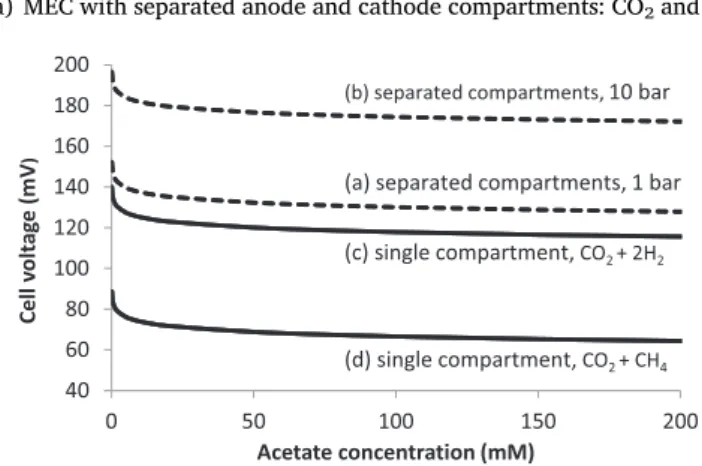
The evolution of the cell voltage as a function of the acetate con-centration is illustrated inFig. 1for three different cases:
(a) MEC with separated anode and cathode compartments: CO2and H2
Table 2
Different possible ways of writing acetate oxidation and related thermodynamic equations. By convention, reactions are written in the reduction direction. EAis the
equilibrium potential (V/SHE), EA0is the standard potential (V/SHE), EA0′ is the formal potential at pH 7.0 (V/SHE), pCO2is the CO2partial pressure (atm), which
was assumed to be equal to the fugacity, Ciare the concentrations of the i species (mol·L−1), which were assumed to be equal to activities, R (8.314 J mol−1K−1) is
the universal gas constant, T (K) is the temperature, and F (96 485 C·mol−1) is the Faraday constant. The standard potentials were calculated by using the standard
molar Gibbs energy of formation of each compound as detailed in the Supporting Information.
Reaction and equilibrium potential EA0(V/SHE) EA0′ (V/SHE)
pH 7.0 Standard conditions 1 2CO2+ 7H++ 8e−→ CH3COO−+ 2H2O
EA= EA10−2.38FRT7pH +2.38FRTlog CCH COOpCO2 2 3 0.071 −0.291 T = 298.5 K pH = 0 pCO2= 1 atm CCH3COO–= 1 M 2 2CO2,aq+ 7H++ 8e−→ CH3COO−+ 2H2O
EA= EA20−2.38FRT7pH +2.38FRTlog CCH COOCCO aq2, 2 3 0.093 −0.269 T = 298.5 K pH = 0 CCO2,aq= 1 M CCH3COO–= 1 M 3 2HCO3−+ 9H++ 8e−→ CH3COO−+ 4H2O EA= EA30−2.38FRT9pH +2.38FRTlog CHCO CCH COO3 2 3 0.187 −0.278 T = 298.5 K pH = 0 CHCO3–= 1 M CCH3COO–= 1 M
Fig. 1. Equilibrium cell voltages calculated with Eq.(7)versus acetate con-centration. Calculations were performed at pH 7.0 and a temperature of 298.15 K. Dashed lines: two-compartment MEC under 10 (b) or 1 atm (a) pressure in each compartment. Continuous lines: single-compartment MEC under 1 atm total pressure for the production of pure hydrogen (c) noted CO2+ 2H2, or the complete conversion of hydrogen to methane (d) noted
CO2+ CH4. In the case of methane production, the calculation was done with
partial pressures were equal to 1 atm in the anode and cathode compartments, respectively;
(b) the same two-compartment MEC configuration operated under 10 atm pressure: pCO2and pH2were both equal to 10 atm; (c) a single-compartment MEC: according to Reaction 6, the partial
pressures of H2and CO2were 0.67 and 0.33 atm, respectively.
The cell voltage is weakly dependent on acetate concentration, ex-cept for very low concentrations of a few millimolars (Fig. 1). It is consequently not very useful to increase the substrate concentration with the objective of favouring the thermodynamics. Implementing a single-compartment or a double-compartment reactor is pretty similar from a thermodynamic point of view.
Interestingly, Fig. 1 points out that operating the reactor under pressure increases the equilibrium cell voltage only slightly. Only around 40 mV are lost when the pressure is increased from 1 to 10 atm. It can consequently be very beneficial to operate an MEC under pres-sure so as to produce pressurized gas directly at the reactor outlet. The power lost in the MEC is much less than the power that would be re-quired for mechanical compression of the gas downstream. Moreover, microorganisms are generally not significantly sensitive to pressure up to very high values. For instance, high pressure processing, which is used for food preservation[52], must use pressures above 100 MPa – i.e. 1000 atm – in order to affect microbial populations[53]. It seems that there is no theoretical barrier to operating an MEC under pressure of several atm, although it has never been attempted so far to our knowledge. This may be a worthwhile research path for future MEC development.
2.2. Other advantages of MEC vs. water electrolysis
Microbial electrolysis has several well-known advantages. The electroactive biofilms develop spontaneously on the anode surface from the microbial species contained in the electrolyte. Consequently, forming microbial anodes does not require sophisticated electrode preparation steps as for most abiotic catalytic layers. Low cost electrode materials can be used such as some carbon-based materials. Microbial biofilms self-assemble and also self-sustain, allowing long-term MEC operation without maintenance[43]. They catalyse the electrochemical oxidation of a large variety of organic compounds[11–13].
An MEC that operates under appropriate control procedure (see
Section 3.10) does not produce oxygen. This advantage has rarely been emphasized so far, but it is a great advantage in terms of process safety with respect to water electrolysis. Actually, the concomitant production of hydrogen and oxygen is an important issue in water electrolysis that is no longer present in an MEC. This safety asset becomes even more important if the objective is to produce pressurized hydrogen, because high internal pressure in water electrolysis considerably increases the risk of hydrogen cross-over to the anode compartment[54,55]. In an MEC, hydrogen transport to the anode only decreases the energy yield but does not exacerbate safety issues.
Similarly, the anode of an MEC operates at too low a potential for the production of chlorine to become a risk. This is also an advantage, because the electrolyte does not need to be freed from the chlorine ions, as is required for conventional water electrolysis.
The pH of the MEC electrolyte must be around neutrality because microbial anodes rarely accept extreme conditions [56]. Acidic elec-trolytes are prohibited because electroactive biofilms are inhibited at pH values one or two units below 7[57–59]. On the other hand, the pH of the bulk electrolyte rarely reaches values above 10 in microbial electrochemical systems. The restricted range of pH around neutrality is clearly an advantage in terms of safety because the electrolyte can be handled easily without drastic precautions. It is, for instance, very much easier to replace and dispose of a phosphate solution at pH 7 rather than the KOH solution at pH 14 that is commonly used in alkaline water electrolysis cells.
2.3. MEC for methanation and microbial electrosynthesis
MECs for hydrogen production can also be the basis of electro-synthesis reactors for the production of a great variety of compounds. For example, hydrogenotrophic methanogenic Archaea can be set in the cathode compartment where they will use the hydrogen produced to reduce CO2to CH4[60,61]:
CO2+ 4H2→ CH4+ 2H2O (8)
In a single compartment MEC, CO2produced at the bioanode can
combine with hydrogen produced at the cathode[62]leading to the overall reaction:
CH3COO−+ H+→ CO2+ CH4 (9)
Actually, methane may be considered as a side-product that pollutes hydrogen production [19,49] and must consequently be avoided
[63,64,21,65]or, in contrast, MECs can be designed with the deliberate objective of producing methane[19,61,62].
The equilibrium cell voltage is plotted inFig. 1 for a single-com-partment MEC working in methanation (Reaction 9) under 1 atm total pressure, i.e. with CO2and CH4partial pressures of 0.5 atm each. In this
case, the equilibrium cell voltage depends on the residual H2partial
pressure present in the MEC. Logically, the more efficient methanogens are at consuming H2, the lower the H2partial pressure becomes and the
more the thermodynamics of hydrogen evolution is favoured. The curve was plotted for a hydrogen partial pressure equal to 0.01 atm. The equilibrium cell voltage becomes equal to zero for H2partial pressure of
10−4atm (P
CO2= 0.5 atm, CCH3COO−= 1 M, pH = 7.0, T = 298.15 K),
which means that the process would become spontaneous if the drogenotrophic methanogens were efficient enough to consume hy-drogen very fast and maintain very low hyhy-drogen partial pressure in the MEC.
Actually, the overall reaction (9) is identical to the acetoclastic pathway of methane production in anaerobic digestion. It is known that extremely low hydrogen partial pressure is required for this conversion to occur[66]. Here, the thermodynamics of the MEC shows that this conversion becomes spontaneous at very low H2partial pressure, as is
known in the context of anaerobic digestion.
The interest of implementing an MEC to produce methane as often been presented as a complement to anaerobic digestion (AD). It is generally claimed that MECs can operate with lower concentrations of substrate than AD so, for instance, effluents from a digester could be an appropriate inlet stream for an MEC[17,62,67,68]. Coupling MEC to AD has been shown to accelerate the degradation of some recalcitrant compounds and alter the AD microbial community thus increasing biogas production[16]. It can also be hoped that a two-compartment MEC would produce a biogas richer in methane than that obtained through anaerobic digestion and could also protect the methanogenic consortia against inhibitory compounds that may be present in the wastes used as feedstock[61].
Acetate, butyrate, caproate and other compounds can also be syn-thesized at the cathode by coupling the electrochemical production of hydrogen with a microbially catalysed reaction that uses hydrogen as electron donor. So-called microbial electrosynthesis cells have been shown to be able to convert CO2into various products[69–73]. Some
microbial electrosynthesis pathways are assumed to involve direct electron transfer from the cathode to the microorganisms [74] but mediation by hydrogen is often the main route[71,75].
The interest of coupling the electrochemical production of hydrogen with its microbially-catalysed utilization in the same reactor can be debated (see section 4.4). It has been argued that large-scale microbial electrosyntheses that involve hydrogen mediation would be better im-plemented via two separate reactors: an electrolyser for hydrogen production and, downstream, a gas-liquid contactor for the microbially-catalysed hydrogenation[75,76]. Here, the purpose is not to develop
= N G U J G
H2 c H0, 2
(10) where NH2 (mol·s−1·m−2) is the molar flux of hydrogen per unit cathode surface area, U (V) is the cell voltage, J (A·m−2) is the current
density and ΔG0
c,H2(J·mol−1) is the absolute value of the standard Gibbs free energy change for hydrogen combustion (237.1 kJ·mol−1)
In the context of pure hydrogen production, the objective is gen-erally to further use the hydrogen in fuel cells, which means that only the Gibbs free energy can be exploited. In this case, methane, which is often produced in MECs due to Reaction 8, is considered as a side-product that must be avoided or separated and is not considered in the energy balance.
In contrast, if hydrogen is intended to be burned, the thermal energy yield (γH) can be assessed by using the standard enthalpy change of
hydrogen combustion. Moreover, in this case, it may be useful to pro-duce a mix of hydrogen and methane, for instance to be intropro-duced into the gas distribution network. Both methane and hydrogen are used for their heat of combustion. The thermal energy yield γHis consequently
calculated by taking the enthalpies of combustion of both hydrogen and methane into account:
= N H +N H U J H H2 c H0, 2 CH4 c CH0, 4 (11) where ΔH0
c,H2is the absolute value of the standard enthalpy change of hydrogen combustion (286 kJ·mol−1), ΔH0
c,CH4is the absolute value of the standard enthalpy change of methane combustion (891 kJ·mol−1),
NH2 and NCH4 (mol·s−1·m−2) are the molar fluxes of hydrogen and methane per unit cathode surface area.
The maximum limit values of the two energy yields can be assessed by using the equilibrium cell voltage in Eqs.(10) and (11). It should be noted that this assumption, which is usually made in order to assess the maximum limits of energy yields, is completely theoretical because an electrolyser cannot produce anything under equilibrium conditions.
In order to calculate the theoretical, maximum limit values of the energy yields, the molar fluxes of H2and CH4were extracted from the
electron balance assuming that the Faradaic yields were equal to 100% at both anode and cathode. When 1 mol of electrons moves though the electrical circuit from the bioanode to the cathode:
– 0.25 mol of CO2is produced at the bioanode (Reaction 1), and x
mole can be transformed to CH4(Reaction 8)
– 0.5 mol of H2is produced at the cathode (Reaction 4), and 4x mole
can be transformed to CH4(Reaction 8)
– x mol of CH4can be produced by the combination of H2with CO2
(Reaction 8).
This simple mass balance leads to the expression of the molar flux given inTable 3.
In a 2-compartment MEC, it was assumed that no methane was produced, so x = 0 and the molar flux of hydrogen, equal toJ
F0.5, was
input into Eqs.(10) and (11). The values of the pressure of CO2and H2,
equal to 1 atm in each compartment, were used to calculate the equi-librium cell voltage (Eq.(7)), which led to the maximum values of the energy yield γGand the thermal energy yield γH(Eqs.(10) and (11))
reported inTable 4.
For a single-compartment MEC, calculations were made for various CH4partial pressures, from no production of methane (pCH4= 0) to the
total conversion of hydrogen to methane (pCH4= 0.5 atm). For each
value of CH4partial pressure, the value of x and the partial pressures of
H2and CO2were calculated by usingTable 5. The values of the H2and
CO2partial pressures were then used to calculate the equilibrium cell
voltage (Eq.(7)), which led to the maximum values of the energy yield γGand the thermal energy yield γH(Eqs.(10) and (11)) reported in
Table 4.
2.5. Comparison of MEC and water electrolysis in terms of theoretical energy yields
In a conventional water electrolysis cell, assuming 100% Faradaic yield at the cathode, the molar flux of hydrogen is equal to J/2F, so:
= G FU 2 G c 0 (12) Obviously, γG= 1 when U is set equal to the equilibrium cell
vol-tage of 1.23 V (ΔGc0= -237.1 kJ·mol−1). For water electrolysis, the maximum value of γGis equal to unity because the reaction of water
electrolysis
2H2O → O2+ 2H2 (13)
Table 3
Theoretical molar fluxes calculated with 100% Faradaic yields at both bioanode and cathode.
Gas molar flux N (mol·s−1·m−2)
H2 CO2 CH4 Total J F(0.5 − 4x) J F(0.25 − x) J Fx J F(0.75 − 4x) Table 4
Maximum energy and thermal energy yields for MECs and water electrolysis cell. The CO2and H2partial pressures were used to calculate the equilibrium
cell voltage Ueqwith Eq. (7). Calculations were performed with T = 298.15 K,
pH = 7.0 and acetate concentration = 1 M. For the MEC with complete con-version of H2to CH4, the partial pressure of hydrogen (pH2) was assumed equal
to 10−4atm.
Operating conditions Gas composition (atm) Ueq(V) Max. limit values
pCH4 pCO2 pH2 γG γH 2-Compartment MEC without CH4 production 0 1 1 0.123 10.0 12.1 1-Compartment MEC with production of various ratios of CH4 0 0.5 0.5 0.109 11.3 13.6 0.05 0.35 0.60 0.109 8.4 12.8 0.20 0.40 0.40 0.105 3.9 12.0 0.40 0.47 0.13 0.092 1.0 12.9 0.49 0.50 0.01 0.059 0.14 19.5 0.5 0.5 10−4 0 0 7223 Water electrolysis – – 1 1.23 1.00 1.21 Table 5
Theoretical partial pressures calculated with 100% Faradaic yields at both bioanode and cathode using the mass balance described inTable 3.
Partial pressures in a single compartment MEC (atm)
H2 CO2 CH4 Total 0.5 4x 0.75 4x 0.25 x 0.75 4x x 0.75 4x 1
this debate but only to illustrate the versatility of MECs, pointing out that consuming hydrogen in situ in the cathode compartment is bene-ficial to the thermodynamics.
2.4. Energy and thermal energy yields
The energy yield (γG) of an electrolyser that produces hydrogen is
generally expressed as the ratio of the energy that could be recovered from the hydrogen produced to the electric energy consumed to gen-erate it [77]:
One of the reasons for such poor performance has been the usual
choice to try to apply MECs to wastewater treatment. Domestics was-tewaters, which are the most commonly targeted for MEC feeding, have very low ionic conductivity, commonly of the order of 0.2 S·m−1,
sometimes less[79], and scaling up an electrochemical process with such poorly conductive electrolytes is an extremely tough challenge
[80,81]. Actually, an “abiotic” electrochemical engineer would con-sider it heresy to put wastewater into an electrolyser.
More generally, sustaining microbial growth in a culture medium and implementing an electrolyser for large-scale hydrogen production are two antagonistic objectives. The electrochemical processes devel-oped so far at industrial scale require the cleanest possible electrolytes, with the simplest possible chemical composition, in order to avoid deposit on the electrode surfaces and inhibition of the electrode cata-lysts. Abiotic electrocatalysts are generally very sensitive to any form of inhibition by adsorption of chemical compounds and would quickly lose their effectiveness in a culture medium. Moreover, electrolytes for water electrolysis are strongly acid or alkaline. At the opposite extreme, sustaining microbial growth requires neutral pH and chemically rich media. Culture media must contain a large number of ions, including Ca2+ and Mg2+, which can result in hydroxide deposits and many
chemical compounds that may adsorb on electrode surfaces. Here is the stumbling block of the whole enterprise: the two objectives are com-pletely antagonistic.
3.2. Current density or volumetric production rate?
When reading the literature on MECs, an electrochemical engineer is surprised at not always finding the values of current density, while values of volumetric hydrogen production rates are generally reported. Physically, current and hydrogen production are not extensive variables relating to the reactor volume. Increasing the electrolyser volume does not increase the hydrogen production if the electrode surface area is not increased. For this reason, using the volumetric hydrogen production rate may lead to wrong conclusions. For example, a bioanode of 1 cm2
surface area working at 100 A·m−2in a reactor of 200 mL gives a
vo-lumetric hydrogen production rate of 0.5 N LH2L−1d−1 (assuming
100% Faradaic yield). In comparison, a bioanode of 100 cm2working at
only 1 A·m−2 in a reactor of 100 mL, produces 1 N L
H2L−1d−1.
Comparing these two systems by using the volumetric production rates would lead to the erroneous conclusion that the second bioanode per-forms better and may incite a designer to abandon the most promising bioanode able to provide 100 A·m−2. In the case of electrochemical
processes, the volumetric production rate is dependent on the reactor configuration, so it can completely skew the assessment of the electrode efficiency.
Current density must be used to characterize any electrochemical process. A glance at one of the pillars of electrochemical engineering literature can convince the reader of this[77]. In this book, the dif-ferent industrial electrochemical processes are always described and compared in terms of current density. Other major parameters are also indicated, such as voltage, energy consumption, inter-electrode dis-tance, and electrode surface area, but there is no mention of volumetric production rates.
It should still be kept in mind that volumetric production rates can be useful for specific purposes, mainly if the objective is to improve the compactness of reactors or to compare the area footprint of two sys-tems. Similarly, for instance, the production rate per unit reactor weight becomes a major parameter for transportation and spatial applications. Nevertheless, such parameters address only specific targets, linked to given application. To contribute to the general development of MECs, the multidisciplinary research community should be advised to use current density systematically as the main parameter for characterizing and comparing MECs.
is exactly the reverse of hydrogen combustion.
The maximum limit values are assessed by assuming that electro-lysers operate at the equilibrium cell voltage. Close to equilibrium, water electrolysis is an endothermic reaction. Water electrolysis should consequently be provided with heat so as to occur close to the equili-brium cell voltage. Nevertheless, the power that should be provided in the form of heat for water electrolysis to occur close to the thermo-dynamic equilibrium is not taken into account in the calculation of the thermal energy yield. For this reason the thermal energy yield can theoretically be greater than unity, as reported in Table 4 (γH = 1.21).
In an MEC, hydrogen is produced by Reaction 6, which is not the reverse of hydrogen combustion. This reaction requires considerably less electrical energy than water electrolysis, so the energy yields can be significantly higher than unity, up to 10 or 11.3 for γG depending on the
MEC design (Table 4). Another way to explain the yields higher than unity is to say that an MEC takes advantage of two sources of energy, the energetic power and the chemical energy contained in the com-pounds that are oxidized at the bioanode. Only the electric energy is taken into account when assessing the energy yield. This approach is justified when the compounds oxidized at the bioanode are waste or-ganic matter that must be treated. The yield equations would have to be modified if more valuable compounds were oxidized at the bioanode.
When the side-production of methane is enhanced, the energy yield, γG, which is related to hydrogen only, logically decreases (Table 4). In
contrast, the thermal energy yield, γH, which takes the contributions of
both hydrogen and methane into account, remains close to 12. This stability is the result of two antagonistic effects. On the one hand, the increase in methane ratio decreases γH because 4 molecules of hydrogen
are required to form one molecule of methane (Reaction 8) but the standard enthalpy of methane combustion (891 kJ·mol−1) is less than
four times that of hydrogen combustion (286 kJ·mol−1). On the other
hand, by decreasing the partial pressure of hydrogen, the production of methane decreases the equilibrium cell voltage.
Finally, if the production of methane is very fast with respect to hydrogen evolution, the hydrogen partial pressure would tend to zero. In theory, the thermal energy yield would therefore tend to infinity (in
Table 4 it is equal to 7223, when using a hydrogen partial pressure of 10−4 atm). This limiting case has a fundamental interest because it
tends towards spontaneous anaerobic digestion. This is beyond the scope of a MEC. It might be speculated that this limiting case may be close to the field o f e lectro-fermentation, i n w hich e lectrical power intervenes by non-Faradaic pathways [78], which would result in considerable energy yields, although the meaning of electrical energy yield may be debate in this case.
The great values of the energy yields illustrate the interest of MEC technology. Energy yields up to 10 or 11 may theoretically be hoped for when considering only the production of hydrogen. This means that more than 10 times the electric power that is provided to the MEC is stored in hydrogen in the form of Gibbs free energy. This energy yield decreases significantly w hen t he s ide-production o f m ethane i s not avoided but, in this case, the production of a hydrogen-methane mix keeps the thermal energy yield close to 12 for applications based on gas combustion.
3. The engineering challenges that must be tackled if the thermodynamics is to fulfil its promises.
3.1. An antagonism linked to the very essence of MEC
A large gap exists between the theoretical hopes and the experi-mental realizations. A glance at Table 1, which relates MEC pilots with volumes of at least several litres, confirms that hydrogen can be pro-duced with cell voltages lower than that required for water electrolysis. Nevertheless, current densities remain dramatically low, often less than 1 A·m−2.
process, in which the potential is used to control the redox state of the microbial cells [78]. In this case, the current does not provide the charge necessary for conversion but it indirectly orients the catalytic pathway. Will it be possible to find such an innovative process for hy-drogen production, for which maximising current density may not be the main requirement?
To sum up, two different research strategies must be explored to develop MEC. On the one hand, ground breaking concepts may be discovered, which might overcome the need to maximize the current density. This path remains open. On the other hand, if the objective is to adapt conventional electrolyser architectures to microbial catalysis, increasing current density must be considered as the main purpose. 3.4. Faradaic yields are useful tools for identifying operating issues in MECs
At the anode, the Faradaic yield expresses the ratio of the amount of electrons that are provided to the electric circuit to the total amount of electrons that could be extracted from the substrate oxidation. A glance at Table 1shows a few anode Faradaic yields that are considerably higher than 100%. This phenomenon has been attributed to hydrogen cycling[39,45,85,86]. Hydrogen produced at the cathode reaches the anode, where it is oxidized:
H2→ 2H++ 2e− (14)
Although never evoked in the context of MEC yet, a similar scheme can also be postulated with methane. Methane results from the com-bination of H2 produced at the cathode with CO2 produced at the
bioanode (Reaction 8), and could be oxidized at the bioanode[87,88]:
CH4+ 2H2O → CO2+ 8H++ 8e− (15)
Anode Faradic yields above 100% reveals MEC dysfunction. This is an important issue which can cause significant hydrogen/methane loss. At the cathode, the Faradaic yield is generally related to hydrogen production. It expresses the ratio of the amount of electrons that could be recovered from the hydrogen produced to the electrons that circu-lated in the electrical circuit. It can be anticipated that cathode Faradaic yields will be close to 100%, because it is difficult to see that any re-action other than the reduction of water/proton could occur at the cathode. Actually, the electrochemical reduction of CO2, to formate for
instance, would be possible[89,90]but has not been evoked in the case of MECs and is unlikely because of low partial pressure of CO2.
Table 1shows that cathode Faradaic yields most often ranging from 50 to 80%. These low values are due to the consumption of hydrogen either in the bulk (Reaction 8) or at the anode (Reaction 14), because cathode Faradaic yields are calculated using the hydrogen flow out of the reactor and not the hydrogen flow that is produced at the electrode surface. The low values of the cathode Faradaic yield essentially in-dicate the extent of the hydrogen consumption by side-reactions, or even hydrogen leaks, rather than being related to the electrochemical process of hydrogen evolution.
An extremely high value of the H2 Faradaic yield (552%) is also
reported inTable 1. It corresponded to the spontaneous production of hydrogen by sugar fermentation[41]. In this case the electrochemical process may play a minority role in hydrogen production. Substrates that contain fermentable compounds, such as sugars, may lead to strong overestimation of the contribution of the electrochemical process to hydrogen production. This issue should be systematically addressed when implementing substrates that include a fermentable part or when the composition of the substrate is not well mastered. It points out the necessity to perform control experiments at open circuit in order to assess the possible production of hydrogen and methane by microbial processes in the absence of electrochemical assistance. This is an im-portant difference with water electrolysis, for which control experi-ments at open circuit are obviously useless. In contrast, such control experiments should be systematically performed for MECs that use 3.3. Why should increasing current density be a major goal?
In the general context of chemical engineering, heterogeneous processes using a solid catalyst are known to be one level more complex than homogeneous processes. Considering that an electrochemical process is based on two different h eterogeneous c atalytic reactions, which are interdependent, shows that its complexity is at least two levels higher than that of a homogeneous process. Consequently, re-placing a homogeneous process by an electrochemical process can only be planned if considerable benefits are expected.
An electrochemical reactor is sophisticated piece of equipment, which is delicate to design and to implement. It requires two electrodes to be designed, generally set face to face, with an inter-electrode dis-tance as small as possible to reduce the ionic resisdis-tance of the electro-lyte. Maintaining uniform hydrodynamics within the narrow compart-ment(s) is difficult and costly in terms of pumping energy. The reactor must include several electrical connections and possibly large current collectors when the intrinsic conductivity of the electrodes is not high enough. Sometimes a separator is needed. Technically, such an ar-rangement needs many seals and rigid frames held by strong presses or a multitude of screws. Dismantling them is a labour-intensive opera-tion, which may be quite frequent because electrodes wear out or are damaged by deposits. The maintenance is time-consuming and requires a high level of technical training. In addition, passing electricity through solutions is always a sensitive safety issue. Ohmic losses due to electrical connexions and the peripheral electrical set-up can be sig-nificant.
All these issues are exacerbated when the electrode surface becomes larger. Larger electrode surface area means greater likelihood of clog-ging or leakages, greater difficulty in ma intaining fla tness, higher number of connexions, more delicate and longer disassembly/re-assembly operations, higher risk of stray currents… These are the rea-sons why ensuring high current density is the main objective that is targeted when designing electrolysers. Reducing the surface area of electrolysers is essential to allow their industrial development for the production of chemicals.
The case of water electrolysis can illustrate this situation. Actually, it would be possible to design low-cost water electrolysis reactors working at low current density. Alkaline electrolysers could work per-fectly at low current density with cheap electrodes made of low grade steel. Furthermore, operating at low current would decrease the ohmic losses and could compensate the overpotential losses due to the absence of catalyst on the electrodes. Hydrogen produced at low current density in low-cost water electrolysers would not be more expensive than that produced in reversed PEM fuel cells, which can work at more than 10,000 A·m−2. Nevertheless, low-cost water electrolysers working at
low current density have never been contemplated for large-scale in-dustrial development. On the contrary, researchers are still trying to improve electrocatalysts in order to increase current densities. This is not because of an irrational desire for high technology, but because ensuring high current density is an imperative for scaling-up industrial electrolysers to be used for large-scale hydrogen production, even for a reaction as simple as water electrolysis.
Obviously, this essential rule, established for large-scale production electrolysers, should be qualified, particularly in the context of micro-bial electrochemical technologies. One of the fascinating aspects of microbial electrochemical technologies is their capacity to generate ground breaking concepts. Microbial electrochemical technologies can thus be the source of new electrochemical processes that do not have ensuring high current density as a prerequisite for their development. For instance, microbial electrochemical snorkels [82,83] can be de-veloped at large scale on the basis of low current, because they can be designed according to an extremely simple configuration. They can be considered as simple conductive biofilters [84], which do require nei-ther a sophisticated arrangement nor specific care. Anonei-ther example is electro-fermentation, a non-Faradaic microbial electrochemical
= FN + FN J
2 H 8 CH
cath 2 4
(16) where F (96,485 C·mol−1) is the Faraday constant, N
H2 and NCH4 (mol·s−1·m−2) are the molar fluxes of hydrogen and methane per unit
cathode surface area, and J is the current density (A·m−2).
Values of Φcath above 100% indicate the side-production of
hy-drogen and/or methane by non-electrochemical pathways, as was the case for several MEC pilots reported inTable 1. In such cases the energy and thermal yield values keep some practical meaning, because any source of production is obviously welcome, but the contribution of electrochemistry, if any, cannot be evaluated. In a few extreme cases, where Φcath exceeds 200%, electrochemistry makes a minority
con-tribution (unless there is an electro-fermentation effect[78]). On the other hand, it should be noted that a Φcathvalue lower than
100% does not prove definitively that no microbial hydrogen and/or methane side-production occurs, because of the possible conversion of hydrogen to other compounds. Calculating Φcathcannot replace
open-circuit control experiments.
In conclusion, the anode Faradaic yield and the overall H2Faradaic
yield are easy-to-calculate parameters that allow the direct detection of possible dysfunctions such as H2 re-cycling at the anode, H2
con-sumption in the bulk, and H2 side-production by fermentation.
Apparently, these dysfunctions often occur in MEC pilots (Table 1). On the other hand, the overall cathode Faradaic yield should be used sys-tematically to detect possible side-productions of hydrogen and/or methane.
3.5. Electrolyte: a key issue
As explained inSection 3.1, polluting the electrolyte with so dirty medium as one suitable for microbial growth appears a very curious idea to an “abiotic” electrochemical engineer. It seems even more sur-prising that the majority of MEC pilots have been applied to the treatment of effluents and wastewater (Table 1)[28,36]. These media have very low ionic conductivity, commonly of the order of 0.2 S·m−1,
sometimes less [79], which makes the design of efficient electro-chemical cells extremely difficult[80,81]. Higher current densities, of 1.35 A·m−2, have been obtained with MEC pilots by adding phosphate
buffer into the effluent [41], and using a synthetic medium supple-mented with acetate as the substrate has given up to 10 A·m−2[91]. To
the best of our knowledge, the highest current density reached with an MEC several litres in volume, of 42.5 A·m−2, was obtained by using a
high concentration of salt (35 g/L NaCl) to attain a fair ionic con-ductivity of 9 S·m−1[48].
Low conductivity of the electrolytes is a major reason for the poor performance reported so far with large-sized MECs [80,92]. At low ionic conductivity, it is very important to optimize the MEC archi-tecture in order to permit the electrodes to work in conditions that are the least detrimental possible[93]and increasing size inevitably leads to a rapid decrease in performance[81].
To overcome this major obstacle, many attempts have been made to develop microbial anodes able to operate in saline and hypersaline media[48,94–97]. According to a recent review[98], the most efficient halotolerant microbial anodes have been prepared with inocula coming from salt marshes[99–101]. These microbial anodes produced up to 85 A·m−2under polarization at 0.1 V/SCE with acetate 40 mM. They
operated in media containing NaCl at 45 g·L−1 with an ionic
con-ductivity of 10.4 S·m−1, i.e. a value of the same order as those used in
water electrolysis. For instance, the ionic conductivity of a thin PEM is around 10 S·m−1and the 20–30% KOH electrolytes commonly used in
alkaline water electrolysis can reach 60 S·m−1[5].
The major components of the electrolyte used to develop this ha-lotolerant microbial anode were NaCl 45 g·L−1(770 mM), CH
3COONa
(40 mM), NH4Cl (37 mM) and phosphates (3 mM)[101]. The transport
numbers (Table 6) indicated that, in the solution bulk, far from the concentration gradients occurring in the vicinity of the electrode sur-faces, 95% of the current was carried through the electrolyte by the motion of Na+to the cathode (37.9%) and of Cl−to the anode (57.5%).
NaCl played its role of current carrier through the electrolyte perfectly. It may be recalled that, as observed inTable 6, neither H+nor OH−
help to carry electricity through the electrolyte. Their concentrations are too low around neutral pH to have any effect on the ionic transport of electricity[79]. Rigorously speaking, the salt marsh inoculum added at 5 to 10% v/v into the medium should modify the accurate dis-tribution of the transport numbers, mainly with the addition of small concentrations of sulphate, magnesium and calcium ions. Nevertheless, these small disturbances should not modify the general situation de-scribed here.
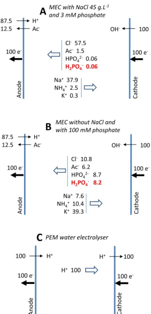
The ionic transport through the electrolyte can be outlined by means of the ion fluxes expressed on the basis of 100 electrons ex-changed at the electrodes. When 100 electrons are transferred to the anode, 12.5 molecules of acetate are consumed and 87.5 protons are produced at the bioanode (Reaction 1), while 100 hydroxide ions are produced at the cathode (Reaction 4). To compensate for the ion im-balance thus created, 57.5Cl− and 1.5 CH
3COO− ions move to the
anode, while 37.9Na+ and 2.5 NH
4+ ions move to the cathode
(Fig. 2A). This emphasizes a crucial problem: migration does not con-tribute to pH balance at the electrodes. The phosphate species, which were present in this medium at only 3 mM, played no significant role in ionic transport through the bulk of the electrolyte.
The protons produced at the anode are not driven away from the anode zone by migration and they are not neutralized by the migration of buffering species to the anode. The flux of H2PO4−ions, the only
species which could mitigate the anode acidification is only of 0.06 ion for 100 electrons exchanged. Similarly, the OH−ions produced at the
cathode are not driven away by migration. The anode vicinity acidifies and the cathode vicinity alkalinizes, and only diffusion due to the concentration gradients can mitigate anode acidification and cathode alkalinization.
From a thermodynamic standpoint, cathode alkalinization is detri-mental to the hydrogen evolution reaction rate (Reaction 4). In addi-tion, alkalinization of the cathode vicinity is a specific problem for MECs, because cations such as Ca2+and Mg2+, which are required to
sustain the bioanode, deposit in the form of hydroxides on the cathode Table 6
Transport numbers in the bulk of the electrolyte for a saline electrolyte com-posed of NaCl 45 g·L−1, CH
3COONa 40 mM, NH4Cl 37 mM and phosphates
3 mM, pH 7.5[101]. The molar ionic conductivities are taken from the Hand-book of Chemistry and Physics[102]. Transport numbers were calculated ac-cording to: ti= iCi
k k Ck
as described in[79], where σ = C
k k k= 10.7 S·m
−1is
the theoretical ionic conductivity of the medium.
Ion Concentration
Ci(mM)
Molar ionic conductivity λ0 i(10−4m2·S·mol−1) Transport number ti(%) Na+ 810 50.1 37.9 NH4+ 37 73.5 2.5 K+ 4.2 73.5 0.3 Cl− 807 76.3 57.5 CH3COO− 40 40.9 1.5 H2PO4− 1.8 36 0.06 HPO42− 1.2 114 0.13
complex substrates, which may contain fermentable compounds. In the absence of such control experiments, evaluations of the en-ergy and thermal yields should be considered with caution, because a part of the hydrogen and/or methane production may result from mi-crobial processes that have nothing to do with electrochemistry. To detect this type of situation, we suggest calculating the overall cathode Faradaic yield (Φcath), defined as the ratio of the electrons that could be
recovered from the hydrogen and methane produced to the electrons circulating in the electrical circuit:
surface. Salt precipitation and chemical fouling of the cathode surface is known to be a severe drawback in microbial electrochemical processes
[103–105,50].
In a microbial fuel cell, bubbling CO2inside the cathode
compart-ment has been successfully used to reduce the pH and reducing the overpotential related to oxygen reduction[106]. In an MEC, the same process also succeeded in reducing the bulk pH but had a limited effect on the cathode overpotential[107]. It was suspected that the pH may have kept high local value near the cathode surface.
Anode acidification is an even more crucial issue because, in addi-tion to the detrimental effect on the thermodynamics, microbial anodes are severely inhibited, or even deteriorated, at slightly acid pH values
[57,59].
In the medium used in the previous works to form efficient halo-tolerant anodes, the low ability to mitigate anode acidification may be attributed to the low concentration of phosphates. Nevertheless, even if the phosphate concentration was increased to 100 mM, or more, the situation would be only slightly improved. For instance, with 100 mM of phosphate species, 1.7 H2PO4−ions migrate towards the anode for
100 electrons exchanged (Table S3 in supporting information). Actu-ally, the problem is exacerbated by the heavy addition of NaCl. Using high salt concentration in the supporting electrolyte is a usual practice in order to increase the electrolyte ionic conductivity, which was equal to 10.7 S·m−1here (Table 6), but, in return, it decreases the migration
flux of the buffering species to the anode. In the absence of NaCl, the H2PO4−ion migration flux would increase to 8.2 (Fig. 2B), but the ionic
conductivity of the medium would fall to 2.6 S·m−1(Table S3 in
sup-porting information). The detrimental effect of high salt concentration has already been observed experimentally[108].
The usual practice of adding salts into the medium may conse-quently not be optimal in the MEC context. Of course, high salt con-centration increases the ionic conductivity of the electrolyte but, in return, it decreases the capacity of the migration to mitigate anode acidification, and local pH decrease is a major rate-limiting step for microbial anodes. An interesting way to optimize the electrolyte for MEC may be to increase the buffer concentration to the maximum tolerated by microbial anodes, instead of adding massive amounts of non-buffering salts. Moreover, increasing phosphate concentration should have a double beneficial effect: migration of HPO42−species
would mitigate the bioanode acidification on the one hand, and the presence of hydrogenated phosphate species would enhance the homogeneous catalysis of hydrogen evolution at the cathode (Section 3.7) on the other.
Because of the variety of ions contained in the electrolytes used in MEC, the ion migration fluxes will remain far from the ideal case of PEM electrolysers (Fig. 2C). PEM fixes the anions in its structure, so that only protons migrate through the electrolyte and proton migration fully balances proton production at the anode and proton consumption at the cathode. The sensitivity of microbial anodes to local acidification is a major issue for MECs. Accordingly, mastering ion transport with the objective of mitigating the anode acidification will remain a major challenge in developing MECs able to work at high current density. 3.6. Anode material and morphology
3.6.1. Material
The question of anode material has been widely studied, which has led to many comprehensive review articles[109–113]. Carbon-based materials have undoubtedly been the most widely used and have commonly led to efficient microbial anodes [112,114,115]. Un-fortunately, the modest electronic conductivity of these materials would make it necessary to use metallic current collectors if large surface areas were to be implemented. For this reason, metallic anodes are interesting alternatives [116,117]. Stainless steel has shown a promising capacity to form microbial anodes[116,118–120], particu-larly in the form of foam[121]. Nevertheless, if a high concentration of salt is used, chloride ions strongly increase the risk of pitting corrosion. If the potential of the anode is not accurately controlled (seeSection 3.10) severe corrosion can occur. Copper does not seem really suitable although it has shown excellent ability to form microbial anodes[117], because, with a standard potential of dissolution of 0.34 V/SHE (0.1 V/ SCE), the anode potential would have to be controlled very accurately and any accidental drift towards high values could cause the release of Cu2+ ions into solution. These ions are severely toxic for microbial
cells. Copper-polymer hybrid compounds may be an interesting alter-native[122].
Titanium is known to be unsuitable for anode applications because its passivation layer is poorly conductive. The problem has been solved by coating titanium with metal oxides such as ruthenium and tantalum oxides[123]to design so-called dimensionally stable anodes (DSA). A few studies have described DSA-supported microbial anodes[124–126]
but the use of DSA to support microbial anodes remains poorly docu-mented as yet.
Fig. 2. Ion fluxes due to migration. The numbers of ions are calculated on the
basis of 100 electrons passing through the electrical circuit. (A) Saline elec-trolyte composed of NaCl 45 g·L−1, CH
3COONa 40 mM, NH4Cl 37 mM and
potassium phosphates 3 mM, pH 7.5[101]; (B) same electrolyte without NaCl and with potassium phosphates 100 mM; (C) PEM electrolyser.
3.6.2. 2-dimensional vs. 3-dimensional
The interest of using porous electrodes to form microbial anodes has been emphasized by numerous studies, as reviewed recently[110,113]. Nevertheless, some studies comparing 2-dimensional and 3-dimen-sional electrodes in identical conditions have cast some doubt on the actual benefit provided by the 3-dimensional structures, either with multi-species communities [127] or with pure cultures [128]. This important issue would deserve further research because it may be a key factor for increasing the performance of microbial anodes. For instance, a multilayer structure has allowed current density to be boosted to 390 A·m−2 [129]. Could multi-layered structures, with internal
dis-tances of the order of several millimetres, constitute a better option than porous structures with sub-millimetre pores? This will be a major question for future research, and work has started to establish re-lationships between the optimal 3-dimensional structure and the phy-sicochemical and microbial characteristics of the system[130]. 3.6.3. Surface topography
The performance of microbial anodes can also be improved by working on the topography of the surface[131]. Actually, surface to-pography has often been considered as an important parameter in the development of efficient electroactive biofilms[118,132–135]but its impact is generally embedded in more complex surface modifications. Studies specifically devoted to the electrode surface topography, iden-tified as the main and, if possible, the sole parameter to be addressed, have been rare so far. Recent studies carried out with gold have shown that the current density can be multiplied by a factor close to 7 with random micro-roughness[136]and close to 10 by micro-structuring of the electrode surface[137]. These studies were performed with pure cultures of Geobacter sulfurreducens and addressed the early phase of biofilm formation. In contrast, aged multispecies biofilms have shown non-significant sensitivity to surface micro-roughness [138]. These various results illustrate the great interest of developing this research direction.
3.6.4. Chemical surface modification
Many studies have chemically modified the electrode surface in the aim of enhancing interfacial electron transfer from the biofilm to the anode material. This issue has been the subject of several reviews
[139–141,110,142]. However; it can be feared that some chemical modifications may be difficult to scale up to large sized electrodes in an economically efficient way. This issue should be considered with some care when the objective is to propose industrially-oriented strategies. 3.6.5. Biofilm redox properties
Preparing the most efficient possible electrocatalytic layers has been a major field of research and development in electrochemical en-gineering. In contrast, in microbial electrochemical technologies, the catalytic layer is the electroactive biofilm that develops on the electrode surface spontaneously and the means of action to make the biofilm do what the engineer would like it to do are limited. How can the biofilm be made to select for the most efficient electroactive species from a multispecies medium[143,144]? How can it be forced to form the most electron conductive matrix[145–148]? The applied potential may be a tool that helps to achieve this objective[149,150]but may not always be effective [151,152]. This item is still under debate[153,154,101]
(see a short review in[114]). The electron transfer capacity of a biofilm matrix may also be improved by developing it around ultra-micro-electrodes [155]. Increasing the electron transfer capability of micro-bial anodes is currently a hot research topic, which is mainly turned towards understanding the basic processes, but guidelines are still lacking for the engineer who wants to drive the electroactive biofilm towards maximum performance.
3.7. Cathode material and homogeneous catalysis of hydrogen evolution The choice of the cathode material of MECs has also been the sub-ject of many studies[26,37,156,157]. Platinum is clearly expensive and loses a large proportion of its catalytic capacity for hydrogen evolution at the neutral pH values that are imposed by microbial anodes. Stainless steel, nickel and cobalt alloys have been detected as promising candi-dates[158–162]even though they, too, remain quite expensive.
Porous materials have sometimes been proposed as MEC cathodes, with the objective of increasing the surface area available for hydrogen evolution. This solution may be successful at the laboratory scale, but cannot be adopted for high current density. At high current density, the bubble coverage (the fraction of the electrode surface area covered by adhering bubbles[163]) would decrease the effective conductivity of the interstitial electrolyte [164] and finally coalesce in the porous structure, blocking the electrode. Using a porous electrode to evolve gas is generally not an industrial option, unless the electrolyte is forced through it[164].
A homogeneous catalysis of hydrogen evolution is possible, based on using weak acids[165,166]. Weak acids, such as phosphates[166], release hydrogen atoms by electrochemical deprotonation on some metallic surfaces:
H2PO4−+ e−→ HPO42−+ ½ H2 (17)
This reaction produces hydrogen and the fast acid-base equilibrium that follows:
HPO42−+ H2O → H2PO4−+ OH− (18)
results in the overall reaction of water reduction:
H2O + e−→ ½ H2+ OH− (19)
Carbonates have been shown to have the same capacity[167]. This reactional pathway, called cathodic deprotonation reaction [166], corresponds to a homogeneous catalyst for water reduction: the water molecule no longer interacts with the electrode but the weak acid molecule ensures electron transfer with the electrode material. Less energy is required to extract the hydrogen atom from the acid molecule than from the water molecule. This catalytic pathway is particularly effective on mild steel[168]and stainless steel[166,167]surfaces. It decreases the overpotential necessary for hydrogen evolution, working around neutral pH, using cathodes made of steel, which can be less expensive than nickel alloys. Stainless steel has been widely used as cathode material in large scale MECs. Of the eight different pilots re-ported in Table 1, seven used stainless steel cathodes
[39,43–45,48,49,51]. Furthermore, phosphate is contained in many electrolytes used in the laboratory to develop microbial anodes, which makes this system highly suitable for MECs[169]. In fact, this kind of catalysis might already have happened in some MECS without being identified[170].
In the current state of the art, we would advise choosing a stainless steel cathode coupled to the homogeneous catalysis of hydrogen evo-lution by weak acids[171]. Nevertheless, the choice of steel grade is not easy. Using highly saline medium to decrease the ohmic drop in-duces a high risk of pitting corrosion because of the high concentration of chloride ions. Actually, the potential imposed on the cathode during MEC operation protects it against corrosion and a low grade stainless steel could be used. Nevertheless, any accidental interruption of the applied potential may lead to fast corrosion of low grade stainless steels. To avoid the risk of accidental corrosion, a high-grade stainless steel may be preferred, e.g. 254 SMO (EN 1.4547; ASTM UNS S31254), which can resist corrosion in marine environments thanks to its mo-lybdenum content, but at higher price. The choice may be some kind of wager on the confidence that can be placed on the operating procedure.