an author's
https://oatao.univ-toulouse.fr/26731
https://doi.org/10.1016/j.compositesa.2020.105806
Nguyen-Dinh, Ngoc and Hejjaji, akshay and Zitoune, Redouane and Bouvet, Christophe and Salem, Medhi New tool
for reduction of harmful particulate dispersion and to improve machining quality when trimming carbon/epoxy
composites. (2020) Composites Part A: Applied Science and Manufacturing. ISSN 1359-835X
New tool for reduction of harmful particulate dispersion and to improve
machining quality when trimming carbon/epoxy composites
N. Nguyen-Dinh
a,b, A. Hejjaji
a, R. Zitoune
a,⁎, C. Bouvet
a, M. Salem
aaInstitut Clément Ader (UMR CNRS 5312), Université de Toulouse, INSA– ISAE-SUPAERO– IMT Mines d’Albi – UPS, Toulouse, France bFaculty of Mechanical Engineering, Thai Nguyen University of Technology, Viet Nam
Keywords:
Polymer-matrix composites (PMCs) Defects
Electron microscopy
Dust dispersion, Respiratory hazard, Air contamination
A B S T R A C T
Conventional machining of carbonfiber reinforced plastic composites (CFRPs) generates minute chips that get suspended in air causing a hazard compromising operator safety. This study investigates the influence of cutting parameters (feed speed, cutting speed, radial depth of cut, tool geometry and tool wear) during trimming of CFRP on the form and quantity of harmful particles dispersed. Also, performance of two classical PCD tool geometries (two straightflutes, two helix flutes) have been compared with newly designed (in collaboration with ASAHI Company) four serrated straightflutes for the purpose of dust emission reduction. The quantification of the number of harmful particles was estimated using laser spectroscopic dust monitor. The results reveal that, trimming with a combination of higher feed speed and lower cutting speed can reduce the dispersion of harmful particles. Further, the four serrated straightflutes recorded the least number of harmful particles compared to the conventional tools.
1. Introduction
Fiber Reinforced Plastics (FRPs) are an advanced class of composite materials which have been widely used in various industrialfields (like aerospace) because of their high strength to weight ratio, high stiffness to weight ratio and anti-corrosion properties. To conform to different geometrical requirements for different applications, the composites are often manufactured to near net shape. However, after the manu-facturing and demolding of the composite part, machining operations are necessary to get thefinal dimensions with required tolerances. To accomplish the required geometric tolerances conventional or non-conventional machining operations may be employed[1–4]. The con-ventional methods include process like: trimming (milling) and drilling
[1,2,4,5] and non-conventional methods include processes like laser machining, abrasive waterjet machining etc [3]. Irrespective of the methods employed, machining composites is a difficult task and is al-ways accompanied with induced defects like delamination, fiber-pull out, uncutfibers and craters[5,6,8]. In addition to physical defects, the high temperature generated during conventional machining gives rise to thermal defects like matrix degradation and matrix burnout [4,7]. These machining induced defects critically deteriorates the surface in-tegrity of the machined component[9]. In fact, machining of composite materials is accompanied by a series of brittle fractures and different fracture mechanisms of the matrix and fibers material during the
cutting process which are the causes for some of the defects mentioned above[10,13]. In addition, the brittle and heterogeneous nature of the carbonfibers favors the generation of chips which are characterized by minute sizes, hence they are qualified as microchips during the process of cutting[12]. In addition, the fiber orientation with respect to the cutting speed direction has a great influence on the chip size and morphology as it decides the rupture mode[11]. Also, it is important to mention that, machining of CFRP composites without any lubricant (dry machining) is usually recommended by the companies. However, dry machining favors a rise in the appearance of machining induced damage, increases the rate of tool wear and above all the emission of fine workpiece dust particles (microchips) with extremely small sizes and sharp edges into the air[14]. If we refer to the literature, the major challenge faced during trimming of CFRP is damage generation, which can be summarized as: delamination, intra and inter-laminar cracks, uncutfibers, broken fibers, thermal and/or mechanical degradation of the matrix. However, the research community has ignored another main aspect of machining composites, i.e. the emission offine dust particles. The increasing use of composite materials in the industry leads to higher production rates and hence more frequent exposure to fine dust particles. These dust particles suspended in the air are deemed to be carcinogenic and they also pose a potential ability to damage the respiratory system and cause toxic irritations. Hence, it is of paramount importance to identify the main factors responsible for generation of
https://doi.org/10.1016/j.compositesa.2020.105806
⁎Corresponding author.
harmful particles in order to minimize the emission of these dangerous particles in the industrial environment during machining of CFRP. In fact, based on the industrial environmental regulation, the number of particles in one liter of air must be below a critical value in order to protect operator from occupational health hazards[15]. Surprisingly, this issue of dust particles resulting from machining of composite ma-terials has been ignored by the research community from long time. Indeed, only few studies related to the dust particles quantification are available in the literature[16,17]during milling or trimming of com-posite materials. One of the preliminary studies of dust particles is documented by Wagman et al.[16]. In this research, the morphology study of the particles (microchips) collected after machining graphite/ epoxy composites machined using two processes, i.e. drilling and sawing, was conducted. The results show that the particles generated by drilling can be considered as not harmful owing their size, which are characterized by lengths between 50 µm and 100 µm. However, the chips generated after sawing are shorter and harmful due to their mi-croscopic size (from 6 µm to 8 µm). It is important to notice that, in both the cases of machining, particles generated are in the form offibers embedded in matrix material and also freefibers. In another research, Boatman et al.[17]have worked to identify the impact of the nature of composite materials on the size and the number of harmful particles during trimming process. For this, two kinds of composite materials, CFRP and GFRP, have been machined. It was observed that harmful particles resulting from glassfiber composites have the higher number and longer lengths than those resulting from carbonfiber composites and the number of harmful particles is almost equally distributed along particle size (0.5 µm to 8 µm). However, when machining CFRP com-posite, the majority of the harmful particles lie below 2 µm (almost 85%). It can be noticed that these studies dealing with dust particles generated during machining composite materials have no clear in-formation on the influence of machining parameters on the emission of the harmful particles. In addition, no information has been provided on the tool geometry used.
In another work, Jeffrey Miller [18]proposed a system for col-lecting and analyzing dust particles generated during machining of composite materials. The machining tests were conducted on uni-directional (0°, 90°, 45°,−45°) and multidirectional laminates. A PCD end mill with two straightflutes was used for milling of the unidirec-tional specimens. However, for the milling of multidirecunidirec-tional speci-mens, two different cutting tools have been used: four flute carbide end mills with and without coating. The results reveal that, in terms of total collected particles, the unidirectional specimens with 90°orientation generate highest mass of particles. However, trimming unidirectional specimens oriented at 0° leads to generation of lowest number of par-ticles. Moreover, it was mentioned that 50% of collected particles are lower than diameter of 0.12 µm regardless offiber orientation. It was also observed that, when milling multidirectional specimens with 4-flute carbide tool with coating, a higher mass concentration and number of particles were produced compared to the same tool without coating. In addition, with the same condition of machining, the surface quality of the uncoated tool was poor compared to the one obtained by the coated tool. These results have been attributed to the wear phe-nomenon of the uncoated tool which can be higher compared to the coated tool. Based on these results, we can highlight the strong link that may exist between the state of the tool wear and the number of the harmful particles generated after machining.
Haddad et al. [19]have investigated the influence of the cutting parameters (cutting speed and feed speed) and tool geometries on the harmful particles when trimming CFRP laminates. For this, three kinds of cutting tools made of tungsten carbide were used, i.e. fourflutes end mills without coating and burr tools with and without coating. The coating used for the burr tools was made of diamond multi-layers. The obtained results show that the number of harmful particles decreases with increasing feed speed and/or decreasing cutting speed. This means that the combination of low cutting speed and high feed speed should
be used to create minimum harmful particles. However, this combina-tion of machining parameters favors the apparicombina-tion of mechanical da-mages (matrix andfibers), which are responsible for the poor surface quality [20]. Regarding the influence of the tool geometry, it was
mentioned that number of harmful particles measured, when using the fourflutes end mills, is150% and 120% superior to those generated when trimming was conducted with coated and uncoated burr tools respectively. These results have been attributed to the fact that, when the burr tools are used, the temperature of machining is superior to one generated when machining is conducted with fourflutes end mills, and this favors the adhesion of the carbon and matrix dust in between the tool grooves of the burr tools. Even the number of particles generated after trimming with burr tools is inferior compared to the fourflutes end mills, the obtained machining quality and the wear resistance of burr tool was poor. This was explained by the fact that, the presence of dust in the grooves covers the cutting edges of the burr tools and hence reduces the ability to cut thefibers and the matrix. It is primordial to mention that, these burr tools have been initially designed by the manufacturer of tool in order to reduce the cutting forces and the de-lamination (located in the free edge of the laminate) when trimming CFRP and not for the reduction of the number of harmful particles. In fact, from our opinion, the optimal design of the cutting tool groove may reduce the cutting forces and also number of the harmful particles. In addition, in the work of Klocke et al.[21], it was observed that, when trimming CFRP composite using PCD and carbide tool, dust particles generated was influenced by the nature of cutting tool mate-rial. In fact, the harmful particles generated when using the PCD tool was 35% superior compared to the case when the carbide tool was used. This difference can be explained by the fact that, the PCD tool is characterized by smaller cutting edge radius when compared to those of carbide tools. It was also found that, the increase in cutting speed leads to an increase in mass concentration of dust particles. It is important to mention that, several authors have confirmed that the PCD tools present higher wear resistance compared to the carbide tool when machining CFRP and lead to a better surfacefinish.
In the work presented by Anirudh et al.[22], the influence of cut-ting parameters (cutcut-ting speed, feed speed, and axial depth of cut), on the number of harmful particles during milling of unidirectional com-posites, has been investigated. The tool used by[22]was four helix flute end mill made of carbide (helix angle of 30°) with diameter of 12.7 mm. The results revealed that an increase in feed speed, and/or a decrease in cutting speed minimize the number of harmful particles. This result is in agreement to the one obtained by Haddad et al.[19]. For the influence of axial depth of cut, it is shown that an increase in axial depth of cut leads to increase the number of harmful particles. This is due to the fact that, when machining with higher axial depth of cut, a higher cutting forces and also higher volume of cut material is obtained, which leads to increase the dust emission. The authors con-clude that the optimum cutting condition to reduce the number of harmful particles is the combination of high feed speed, low cutting speed and small axial depth of cut. However, machining with low axial depth means low material removal rate, which is not economically vi-able for industries. In addition, material removal rate with small cutting speed and high feed speed favors the apparition of the mechanical damage. In this Situation, a new approach besides modifying machining parameters is required for reducing the emission of harmful particles while conserving the machining quality (small roughness). This leads to the novelty of this work, where new tool geometry has been designed and investigated in comparison with classical PCD trimming tool usually employed in industries.
The main objective of this work is to analyze the impact of cutting parameters (cutting speed, feed rate, and radial depth of cut), geome-tries of cutting tools and the tool wear (in term of cutting distance) on the number of harmful particles (respirable fraction) which might reach the lungs (pulmonary alveoli) during trimming of CFRP specimens using PCD tool. For this, a new cutting tool was designed which is
characterized by four straight cutting flutes with included grooves (which is a combination of the burr tool and fourflute cutting tool). In order to understand the distribution and the number of harmful parti-cles measured by the laser spectroscopic dust monitors (GRIMM), the morphology of dust particles was observed using SEM.
2. Experimental procedure 2.1. Composite material
The composite material used for the experiments in this study was carbon fiber reinforced polymer (CFRP). The CFRP laminates were manufactured using uni-directional prepregs supplied by Hexcel Composite Company, referenced as Hexply T700-M21, where T700 is the carbonfiber and M21 is the curing epoxy matrix. These are aero-space grade prepregs used to manufacture some primary and secondary structural parts of aircraft like A380 and A400M. For the study, multi-directional (MD) laminate of size 300 mm × 300 mm with 20 plies having a stacking sequence [902/-45/0/45/90/-45/90/45/90]S was
manufactured. The manufacturing process was conducted in a con-trolled environment (white room) to avoid contamination. The stacked prepregs were compacted for 12 h using a vacuum pump. Post com-paction the stacked prepregs were vacuum bagged and cured in an autoclave on aflat aluminum mold.
The curing process of prepregs was done at 180 °C for 120 min (with temperature rise rate of 5 °C/min) during which the pressure was maintained at 7 bar in the autoclave and vacuum of−0.7 Bar inside the vacuum bag, according to the recommendations of the Hexply com-posite company. The CFRP laminate obtained by this process has an average thickness of 5.1 ± 0.1 mm. The properties of the cured CFRP composite ply obtained by this process of manufacturing are presented inTable 1.
The cured CFRP laminates were cut using abrasive water jet ma-chine to obtain test specimen coupons of dimensions 280 mm × 12 mm × 5.2 mm or 280 mm × 14 mm × 5.2 mm or 280 mm × 16 mm × 5.2 mm, for trimming a radial depth of cut of 1 mm,2 mm or 3 mm, respectively. The dimensions of the coupons were particularly sized to 12 mm, 14 mm and 16 mm of width in order to obtain final trimmed specimen width of 10 mm after trimming with radial depth of cut of 1 mm, 2 mm and 3 mm respectively, to be in accordance with AFNOR NF T 51–120-3 (1995) recommendations for compression testing in future.
2.2. Conventional trimming experiments
In order to investigate the effects of tool geometries on the harmful particles, three kinds of cutting tools made of polycrystalline diamond (PCD) were utilized (cf.Fig. 1), viz. two helixflutes (2HF), two straight flutes (2SF) and four serrated straight flutes (4SSF). The specific details of the tool geometry are presented in theTable 2. The four serrated straightflutes tool has been specially developed for this study in col-laboration with ASAHI Company. In fact, this new cutting tool (4SSF) is characterized by 15 grooves on each cutting edge (with a pitch of 0.96 mm) of theflutes (cf.Fig. 1c & d). The depth and width of these
grooves are measured using 3D optical microscopy and the details are illustrated inFig. 1d. It is important to notice that, the grooves open with a maximum depth and width starting from the cutting edge and tapers down to zero on the clearance face (cf.Fig. 1d). This new tool geometry represents a combination of the burr tool and fourflute cut-ting tool. These grooves have been introduced with expectation to re-duce the emission of the harmful particles during trimming while maintaining acceptable machining quality.
In order to study the impact of the machining parameters on the dust generated, full experimental design including three levels of feed speed (500 mm/min, 1000 mm/min, and 1500 mm/min) and two levels of cutting speeds (150 m/min and 250 m/min) were used for all the cutting tools with a radial depth of cut of 2 mm. In this study for eco-nomic reasons the influence of radial depth of cut was investigated only for the 2SF cutting tool at only one level of the cutting speed. In fact, two levels of radial depth of cut of 2 mm, and 3 mm, and a cutting speed of 150 m/min was considered for the study. To be in line with the real industrial procedure, the machining was conducted without lubricant (dry machining). The detailed information of experimental parameters is presented inTable 3. For each machining condition, three specimens were trimmed amounting to a total machining distance of 168 cm (28 cm × 2 faces × 3 specimens = 168 cm). The cutting faces and the direction of cutting with respect to the 0° orientation of the specimen are schematically illustrated inFig. 2. It is important to note that for a given specimen the machining parameters (feed speed, cutting speed and radial depth of cut) are kept constant for both faces.ĒThe trimming process was carried out on a 5-axis CNC milling machine referenced as “DMU 85 mono-BLOCK” having maximum spindle speed capacity of 18,000 RPM. The specimens were securelyfixed using cap screws on a custom-madefixture designed for this study (cf.Fig. 3).
The dispersion of machining dust (microchips suspended in the air) caused by machining was quantified in terms of number of particles present in 1 L of air. For this quantification a portable Laser spectro-scopic dust monitor (Dust spectrometer GRIMM, model 1.109) was utilized (cf.Fig. 4). This dust monitor is capable of continuous mea-surement of number airborne particles as well as for measuring their size and hence the particle count distribution. The dust monitor works on the principle of light (semiconductor laser as light source with wa-velength of visible range, 655 nm.) scattering by the dust particles. This device can count the number of particles which have size ranging from 0.25 µm to 32 µm present in one liter of the air. Before performing measurements, an automatic self-test is carried out by the device by passingfiltered particle free air inside the component chamber. Before starting machining, at least 3 measurement cycles of 6 s each is per-formed to identify the particulate contamination already present in the air. This allows to calculate the difference between the number of particles both before and after each machining test. During the ma-chining test, continuous measurement is performed, each having an interval of 6 s. Finally, average size distribution and number of particles are calculated to get the representative measure for each machining condition. After each machining test, the dust settled on the machining table was collected in order to analyze the morphology of the particles using scanning electron microscope (SEM).
An optical profilometer manufactured by Bruker Alicona and re-ferenced as InfiniteFocusSL was used to obtain 3D topographies of the machined surfaces (cf.Fig. 5). Image focus variation technique is em-ployed by the profilometer to create the digital topography from the coordinates of each pixel centre of the scanned area by auto-focusing. The data acquisition was done by using an 10x objective and at a vertical resolution of 0.4 µm and lateral resolution of 8 µm. The regions of interest (5.2 × 8 mm) where the 3D topographies were acquired are shown in theFig. 6a and b. The topographies were obtained at a dis-tance of cutting 50 mm on face 1 (tool considered new) and after 1.63 m of cutting distance on face 6 (tool considered worn) as shown in in the
Fig. 6a and b. Before the cutting process the specimens were carefully oriented with respect the cutting speed and feed direction compared to
Table 1
Properties of cured HexPly T700-M21 (Single UD ply). Fiber volume
fraction
59% Ply Thickness 0.26 mm
Young modulus
El= 142 GPaEt= 8.4 GPa Energy release
rate GIC= 0.35 N/mm GIIC= 1.21 N/mm Shear modulus, Glt 3.8 GPa Glass transition temperature (Tg) 187 °C
the plies orientation. Hence, the relative angle between the plies which constitutes the laminate are kept constant compared to the cutting speed direction for all cases. The topographies obtained by this method was used to calculate the average surface roughness and the crater volume using the software provided by the manufacturer. The crater volume obtained was normalised as volume per unit area (mm3/cm2) to facilitate comparison between the different machined specimens. In addition, the same equipment was used to investigate the local mod-ification of the cutting edge due to wear. However, the geometrical measurements of the cutting edges and features were realized using the EdgeMaster software application module in according to ISO13715 standards.
3. Results and discussion
3.1. Influence of machining parameters on the number of harmful particles According to European Standard Norm EN 481[15], the dust par-ticles are distinguished in three categories viz. inhalable, thoracic and respirable, in which respirable dusts are the particles that can reach the lung and alveoli, and are characterized by aerodynamic diameter less than 10 µm. This category of the dust particles can pose serious health hazards for operators. As a result, reducing this part of released parti-cles plays an important role in safeguarding the health of operators. Therefore, in this study, only the particles close to respirable size (harmful particles) are analyzed. TheFig. 7shows the evolution of the total number of particles (with all particle size measured) generated by 2HF tool with radial depth of cut of 2 mm as a function of particle sizes. In this case, the trimming concerns thefirst face of the specimen and is
Fig. 1. Cutting tools with various geometries used, (a) two straightflutes − 2SF, (b) two helix flutes – 2HF, (c) Four serrated straightflutes – 4SSF, and (d) Enlarged showing the grooves of the 4SSF tool along with the groove dimensions. (For interpreta-tion of the references to colour in thisfigure legend, the reader is referred to the web version of this article.)
Table 2
Properties of the cutting tools used in the machining experiments. Tool Name
→
Two straightflutes (2SF)
Two helix flutes (2HF)
Four serrated straight flutes (4SSF) Diameter 6 mm 6 mm 6 mm Cutting edges 2 2 4 Helix angle 0° 5° 0° Rake angle 0° 0° 0° Clearance angle 17° 17° 17° Table 3
Machining parameters used for trimming CFRP specimens. Machining parameters Number of levels Values
Cutting speed, Vc(m/min) 2 150 and 250
Feed speed, Vf(mm/min) 3 500, 1000 and 1500
Radial depth of cut, ae(mm) 2 2, 3 (Only for 2SF tool)
Fig. 2. Schematic view showing the machining configuration: axes, fiber or-ientation and the machining directions. (For interpretation of the references to colour in thisfigure legend, the reader is referred to the web version of this article.)
Fig. 3. Experimental setup showing various devices used during trimming tests. (For interpretation of the references to colour in thisfigure legend, the reader is referred to the web version of this article.)
Fig. 4. GRIMM Laser spectroscopic dust monitor used for dust particle count and mass quantification. (For interpretation of the references to colour in this figure legend, the reader is referred to the web version of this article.)
conducted with a feed speed of 500 mm/min and cutting speed of 150 m/min. Here, the cutting tool can be considered as new (no pre-sence of wear) at cutting distance of 0.28 m. Based on this, it is seen that there are two clear peaks for the number of particles which include the major percentage of measured particles. These peaks represent the particles sizes corresponding to 0.3 µm to 0.35 µm for thefirst peak, and 0.8 µm to 1 µm for the second peak. It is important to mention that, the first peak corresponds to the major percentage of the total number of particles measured and represents 300% more particles compared to number of particles measured for the second peak. If we refer to the study of Haddad et al.[19], overall size distribution follows the same trend, however, the total number of particles measured are different. This difference is clearly attributed to the tool geometry. In fact, with burr tool used by Haddad et al.[19]The total number of particles is less compared to the total number of particles obtained with PCD tool (in this study). Indeed, when the burr tool is used, the adhesion of non-negligible quantity of carbon dust in between the tool grooves was observed, which explained the lower number of total particles in the air.
The numbers of harmful particles in the air are calculated from total number of particles according to recommendation of European Standard Norm EN 481[15]. However, after trimming, apart from the harmful particles suspended in the air, a significant proportion of mi-crochips are settled on the machining table. In order to analyze the morphology of these microchips, sheets of clean paper were placed on the machine table to collect the settled microchips. TheFig. 8shows the SEM observations of collected microchips for two different feed speeds and for a cutting speed and depth of cut of 150 m/min and 2 mm re-spectively with a 2SF cutting tool. It is seen that particles are found to be irregular in shape and can be distinguished as free fibers, fine powder and fragments/chunks offiber–matrix. The presence of these different forms of chips can be explained by the fact that, relative angle “θ” between the direction of the cutting speed and the fiber orientation, favors the generation of different form of chips. If we refer to the lit-erature[10–13]which focuses on the mechanisms of chip formation for different values of the angle “θ” during orthogonal cutting, it was clearly identified for “θ = 90°” or “θ = − 45°”, the chip has a form of
powder (smaller particles). However, for“θ = 45°” and “θ = 0°”, the chips are in the form of continuous and broken forms respectively. These typical shapes of particles are identically observed for all trim-ming cases in this study regardless of cutting conditions as well as cutting distance. However, it is realized that the particles generated when using feed speed of 1000 mm/min and 1500 mm/min (cf.Fig. 8b, c) have morefiber-matrix chunks than those generated when feed speed of 500 mm/min was used (cf.Fig. 8a). These can be explained by the fact that, with the increasing feed speed, the theoretical chip thickness increases too[4,20]. It is important to mention that, for any condition of test performed, a non-negligible quantity of chips (in form of powder) is dispersed in the air which is considered as machining dust. Thanks to the dust monitor it was possible to quantify the number and the size of these dispersed chips.
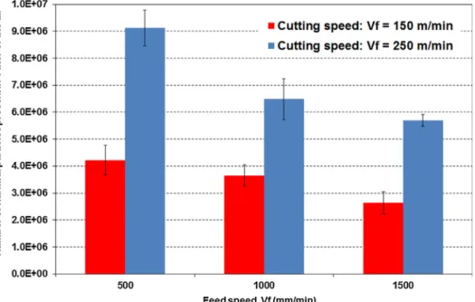
The evolution of average value of harmful particle numbers present in 1 L of the air with respect to the cutting parameters when using 2HF tool is presented inFig. 9. It can be seen that an increase in feed speed and a decrease in cutting speed leads to reduce the number of harmful particles. For instance, when trimming is conducted with cutting speed of 150 m/min, the variation of the feed speed from 500 mm/min to 1500 mm/min, favors the reduction by 37% of the average number of harmful particles. Same tendency is observed when trimming is con-ducted with a cutting speed of 250 m/min. For the influence of cutting speed, when feed speed of 500 mm/min is used and cutting speed varies from 250 m/min to 150 m/min, the number of harmful particles de-creases by 115%. The influence of feed speed on the number of harmful particles, as previously presented, can be explained by the fact that trimming with higher feed rate favors the increase of the chip thickness. As discussed previously, due to the higher chip thickness, the prob-ability of obtaining the settled particles on the machine table in the form of free fibers and fiber–matrix chunks mentioned increases (cf.
Fig. 8). Moreover, the influence of cutting speed is also directly related to the decrease of chip thickness. Indeed, when cutting speed increases, the chip thickness decreases as documented in literature[4,19,20]. In this stage, the cut chips are typically small; hence we get the higher probability of small size of chips which are easily emitted in the air because of light weight. Based on these results, it can be concluded that machining with lower cutting speed will generate smaller number of harmful particles. For this reason, in next phases of this study, only cutting speed of 150 m/min is considered.
3.2. Influence of helix angle on the number of harmful particles
TheFig. 10presents a comparison of the number of harmful parti-cles generated when using two geometries, twoflute helix tool (2HF) and two straightflute tool (2SF). It is to be noticed that these two tool geometries have similar number offlutes but different value of the helix angle (cf.Table 2). In order to eliminate the influence of cutting edge
modification (tool wear) on the number of harmful particles, only harmful particles generated in thefirst face of each cutting condition is considered (280 mm). It is evident that tool 2SF creates the highest harmful particles when compared with 2HF tool. In fact, at cutting condition of 1500 mm/min of feed speed, 150 m/min of cutting speed and 2 mm of radial of cut, the number of harmful particles resulting from the tool 2SF is higher than that of 2HF tools by 60%. This dif-ference in results can be explained be the fact that, high cutting forces
Fig. 5. Microscopic optical metrology system (Alicona InfiniteFocusSL) used for 3D profilometry analysis. (For interpretation of the references to colour in this figure legend, the reader is referred to the web version of this article.)
Fig. 6. Schematic view showing the machined area subjected to 3D topography characterization. With: (a) when the tool is considered new (after 0.05 m cutting distance) and (b) when the tool is con-sidered worn (after 1.63 m cutting distance).
are observed when trimming is conducted using a cutting tool with zero helix angle (compared to cutting tool with positive helix angle), espe-cially the radial component of the cutting force is high. This high radial force component leads to vibration of the tool during cutting. This vi-bration aids in crushing and disintegration of the CFRP chips into minute particles. Also, this tool vibration combined with fully engaged straight cutting edge poses an obstruction for evacuation of larger fi-ber–matrix fragments and disintegrate them into smaller particles. Hence, machining with cutting tool with zero helix angle leads to high dust emission. Conversely, when a tool with a positive helix angle is used, the radial force component is reduced in accordance with the helix angle, which in turn reduces the tool vibration. This decrease in vibration and gradual engagement of the tool with the workpiece evades crushing and disintegration of thefiber–matrix fragments and also aids in evacuation of these fragments through the helical flutes, there by leading to reduced dispersion of microchips in the air. Hence, it can be said that a helix angle of cutting edge effectively reduces the number of harmful particles dispersed in the air.
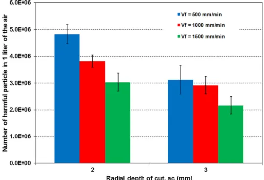
3.3. Influence of radial depth on the number of harmful particles As previously presented, in order to reduce the number of harmful particles, the combination of low cutting speed and high feed speed is necessary. Moreover, machining with cutting edge with helix angle also decreases the number of harmful particles. Additionally, the effect of depth of cut on the number of harmful particles should also be con-sidered. However, it is important to note that, there is no adequate evidence in literature on results on dust emission pertaining to radial
depth of cut. Nevertheless, research by Anirudh et al.[22]suggest that emission of harmful particles is reduced at low axial depth of cut. The
Fig. 11 presents the evolution of number of harmful particles as a function of radial depth of cut and feed speed. A net decrease in the number of harmful particles is observed for all the machining para-meters when radial depth of cut varies from 2 mm to 3 mm. More precisely, percentages of decrease for the feed speed of 500 mm/min, 1000 mm/min, and 1500 mm/min of the number of harmful particles are 35%, 24% and 29%, respectively when radial depth of cut in in-creased to 3 mm from 2 mm.
The results obtained on the influence of feed speed and radial depth of cut on the number of harmful particles can be explained by the fact that with high value of the depth of cut (e.g. superior to 2 mm), less particles in the air are observed and higher number offiber matrix fragments are seen settled on the machining table. At this high radial depth of cut, the equivalent chip thickness is also high, this creates large fiber–matrix fragments, owing to their higher mass, which are unable to disperse in the air and hence settle down on the machining table. Consequently, due to the higher chip thickness, the probability to ob-tain the settled particles on the machine table in the form of freefibers andfiber–matrix chunk increases, which is evident from the SEM image presented inFig. 12.
Given that, the increase in the chip thickness reduces the machining time and the harmful particles; this can have an adverse impact on the machining quality. Indeed, many studies have quantified the quality of the machined surface after trimming in function of the machining parameters[4,9,19,20]using“Sa” or “Ra” and more recently “crater volume” (Cv) as criteria. Therefore, in this study, the machining quality
Fig. 7. The total number of particles present in 1 L of the air classified based on particle sizes when machining with 2HF tool at the end of first face (0.28 m, when tool is considered as new) and with cutting speed (a) 150 m/min and (b) 250 m/min. (For interpretation of the references to colour in thisfigure legend, the reader is referred to the web version of this article.)
Fig. 8. Typical SEM images of collected particles generated by 2SF tool at cutting distance of 0.28 m for cutting speed of 150 m/min and radial depth of cut of 2 mm (a) Vf= 500 mm/min, (b) Vf= 1000 mm/min, (b) Vf= 1500 mm/min.
has been characterized by the roughness criterion “Sa” and “Cv” in
function of the machining parameters and the radial depth of cut. It is observed that values of surface roughness“Sa” increases with increasing
radial depth of cut (cf.Fig. 13) and the maximum value is observed for a radial depth of cut of 3 mm. The same trend is also observed inFig. 14
when considering the influence of the radial depth of cut on the values of Cv. These results can be confirmed by the topography images of
machined surface of specimens when trimming conducted with depth of cut of 2 mm and 3 mm which is illustrated inFig. 15. It is seen that in case of 3 mm of radial depth of cut, the higher level of machining da-mage in form of crater is visualized which is located in the area where plies are oriented at−45° compared to the cutting direction. For this reason, the values of Saand Cvmeasured in machined surface with
depth of cut 3 mm is superior to those when trimming conducted with depth of cut of 2 mm. This result can be explained by the fact that when the radial depth of cut increases the chip volume and also the maximum chip thickness increase. This phenomenon leads to rise in the cutting
forces which is responsible for the crushing of thefibers and hence, poor machining quality is obtained. Indeed, similar phenomenon has been observed when the feed speed increases. In fact, in the work of[9]
it was also clearly mentioned that the augmentation of the feed speed leads to increase of the average surface roughness“Ra” as well as the
crater volume“Cv”. It is important to mention that, from the work of [9,23,24]the Cvparameter is more recommended for characterization
of the machined surface when machining composites compared to Ra or Sacriteria. Based on the results presented in theFig. 12,Fig. 13and Fig. 14, it can be said that if we consider the surface quality as the main criteria (lowest surface roughness or volume crater), when trimming is conducted by the cutting tool 2SF, it is recommended to machine with a depth of cut of 2 mm. However, if we emphasize on reducing harmful particles, depth of cut of 3 mm should be adopted (lowest particles) when the same tool is used. In addition, industrially it is important to keep the surface quality (Saor Cv) as low as possible for the machined
component to be accepted in service[6,19].
Fig. 9. The evolution of harmful particle num-bers as a function of cutting speed and feed speed when machining with 2HF cutting tool and radial depth of cut of 2 mm after 1.68 m cutting distance (tool considered worn). (For interpretation of the references to colour in this figure legend, the reader is referred to the web version of this article.)
Fig. 10. The evolution of harmful particle numbers as a function of 2SF tool and 2HF tool for cutting speed of 150 m/min and radial depth of cut of 2 mm at cutting distance of 0.28 m. (For interpretation of the references to colour in thisfigure legend, the reader is referred to the web version of this article.)
3.4. Influence of grooves on the cutting edge on the number of harmful particles
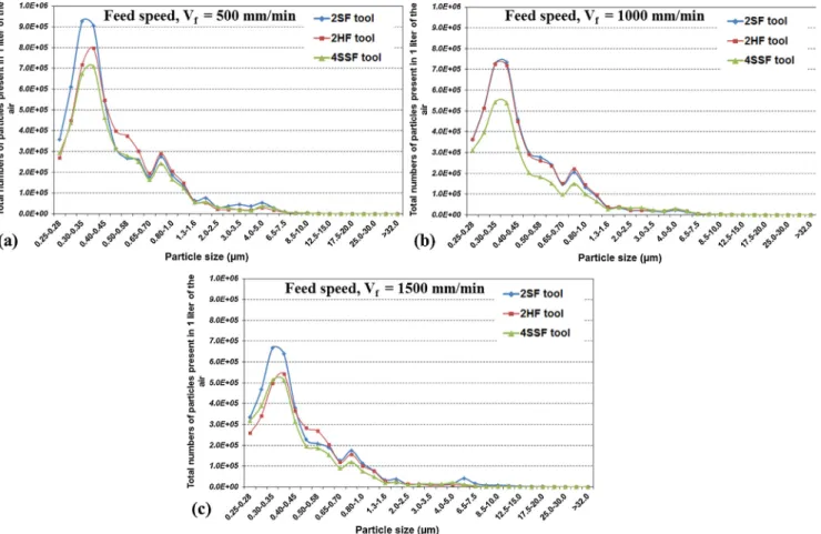
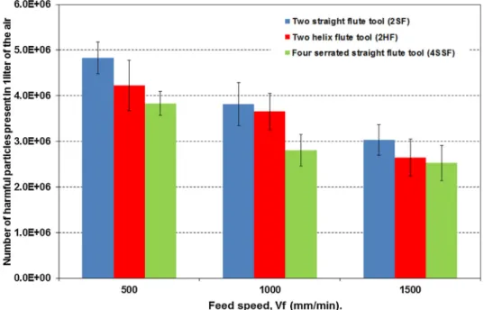
A new kind of cutting tool, four serrated straight flutes (4SSF), which have grooves along the cutting edge, is proposed in collaboration with ASAHI Company for machining composite materials (cf.Fig. 1). The Fig. 16illustrates the distribution of the number of the emitted particles in function of the particle size when trimming is conducted with a cutting speed of 150 m/min and different feed speeds and tool geometries. It is clear form this graphs that the particle number dis-tribution trend is similar for all the tools and for any condition of cutting selected. However, the least number of particles is always re-corded for the 4SSF tools. TheFig. 17presents the comparisons in terms of harmful particles which are generated by three tool geometries, e.g. 2SF, 2HF, and 4SSF. It is clearly seen that the tool 2SF creates the highest number of harmful particles when compared with other tool geometries, while tool 4SSF causes lowest number of harmful particles irrespective of cutting condition. In fact, at cutting condition of 500 mm/min and 150 m/min, the number of harmful particles resulting
from the tool 2SF is higher than those of tools 2HF and 4SSF by 14% and 26%, respectively. SEM observations of the cutting tool after trimming have been conducted to better understand this variation in the dust emission in function of the tool geometry. Indeed, fromFig. 18, which shows the obtained SEM images of cutting edges, we can clearly visualize that in case of tool 4SSF, there are more microchips adhering in the grooves along the cutting edge and the rake face (cf.Fig. 18a). However, limited adherence of microchips is observed in the case of 2HF and 2SF cutting tools (cf.Fig. 18b and c) compared to the 4SSF cutting tool. This phenomenon can be explained by the fact that, when machining is conducted with 4SSF tool which is characterized by 4 cutting edges with grooves the contact area between the active tool surface and CFRP workpiece is significantly higher compared to the other tools. In this case, the frictional phenomenon is more pronounced and the local temperature of machining can reach the glass transition temperature (Tg) of the matrix which favors the adhesion of the mi-crochips on the active surface of the tool as well as in the grooves. Similar phenomenon is observed in the work of Sheikh-Ahmad et al.
[25]and Haddad et al.[4,19], when trimming is conducted with burr
Fig. 11. Evolution of harmful particle numbers as a function of radial depth of cut with cutting speed of 150 m/min and cutting tool 2SF. (For interpretation of the references to colour in thisfigure legend, the reader is referred to the web version of this article.)
Fig. 12. Typical SEM images of collected particles machined by 2 SF tool at cutting distance of 0.28 m for cutting speed of 150 m/min and feed speed of 500 mm/min and radial depth of cut of (a) ac= 2 min, (b) ac= 3 min.
tool where the temperature of machining recorded in vicinity of the active surface of the tool (grooves) is superior to the Tgof the matrix
material in the CFRP. The same phenomenon of the dust adhesion to the cutting tool has been observed by Haddad et al.[19]when using burr tool. This phenomenon of adhering prevents the emission of particles during trimming. In addition, with the 4SSF tool, the obtained micro-chips are characterized mainly as a form offiber–matrix fragments as evident from the SEM images presented inFig. 19. Hence majority of the material removed using 4SSF tool ends up on the machine table, thereby reducing the quantity of harmful particles in air. Based on above results, it can be said that machining with higher feed speed and lower cutting speed will create minimum harmful particles, and this condition of machining is beneficial for the operators. This result is in good agreement with the results presented by Anirudh et al. [22].
However, if we refer to the literature, it is seen that, the increase in the feed speed and the decrease in the cutting speed, favors the degradation of the machining quality and increases the generation of the uncut fi-bers and the matrix degradation[4,20].
The influences of cutting speed and feed speed on the number of harmful particles observed in this study are in good agreement with those presented in the research work of Haddad et al. [19] when trimming is conducted with burr tools on the same composite material. It is important to notice that, all the above presented results are the average values of number of particles measured for 6 measurements taken during trimming of 6 faces of the 3 CFRP specimens which re-present a total cutting distance of 1.68 m. However, a significant de-viation is evident from the error bars presented in the graphs. This can be attributed to the phenomenon of tool wear which occurs during
Fig. 13. The evolution of surface roughness (Sa) as a function of radial depth of cut for cutting speed of 150 m/min of tool 2SF. (For interpretation of the references to
colour in thisfigure legend, the reader is referred to the web version of this article.)
Fig. 14. The evolution of crater volume (Cv) as a function of radial depth of cut for cutting speed of 150 m/min of tool 2SF. (For interpretation of the references to
machining of CFRP owing to their abrasive nature. Several authors have mentioned that, the dry machining favors the premature tool wear and has a significant impact on the cutting forces and on the mechanisms of chip formation. For this reasons, it is important to correlate the phe-nomenon of tool wear with the number of harmful particles.
3.5. Influence of tool wear on the number of harmful particles
TheFig. 20illustrates the evolution of harmful particle numbers as a
function of cutting distances when trimming is carried out with a cut-ting speed of 150 m/min and for the cutcut-ting tools 2HF, 2SF and 4SSF. It is important to mention that, each point on the graph represents the number of harmful particles measured after a distance of machining of 0.28 m (which corresponds to one face of the specimen). It is clearly noticed that the number of harmful particles measured decreases with increasing cutting distance. For example, when trimming is conducted with 2HF cutting tool and feed speed of 500 mm/min, the harmful particle number decreases by 28% after cutting of the six faces (which
Fig. 15. Topography of machined surface for 2SF tool with cutting speed of 150 m/min, feed speed of 500 mm/min, and cutting distance of 1.68 m (a) depth of cut of 2 mm, (b) depth of cut of 3 mm. (For interpretation of the references to colour in thisfigure legend, the reader is referred to the web version of this article.)
Fig. 16. The evolution of the total number of particles in function of the particles size as a function of different tool geometries when machining with cutting speed of 150 m/min, radial depth of cut of 2 mm, when tool is considered as new (cutting distance of 0.28 m) and with feed speed of (a) 500 mm/min, (b)1000 mm/min and (c) 1500 mm/min. (For interpretation of the references to colour in thisfigure legend, the reader is referred to the web version of this article.)
corresponds to the distance of cutting of 1.68 m) in comparison when cutting distance is equal to 0.28 m (end of the first face of the first coupon). The phenomenon of the reduction of the number of harmful particles, with increasing cutting distance, is observed for all cutting conditions regardless of tool geometries in this study. In fact, with the increase of the cutting distance, for any tool used, the radius of cutting
edges increases as observed in theFigs. 21 and 22. In this case, the value of the cutting edge radius becomes more prominent compared to the carbonfiber diameter (≈7 µm), which favors the increase of the cutting forces. Consequently, the mechanisms of chip formation are due to the fracture induced by combination of bending and local buckling unlike shear mechanisms observed when using a new tool (with cutting
Fig. 17. The evolution of harmful particle numbers as a function of tool geometries for cutting speed of 150 m/min and radial depth of cut of 2 mm. (For inter-pretation of the references to colour in thisfigure legend, the reader is referred to the web version of this article.)
Fig. 18. SEM image showing embedded microchips in the serrations and rake face for cutting condition of 150 m/min cutting speed, 500 mm/min feed speed and 2 mm of depth of cut with (a) 4SSF cutting tool, (b) 2HF cutting tool and (c) 2SF cutting tool.
Fig. 19. SEM images of particles collected after a cutting distance of 0.28 m with cutting speed of 150 m/min, feed speed of 500 mm/min and radial depth of cut of 2 mm with (a) 2SF cutting tool, (b) 2HF cutting tool and (c) 4SSF cutting tool.
edge radius≈3 µm). For higher value of the cutting edge radius, the probability to obtain chips in the form of freefibers and fiber-matrix chunk is more prominent.
Finally, the chips generated are in the form of fragments that cor-respond to larger size of particles and, due to their heavier weight, they quickly drop on to the machining platform. From this analysis of harmful particles, it can be said that the number of harmful particles can be reduced if trimming process is conducted at higher feed speed, lower cutting speed and higher depth of cut. However, as mentioned earlier, this combination can give rougher machined surface which is also documented in [4,20]. Finally, for the optimization of the ma-chining parameters in conventional process, it will be crucial to strike a balance between machining quality and the number of harmful parti-cles released. For this reason, the roughness of the machined surface has been investigated in function of the tool geometry and the cutting distance covered by the tools. In this context, the newly proposed tool
geometry (4SSF) generates minimum number of harmful particles when compared to the classical tool geometries (2SF and 2HF). Therefore, in order to estimate the ability of this tool in term of reduction of harmful particles and acceptable machining quality, a comparison in term of surface quality (Saand Cv) of specimens trimmed by three used tool
geometries is considered. In fact, the evolution of cutting parameters as a function of surface roughness (Sa) and crater volume (Cv) is presented
inFigs. 23 and 24respectively. It can be seen fromFig. 23 that the surface roughness (Sa) resulting from the 4SSF tool is superior to those
obtained from other tools regardless of cutting parameters. This can be attributed to the formation of streaks due to the presence of grooves along cutting edge of the 4SSF tool (cf.Fig. 25).
However, if the quantification of machining quality is characterized using Cv (as recommended for composite materials by recent
re-searchers[9,23,24]) criterion, the tendency is different from that ob-served inFig. 23. Indeed, inFig. 24except for feed speed of 500 mm/
Fig. 20. Evolution of the harmful particle numbers generated using 2SF, 2HF and 4SSF cutters as a function of cutting distance for radial depth of cut of 2 mm and cutting speed of 150 m/min. (For interpretation of the references to colour in thisfigure legend, the reader is referred to the web version of this article.)
Fig. 21. SEM images of cutting edges of tool 4SSF(a) unused tool, (b) magnified view of unused tool, (c) magnified view of cutting edge for cutting speed of 150 m/min and feed speed of 500 mm/min after cutting distance of 1.68 m, (d) cartography after a cutting distance of 1.68 m. (For interpreta-tion of the references to colour in thisfigure legend, the reader is referred to the web version of this article.)
min, we can see that values of Cvof specimens resulting from 4SSF tool
is lower than those of specimens obtained by other tool geometries (2SF tool and 2HF tool), suggesting that a better machining quality is ob-tained when 4SSF tool is used. This difference in results inFigs. 23 and 24can be attributed to the principle of Cvcalculation where only the
machining damage (volume of craters and cavities below the mean surface) is considered. In addition, Sais the average height of the
sur-face which includes measurement of both peaks and craters whereas in Cvmeasurements only craters are considered. On the contrary, an
ex-ception in case of feed speed of 500 mm/min can be seen where Cv
value is high. It is due to the fact that, at low feed speed the value of theoretical chip thickness is small, as this value of chip thickness is smaller than the depth of grooves present on the cutting edges, the impact of grooves creates a significantly deep groove, which can be seen declining with increase in feed speed (cf.Fig. 25). Hence, the grove geometry (height and the direction of grooves) should be optimized in
order to reduce the influence of grooves on the machined surface quality. These results show that the newly proposed tool geometry (4SSF) exhibits promising results in minimize the harmful particles and also improves machining quality.
4. Conclusions
The experimental study on the dust analysis in terms of number of particles released during trimming of multidirectional CFRP composites using PCD tool is elaborated in this research work. The studies on the influence of cutting parameters (cutting speed, feed speed, and depth of cut), tool geometries, and tool wear in terms of cutting distance, were conducted. The following critical conclusions can be drawn from the study:
•
The SEM imaging analysis conducted on the collected dust, haveFig. 22. SEM images of cutting edges of tool 2HF (a) unused tool, (b) magnified view of unused tool, (c) magnified view of cutting edge for cutting speed of 150 m/min and feed speed of 500 mm/min after cutting distance of 1.68 m, (d) Cartography after machining distance of 1.68 m. (For inter-pretation of the references to colour in this figure legend, the reader is referred to the web version of this article.)
Fig. 23. Evolution of surface roughness (Sa) as a function of cutting parameters for three tool geometries with cutting speed of 150 m/min. (For interpretation of the
Fig. 24. Evolution of crater volume (Cv) as a function of cutting parameters for three tool geometries with cutting speed of 150 m/min. (For interpretation of the
references to colour in thisfigure legend, the reader is referred to the web version of this article.)
Fig. 25. Topography of machined surface with cutting speed of 150 m/min for 4SSF tool, depth of cut of 2 mm, and cutting distance of 0.055 m (a) feed speed of 500 mm/min, (b) feed speed of 1000 mm/min (c) feed speed of 1500 mm/min. (For interpretation of the references to colour in thisfigure legend, the reader is referred to the web version of this article.)
revealed the presence of three main forms of chips viz.fine powder (matrix andfibers mixture), free fibers and fragment of fiber-matrix chunks.
•
The increase of the feed speed and decrease of cutting speed favors the reduction of the number of harmful particles in the air and in-creases the formation of the chips in the form offiber-matrix chunk. The number of harmful particles decreases when radial depth of cut increases from 2 mm to 3 mm.•
The number of harmful particles is significantly affected by tool geometries, where tool 2SF generates the maximum number of harmful particles, which are followed by those resulting from tools 2HF and 4SSF. However, when trimming is conducted with the proposed new tool (4SSF), the presence of the grooves along the cutting edges, promotes the adhesion of the particles in the cavity and reduces the dispersion of the particles in the air. Consequently, these particles are not emitted in the air, thereby reducing the presence of the harmful particles in the air.•
An increase of cutting distance also favors the reduction of number of harmful particles as longer cutting distance favors the mechan-isms of chip formation by combination of bending and local buck-ling unlike shear mechanisms observed for the new tool (with cut-ting edge radius≈3 µm). For higher value of the cutting edge radius the probability of obtaining chips in the form of freefibers and fiber-matrix chunk is more prominent. Finally, rougher chips are created corresponding to lager size of particles and, due to their heavier weight, they quickly drop on the machining platform.•
The new 4SSF tool was effective in reducing the emission of harmful particles and also preserving acceptable surface quality. However, further optimization of the tool, most importantly the grove geo-metry need to be optimized for eliminating the streaks formed on the machined surface (at low feed speeds) and also to improve the machining quality.CRediT authorship contribution statement
N. Nguyen-Dinh: Formal analysis, Investigation, Writing - original draft. A. Hejjaji: Methodology, Validation, Formal analysis, Investigation, Writing - original draft, Writing - review & editing, Visualization.R. Zitoune: Conceptualization, Resources, Data curation, Writing - review & editing Supervision. C. Bouvet: Validation, Resources, Supervision.M. Salem: Methodology, Investigation. Declaration of Competing Interest
The authors declare that they have no known competingfinancial interests or personal relationships that could have appeared to influ-ence the work reported in this paper.
Acknowledgments
The authors wish to thank ASAHI Company (France) for their technical support.
References
[1] Zitoune R, Krishnaraj V, Sofiane Almabouacif B, Collombet F, Sima M, Jolin A. Influence of machining parameters and new nano-coated tool on drilling perfor-mance of CFRP/Aluminium sandwich. Compos Part B Eng 2012;43:1480–8.https://
doi.org/10.1016/J.COMPOSITESB.2011.08.054.
[2] Cadorin N, Zitoune R, Seitier P, Collombet F. Analysis of damage mechanism and tool wear while drilling of 3D woven composite materials using internal and ex-ternal cuttingfluid. J Compos Mater 2015;49:2687–703.https://doi.org/10.1177/ 0021998314553045.
[3] Hejjaji A, Singh D, Kubher S, Kalyanasundaram D, Gururaja S. Machining damage in FRPs: Laser versus conventional drilling. Compos Part A Appl Sci Manuf 2016;82:42–52.https://doi.org/10.1016/J.COMPOSITESA.2015.11.036. [4] Haddad M, Zitoune R, Eyma F, Castanié B. Machinability and surface quality during
high speed trimming of multi directional CFRP. Int J Mach Mach Mater 2013.
https://doi.org/10.1504/IJMMM.2013.053229.
[5] Prakash R, Krishnaraj V, Zitoune R, Sheikh-Ahmad J. High-speed edge trimming of CFRP and online monitoring of performance of router tools using acoustic emission. Mater (Basel, Switzerland) 2016;9.https://doi.org/10.3390/ma9100798. [6] Slamani M, Chatelain J-F, Hamedanianpour H. Influence of machining parameters
on surface quality during high speed edge trimming of carbonfiber reinforced polymers. Int J Mater Form 2018.https://doi.org/10.1007/s12289-018-1419-2. [7] Wang H, Sun J, Zhang D, Guo K, Li J. The effect of cutting temperature in milling of
carbonfiber reinforced polymer composites. Compos Part A Appl Sci Manuf 2016;91:380–7.https://doi.org/10.1016/J.COMPOSITESA.2016.10.025. [8] Wang F, Yin J, Jia Z, Niu B, Liu W. A novel approach to evaluate the delamination
extent after edge trimming of carbon-fiber-reinforced composites. Proc Inst Mech Eng Part B J Eng Manuf 2017.https://doi.org/10.1177/0954405417699015. 095440541769901.
[9] Nguyen-dinh N, Zitoune R, Bouvet C, Leroux S. Surface integrity while trimming of composite structures : X-ray tomography analysis. Compos Struct 2019;210:735–46.
https://doi.org/10.1016/j.compstruct.2018.12.006.
[10] Wang DH, Ramulu M, Arola D. Orthogonal cutting mechanisms of graphite/epoxy composite. Part I: unidirectional laminate. Int J Mach Tools Manuf 1995.https:// doi.org/10.1016/0890-6955(95)00014-O.
[11] Zitoune R, Collombet F, Lachaud F, Piquet R, Pasquet P. Experiment–calculation comparison of the cutting conditions representative of the longfiber composite drilling phase. Compos Sci Technol 2005;65:455–66.https://doi.org/10.1016/J. COMPSCITECH.2004.09.028.
[12] Koplev A, Lystrup A, Vorm T. The cutting process, chips, and cutting forces in machining CFRP. Composites 1983;14:371–6. https://doi.org/10.1016/0010-4361(83)90157-X.
[13] Wang DH, Ramulu M, Arola D. Orthogonal cutting mechanisms of graphite/epoxy composite. Part II: multi-directional laminate. Int J Mach Tools Manuf
1995;35(12):1639–48.https://doi.org/10.1016/0890-6955(95)00015-P. [14] Ramulu M, Kramlich J. Machining offiber reinforced composites: Review of
en-vironmental and health effects. Int J Environ Conscious Des Manuf 2004;11:1–19. [15] Standardization EC for. Workplace atmospheres— Sizefraction definitions for
measurement of airborne particles. Br Stand 1993:1–15.
[16] Wagman J. Dusts and residues from machining and incinerating graphite/epoxy composites: a preliminary study. Environ Technol Lett 1982;3:469–78.https://doi. org/10.1080/09593338209384151.
[17] Boatman ES, Covert D, Kalman D, Luchtel D, Omenn GS. Physical, morphological, and chemical studies of dusts derived from the machining of composite-epoxy materials. Environ Res 1988;45:242–55.https://doi.org/10.1016/S0013-9351(88) 80050-1.
[18] Miller JL, Tuttle M. Investigation of machinability and dust emissions in edge trimming of laminated carbonfiber. Composites 2014.
[19] Haddad M, Zitoune R, Eyma F, Castanie B. Study of the surface defects and dust generated during trimming of CFRP: Influence of tool geometry, machining para-meters and cutting speed range. Compos Part A Appl Sci Manuf 2014.https://doi. org/10.1016/j.compositesa.2014.07.005.
[20] Sheikh-Ahmad JY. Machining Polym Compos 2009. https://doi.org/10.1007/978-0-387-68619-6.
[21] Klocke, F., C. Koenig, C. Wuertz and CD. Environmental Effects and Safety in Machining Fibrous Composites.pdf. In: S. Jahanmir, M. Ramulu and PK, editor., Inc., New York: 1999, p. 411–25.
[22] Iyer AK. Characterization of composite dust generated during milling of uni-di-rectional and randomfiber. Composites 2015.
[23] Hejjaji A, Zitoune R, Crouzeix L, Collombet F. Influence of controlled depth abrasive water jet milling on the fatigue behavior of carbon/epoxy composites. Compos. Part A: Appl. Sci. Manufact. 2019;121:397–410.https://doi.org/10.1016/j.compositesa. 2019.03.045.
[24] Hejjaji A, Zitoune R, Crouzeix L, Le S, Collombet F. Surface and machining induced damage characterization of abrasive water jet milled carbon/epoxy composite specimens and their impact on tensile behavior. Wear 2017;376–377:1356–64.
https://doi.org/10.1016/j.wear.2017.02.024.
[25] Sheikh-Ahmad JY, Almaskari F, Hafeez F. Thermal aspects in machining CFRPs: effect of cutter type and cutting parameters. Int J Adv Manuf Technol 2019;100:2569–82.https://doi.org/10.1007/s00170-018-2881-1.