Open Archive TOULOUSE Archive Ouverte (OATAO)
OATAO is an open access repository that collects the work of Toulouse researchers and
makes it freely available over the web where possible.
This is an author-deposited version published in :
http://oatao.univ-toulouse.fr/
Eprints ID : 15676
To link to this article :
DOI:10.1016/j.combustflame.2016.01.004
URL :
http://dx.doi.org/10.1016/j.combustflame.2016.01.004
To cite this version :
Mari, Raphaël and Cuenot, Bénédicte and Rocchi, Jean-Philippe and
Selle, Laurent and Duchaine, Florent Effect of pressure on
Hydrogen/Oxygen coupled flame-wall interaction. (2016)
Combustion and Flame, vol. 168. pp. 409-419. ISSN 0010-2180
Any correspondence concerning this service should be sent to the repository
administrator:
[email protected]
Effect
of
pressure
on
hydrogen/oxygen
coupled
flame–wall
interaction
Raphael
Mari
a,∗,
Benedicte
Cuenot
a,
Jean-Philippe
Rocchi
a,
Laurent
Selle
b,
Florent
Duchaine
aa CERFACS, 42 av G. Coriolis, 31057 Toulouse, France b CNRS, IMFT, F-31400 Toulouse, France
Keywords:
Real-gas thermodynamics Flame–wall interaction Conjugate heat transfer
a
b
s
t
r
a
c
t
Thedesign and optimizationofliquid-fuelrocketenginesis amajorscientific and technological chal-lenge.Oneparticularly criticalissueisthe heatingofsolidpartsthat aresubjectedtoextremely high
heatfluxes whenexposed tothe flame. Thisinturn changesthe injector liptemperature, leading to
possiblydifferentflamebehaviorsandafullycoupledsystem.Asthechamberpressureisusuallymuch largerthanthecriticalpressureofthemixture,supercriticalflowbehaviorsaddevenmorecomplexity
tothethermalproblem.Whensimulatingsuchphenomena,thesethermodynamicconditionsraiseboth
modelingandnumericalspecificissues.Inthispaper,bothsubcriticalandsupercriticalhydrogen/oxygen one-dimensional,laminarflamesinteractingwithsolidwallsarestudiedbyuseofconjugateheattransfer simulations,allowingtoevaluatethewallheatfluxand temperature,theirimpactontheflameaswell astheirsensitivitytohighpressureandrealgasthermodynamicsupto100barwhererealgaseffects
areimportant.Atlow pressure,resultsare foundingoodagreementwithpreviousstudiesintermsof
wallheatfluxand quenchingdistance,and thewallstaysclosetoisothermal.Onthecontrary,dueto importantchangesofthefluidtransportpropertiesandthe flamecharacteristics,the wallexperiences significantheatingathighpressureconditionandtheflamebehaviorismodified.
1. Introduction
Mostofhighperformancepropulsion devicessuch asturbines, rocket engines or scramjets operate in wall-bounded flows. The interaction betweenflame andwalls hasa direct andstrong im-pact on combustion, pollutant emissions and combustion cham-berlifetime. Understandingthemechanismsatplayinflame–wall interaction (FWI) is therefore necessary to further gain in per-formance, safety,fuel consumption andunburnt gasemission. As shown in [1,2], local FWI may be described in simple laminar flowswheregenericflameconfigurationsmaybeintroduced. Dur-ingtheflame–wallinteractionprocess,theflamespeedand thick-ness decrease,beforefull quenchingata few microns awayfrom the wall. When the flame approaches the wall, the temperature decreases fromburnt gases (approximately 3000 Kfor hydrogen (H2)/oxygen(O2)flamesat1bar)towalllevelsthataremaintained
in the 300–800 K range to avoid damaging. This high tempera-turevariation occursina very thinlayer,lessthan 1mm, leading toverystrongtemperaturegradientsandmakingexperimental ob-servationofFWIquitedifficult.
∗ Corresponding author.
E-mail address: [email protected] (R. Mari).
Ezekoye et al. [3] experimentally studied the impact of wall temperature and the equivalence ratio on the wall heat flux for propane and methane flames. It was shown that the maximum wall heatflux decreaseswhen thewalltemperatureincreases.Lu et al. [4]investigated FWI in the side wall quenching configura-tion where the flame propagates along the wall and found that the ratioofthewall heat fluxto theheat releaseintheflame is roughlyconstantandequalto0.3–0.4.Basedonexperimental cor-relations, Boustetal.[5]proposed a theoreticalrelation between the normalized wall heat flux andthe quenching Pecletnumber, defined astheflame positionnormalized by theflame thickness, formethane-airflameswheretheyobservethatthewallheatflux isinverselyproportionaltotheflamequenchingdistance.
Many numerical studies have been conducted on laminar flame–wall interactions [6–10]. It has been shown by Popp et al. [9] that in the low wall temperature regime (300 K <
Tw < 400 K) the wall can be assumed chemically inert. Kim et al.[11] experimentallyconfirmed thisresultusingseveral sur-face materials andwall temperatures. Dabireauet al.[7], Gruber et al.[12] andOwstonetal.[10],demonstrateda strongly differ-entbehaviorforhydrogenflamescomparedtohydrocarbonflames. Hydrogen flame quenching occurs much closer to the wall rela-tively to the flame thickness. Normalized wall heat flux is also largelydifferentfromhydrocarbonflamesandequalto∼0.12.
Nomenclature
Symbol Units Description
Cp J K −1 kg −1 Heat capacity
Dth m 2 s −1 Thermal diffusivity
e J m −2 K −1 s −1/2 Effusivity
Pc Pa Critical pressure
Pe – Peclet number based on heat release rate PeF – Peclet number based on fuel consumption rate
Q W m −3 Heat release rate
Q∗ – Heat release rate non-dimensionalized with Q 0 l /δ
Q0
l W m −2 Laminar flame power
S0
l m s −1 Flame speed
Sc – Schmidt number
Tc K Critical temperature
TS K Solid temperature
Tw K Fluid-solid interface temperature
Z – Compressiblity factor
Greek symbols
δl m Thermal flame thickness
δ m Diffusive flame thickness
1H J kg −1 Heat per kg of fuel
κ – Ratio of wall and fluid effusivities
λ W m −1 K −1 Thermal conductivity
8w W m −2 Heat flux
8∗
w – Heat flux non-dimensionalized with Q l0
τ s Flame characteristic time
Superscripts
IF F Infinitely Fast Flame
C Coupled U Uncoupled b burnt u unburnt Subscripts Q quenching w wall
Inallthesestudies,resultshavebeenprovidedforwall bound-ary conditions either adiabatic or isothermal. However in reality heattransferoccurringbetweenthesolidwallandthefluidresults inapossibleincreaseofwalltemperatureandanon-zeroheatflux, i.e. neitherisothermalnoradiabaticwallbehavior.Inaddition,the wall temperatureisusually unknownandintroduces asignificant uncertainty onthe predictedheatflux. Finally,FWI beinga tran-sientphenomenon,eventuallyleading toflamequenching,the so-lution cannotbe searchedforasa steadystatesolution and sim-ulations describing the unsteady coupling of heat conduction in the wall withfluid dynamicsandheat transfer arerequired [13]. Such approachavoids toimposethe walltemperatureatan arbi-traryvalue,andallowsittoadapttothevaryingfluidtemperature, consequentlysignificantlymodifyingthewallheatflux.
Toaddressthisissue,thepresentstudyconsiderstheunsteady behavior of a stoichiometric laminar one-dimensional premixed hydrogen–oxygenflameimpingingonacoldwallincluding conju-gateheattransfer.Thecontextisliquid-fuelrocketengines(LREs), which operateat verylow temperature andhighpressurewhere thethermodynamicpropertiesdepartfromidealgaslaws.Indeed, beyondthecriticalpoint,definedby(Pc,Tc)valuesspecifictoeach species, surface tension disappears and the distinction between gaseous andliquid phasesvanishes.This stateof matteris called supercritical, wherephasechangeisreplaced byasteep but con-tinuous variation of the density and thermodynamic properties. Therefore the objective of the study istwofold: first, the role of conjugate heat transfer inFWI is studied; second, theimpact on FWIofhighpressure,uptosupercriticalconditions,isevaluated.
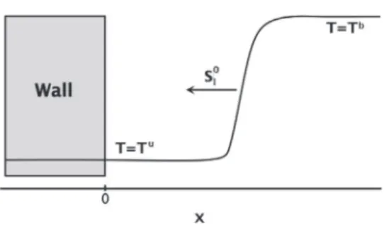
As shown in Fig. 1, the chosen configuration corresponds to head-on quenching (HOQ), where the flame propagates towards the wall with the characteristics of a free flame before interact-ingwiththewall.Inthissimplifiedconfigurationin-depthanalysis canbemadeandagoodunderstandingofbasicphenomenacanbe achieved. TheHOQconfigurationappearsasanecessaryfirststep
Fig. 1. Flame–wall interaction (FWI): head-on quenching (HOQ) configuration. Ini- tial wall temperature T i
w is set equal to fresh gas temperature T u .
tostudyboth effectsofhighpressureandconjugateheat transfer priortothethermalstudyofrealisticconfigurations.
2. Numericalsetupandmethodology
Simulationswereperformedbyrunningsimultaneouslyafluid (AVBP) and a thermal (AVTP) solver in a coupled framework. Forcomparisonpurposes,uncoupled simulationswithan isother-mal wall were also computed. In AVBP, the compressible re-active Navier–Stokes equations are solved with a third order in space and fourth order in time, two-steps Taylor–Galerkin scheme [14,15] along with a second order Galerkin scheme for diffusion terms.The parallel conductionsolver AVTP is based on thesame datastructure thanAVBP andalsouses a second order Galerkindiffusion scheme. Timeintegration is done with an im-plicitfirst orderforward Eulerscheme.The resolutionofthe im-plicitsystemisdonewithaparallelmatrixfreeconjugategradient method.
Thecouplingmethodologyconsistsinan exchangeofvariables at the wall surface between both codes: the fluid solver sends a heat flux and the heat conduction code sends back a temper-ature. Data are exchanged through a supervisor using OpenPalm libraries [16]. Between two coupling events, the flow and wall thermalconductionare advancedintime by aquantity
α
fτ
f andα
wτ
w respectively, whereτ
f andτ
w are the flow andheat con-duction characteristictimes.To respect simultaneity,the physical timecomputedbythecodesmustbethesamebetweentwodata exchanges:α
fτ
f=α
wτ
w.Thisensures continuityoftheheatflux andtemperatureatthewallsurface.Moredetailsandvalidationof thecouplingmethodologycanbefoundin[17].Computationswererun onuniformgrids,ofsimilargrid spac-ing(seeTable4),inboththefluidandthesolid.Theywere initial-ized witha free stationarypremixed flame previously calculated underthesamethermodynamic conditions(pressure and temper-ature),andlocatedfarenoughfromthewalltoassumeno interac-tionatthestartofthesimulation.Forthesamereasontheinitial walltemperatureTi
w wastakenequaltothefreshgastemperature
Tu. The fluid boundary condition at the open endis a pressure-imposedoutlet,usingthecharacteristicformulationfor compress-ibleflow[18].Thetemperatureisimposedattheleftsolid bound-arytotheinitialwalltemperatureTi
w.Thesolidissufficientlylong toensurethatthisboundaryconditiondoesnotinfluenceFWI.
3. Chemicalkinetics
Computationswerecarriedoutwitha purehydrogen(H2)and
pureoxygen(O2)mixtureatstoichiometry.Thecombustionof
hy-drogen and oxygen is modeled using a skeletal mechanism ac-countingfor8speciesand12reactionsfromBoivinetal.[19], re-portedinTable1.Itisderivedfromthe21-stepSanDiegodetailed mechanism[20],usedinmanyhydrogencombustionapplications. The so-called San Diego scheme has demonstrated its ability to
Fig. 2. 1D flame profiles of (a) temperature T , (b) heat release rate Q , (c) HO 2 and (d) H mass fractions for (–) San Diego [20] and (- -) Boivin [19] mechanisms. Case 2a:
pressure is 1 bar and fresh gas temperature 300 K.
Table 1
Rate coefficients in Arrhenius form k = AT n exp (
−E/R 0 T ) as in [19] . Reaction Aa n Ea R1 H + O 2 ⇌ OH + O kf 3.52 10 16 −0 .7 71 .42 kb 7.04 10 13 −0 .26 0 .60 R2 H 2 + O ⇌ OH + H kf 5.06 10 4 2 .67 26 .32 kb 3.03 10 4 2 .63 20 .23 R3 H 2 + OH ⇌ H 2 O + H kf 1.17 10 9 1 .3 15 .21 kb 1.28 10 10 1 .19 78 .25 R4 H + O 2 + M → HO 2 + M b k0 5.75 10 19 −1 .4 0 .0 k∞ 4.65 10 12 0 .44 0 .0 R5 HO 2 + H → 2 OH 7.08 10 13 0 .0 1 .23 R6 HO 2 + OH ⇌ H 2 + O 2 kf 1.66 10 13 0 .0 3 .44 kb 2.69 10 12 0 .36 231 .86 R7 HO 2 + OH → H 2 O + O 2 2.89 10 13 0 .0 −2 .08 R8 H + OH + M ⇌ H 2 O + M c kf 4.00 10 22 −2 .0 0 .0 kb 1.03 10 23 −1 .75 496 .14 R9 2 H + M ⇌ H 2 + M c kf 1.30 10 18 −1 .0 0 .0 kb 3.04 10 17 −0 .65 433 .09 R10 2 HO 2 → H 2 O 2 + O 2 3.02 10 12 0 .0 5 .8 R11 HO 2 + H 2 → H 2 O 2 + H 1.62 10 11 0 .61 100 .14 R12 H 2 O 2 + M → 2 OH + M d k0 8.15 10 23 −1 .9 207 .62 k∞ 2.62 10 19 −1 .39 214 .74 a Units are mol, s, cm 3 , kJ and K.
b Chaperon efficiencies H
2 : 2.5, H 2 O: 16.0, 1.0 for all other species. Troe falloff
with F c = 0 . 5 .
c Chaperon efficiencies H
2 : 2.5, H 2 O: 12.0, 1.0 for all other species. d Chaperon efficiencies H
2 : 2.5, H 2 O: 6.0, 1.0 for all other species. Troe falloff
with F c = 0 . 265 exp (−T / 94) + 0 . 735 exp (−T / 1756) + exp (−T / 5182) .
predictpremixedflamespeed,autoignitiondelay,burntgases tem-peratureandextinctionlimitsundermanyconditionsofpressure, temperatureandcomposition[21]andisconsideredasareference. InordertovalidateBoivin’sschemeinthethermodynamic condi-tionsofinterest,i.e.,freshgasat150K,300Kand750Kand
pres-sure up to 100 bar, premixed flames have been computedusing CANTERA[22]andcomparedwiththedetailedmechanism.Results are shown here forflames corresponding to Cases 2a and 2c of
Table3.Thestoichiometriclaminarflamespeedsobtainedwiththe Boivin scheme(10.76ms−1 and9.03ms−1, respectively)are very
close to the values computed with the reference scheme of San Diego (10.61ms−1 and9.46ms−1, respectively). Theflame
struc-tures shownin Figs. 2and 3demonstratethat both mechanisms are inverygoodagreementintermsoftemperature,heat release rate, andspecies(includingradicals)massfractionprofiles,atlow andhighpressure.Inparticular,thegoodpredictionofspecieslike HO2 is criticalforFWI,aswillbe seenlater. Similar resultswere
obtainedfortheothercasesconditions.
4. Real-gasequations
For high pressure computations, real-gas thermodynamics are accounted for through the Peng–Robinson equation of state [23] (PR-EOS).Thegeneralformofacubicequation ofstate isgivenby:
P
(
v
,T)
= RTv
− b−a
(
T)
(
v
+δ
1b)(
v
+δ
2b)
(1)where P is the pressure, T the temperature, v the molar vol-ume andR theperfect-gasconstant. The coefficientsa andb ac-count respectivelyforlong-rangeandshort-rangeinteractions be-tween molecules.In the Peng–Robinson equation the parameters (
δ
1,δ
2)are(
1+√2,1−√2)
.Allthermodynamiccoefficientsmustbemodifiedtotakeintoaccountrealgaseffects.Atlowpressure,a standard technique consistsintabulatingorusingpolynomial fits to allow for the temperaturedependence.This procedure can be
Fig. 3. 1D flame profiles of (a) temperature T , (b) heat release rate Q , (c) HO 2 and (d) H mass fractions for (–) San Diego [20] and (- -) Boivin [19] mechanisms. Case 2c:
pressure is 100 bar and fresh gas temperature 300 K.
Table 2
Species critical-point temperature T c and pressure P c , and Schmidt numbers.
Parameters H 2 O 2 H 2 O O H OH H 2 O 2 HO 2
Tc [K] 33 154 .6 647 .1 105 .3 190 .8 105 .3 141 .3 141 .3
Pc [bar] 12 .6 49 .7 217 .7 70 .0 306 .0 70 .0 47 .3 47 .3
Sc 0 .28 0 .99 0 .77 0 .64 0 .17 0 .65 0 .65 0 .65
extended toaccountforpressuredependencebykeepingthe tab-ulation forlow pressurereferencevaluesandusedeparture func-tions basedontheEOStocomputetheinfluenceofpressure[24]. For example to calculate the constant-pressure heat capacity Cp, onestartstowritetheGibbsfunctionGas:
G
(
P,T)
=G0+Pv
− RT+Z v0
v
P
(
v
¯,T)
dv
¯ (2)wherev0 andG0arerespectivelythemolarvolumeandtheGibbs
energyatareference low pressure.Theenthalpyhisthen classi-callydefinedas:
h=G− T
µ ∂
∂
GT
P
(3) aswellastheconstant-pressureheatcapacity:
Cp=
µ ∂
h∂
T
P (4) Thispointsoutthatlow-pressuredata,combinedwiththePR-EOS, allowtocomputeallthermodynamicpropertiesofthefluidathigh pressure.The viscosity and thermal conductivity are modeled follow-ing the method of Chung [25], based on the theory of corre-sponding states, linking low- and high-pressure values through semi-empirical functions expressedin reduced variablesT/Tc and
P/Pc.The low-pressure (ideal gas) reference values are computed from the Chapman–Enskog equation. Species diffusion velocities are expressed as functions of the species gradients using the Hirschfelder–Curtisapproximation andconstant Schmidtnumbers
Sc.Itwasindeedverifiedwithdetailedcalculationsusingthe soft-ware CANTERA [22], that in the considered cases the Schmidt numbersofmostspeciesdonot stronglyvarythrough theflame, andtake thevaluesreportedinTable 2.Soret andDufoureffects arenotincluded.
The criticalpoint coordinates of theintermediate speciesOH, O, H, H2O2, HO2 (for which no experimental values are
avail-able)are estimatedasin[26],usingtheLennard–Jones potential-welldepth,andthemolecular diameter,takenfromthetransport databaseoftheSanDiegomechanism[20].
The ability of the AVBP solver to accurately reproduce super-criticalandtranscriticalflows andflames hasbeen demonstrated invarious configurationscorresponding toLRE conditions[27,28]. Notethatreal-gasthermodynamicsalsohaveanimpactonthe for-mulationofboundaryconditionsandJacobianmatricesofthe nu-mericalschemes.
5. Flamewallinteraction(FWI)
Flame–wallinteractionisfirstcharacterizedwiththewallheat flux,definedastheconductivefluxevaluatedatthewall:
8
w=λ
w∂
T∂
x¯
¯
¯
¯
w (5) whereλ
w isthethermalconductivityofthefluidevaluatedatthe wall.Thewallheatfluxisstronlgylinkedtotheflame characteris-tics:thethermalflamethicknessδ
l iscalculatedfromthe temper-aturegradient:δ
l=Tb− Tu
(
∇
T)
max(6) where(
∇
T)max isthemaximumofthetemperaturegradient.This flamethicknessmaybealsoestimatedfromtheflameparameters usingthediffusiveflamethicknessδ
[7]givenby:δ
=λ
u
ρ
uCu pSl0(7) whereSl0isthelaminarflamespeed.ThelaminarflamepowerQl0
isdefinedas:
Ql0=
ρ
uYuFS0l
1
H (8)where Yu
F is the fuel mass fraction in unburnt gases and
1
H[Jkg−1]theheatproducedperkilogramoffuelconsumed.The wallheatflux isnon-dimensionalizedby theflamepower as
8
∗w=
8
w/Ql0,whereasthenon-dimensionalflameheatrelease rateisQ∗=Qδ
/Q0l.Inaddition,the flamecharacteristictime
τ
=δ
/S0l is used to non-dimensionalize the time as t∗=t/
τ
, while spacedimensionsarenon-dimensionalizedby theflamethickness asx∗=x/δ
.Becauseofcomplexchemistry,thedefinitionoftheflame posi-tionisnotunique.Itcanbeeitherlocatedatthemaximumofheat releaserateQmax (xQmax) oratthemaximumoffuel consumption
rate
ω
˙F,max (xω˙F,max).BothlocationsaredifferentandmaybeusedtodefinePecletnumberswhichcharacterizetheratiobetween dif-fusionandconvectivecharacteristictimes:
• theheatreleasePecletnumberis
Pe=xQmax
δ
(9)• thefuelPecletnumberis
PeF =xω˙F,max
δ
(10)Assumingthat noreactionoccursatthewall,thetemperature difference Tb− Tu divided by the flamequenching distancegives anestimateofthewalltemperaturegradient.Asshownin[5],this leads to a simplerelationship betweenthe non-dimensional wall heat flux andthePecletnumber(either fromthe heatreleaseor fuelconsumption)
8
∗w∼ 1/Peor,takingintoaccountthewallheat loss:
8
∗w∼ 1/
(
1+Pe)
(11)Theoreticalmodel:theinfinitelyfastflamemodel
Theroleandimportanceofthecouplingbetweenthesolidand thefluidthermalproblemsmaybeunderstoodfromthelimitcase ofinfinitelyfastflame[17](IFF),inwhichthecharacteristicflame time scaleisnegligiblecomparedtothesolidconductiontime.In thiscasetheconfigurationreducestothesimplerproblemoftwo semi-infinite domains having different temperatures and a com-mon contact surface. Solving this classical heat transfer problem leadstothefollowingexpressionfortheinterfacetemperature:
TIFF w =
ewTw+efTf
ew+ef
(12) whereTw(Tf)isthesolid(resp.fluid)temperature,andew (ef)the solid(resp.fluid)effusivitydefinedby
e=
p
λρ
Cp (13)Table 3
Summary of test cases: fresh gases properties at stoichiometry and compressibility factor calculated using NIST software REFPROP [30] . Case Tu Pressure ρu Compressibility factor
[K] [bar] [kg m −3 ] [Dimensionless] 1 750 1 0.1931 1.0 0 0 2a 1 0.4824 1.0 0 0 2b 300 10 4.8476 0.995 2c 100 48.342 0.998 3 150 100 108.75 0.887
where
λ
isthe heat conductivity,ρ
the density andCp the heat capacityofthesolid(w)orthefluid(f).Introducing the effusivity ratio parameter
κ
=ew/ef,Eq.(12)canbewritten
TwIFF=
κ
Tw+Tfκ
+1 (14)Eq.(14)showsthat theinterfacetemperaturedependsonthe pa-rameter
κ
: for large values of this ratio, the temperature atthe solid/fluid interface stays close to the wall temperature and the wall may be considered isothermal; on the contrary, low values ofκ
allow significant heating of the wall which is then neither isothermal nor adiabatic. In this last case the resolution of the unsteady coupledproblemisnecessarytoobtain thecorrectwall heatflux.6. Casesdescription
Several FWI cases for laminarstoichiometric premixed flames were performedandaresummarizedinTable3.Forallcases,the initial wall temperatureTi
w andthe freshgas temperatureTu are takenthesameandnon-coupled,isothermalsimulations(denoted U) are compared to fluid-thermal solid coupled simulations (de-noted C).Case 1is presentedforvalidation purposesandwill be compared toprevious studies [7,10,12].Cases 2a,2band2callow to evaluate the influenceof thepressure on FWI andextendthe results tovery highpressure.FinallyCase 3corresponds to cryo-genic flames typical of LREs operatingconditions, with very low freshgastemperature.
Thefirsteffectofpressureincreaseisthereductionoftheflame thickness,whichmaybeapproximatedbyapowerlaw:
δ
l(
P)
=δ
l(
P0)
³
PP0
´
α(15) where P0 is a reference pressure and
α
dependson thetemper-ature andthefuel.Inthe caseofstoichiometrichydrogen/oxygen mixtureat300K
α
∼ −1.21[29]wasfound,whichmeansthatthe thermalflamethicknessdecreaseswithpressure.Thisaprioriwill have a strong impact on FWI, withan expectedincrease of wall heatfluxwithpressure.As shown inTable 3,the freshgasdensity
ρ
u increases dras-ticallywithincreasingpressureanddecreasingtemperature,upto 200 times(Case 3) higherthanthe reference Case2a atambient conditions.Lookingatthecompressibilityfactor,givenby:Z=
ρ
PrT (16)where risthe specific gasconstant,the deviationfromthe ideal gas lawstays closeto1aslongasthetemperatureremains rela-tivelyhigh.Forthesecasesnostrongrealgaseffectsareexpected. Withthedecreaseofthefreshgastemperature, Case3leadstoa compressibility factor of0.887, i.e. presentingsignificant realgas effects.
Case Tu P Tb− T u S 0
l δl δ Ql0 Mesh cell size
[K] [bar] [K] [m s −1 ] [m] [m] [W m −2 ] [m]
1 750 1 2380 34.27 2.59e −4 1.07e −5 8.66e7 2.0e −6 2a 1 2770 10.76 2.23e −4 6.96e −6 6.87e7 2.0e −6 2b 300 10 3090 12.49 1.21e −5 5.85e −7 8.22e8 2.0e −7 2c 100 3430 9.03 1.18e −6 9.46e −8 6.25e9 1.0e −8 3 150 100 3544 3.96 1.23e −6 5.93e −8 5.47e9 1.0e −8
Table 5
Fluid and wall thermal effusivity, effusivity ratio κand interface temperature predicted by the IFF model T IF F
w . Thermal effusivity unit is [W m −2 K −1 s −1/2 ].
Case Ti
w Pressure Fluid effusivity e f Wall effusivity e w κ T IF Fw
[K] [bar] [SI] [SI] [Dimensionless] [K]
1 750 1 6 .09 9280 1524 751.6
2a 1 4 .47 6186 1383 302
2b 300 10 13 .92 6186 4 4 4 307
2c 100 96 .61 6186 64 352.8
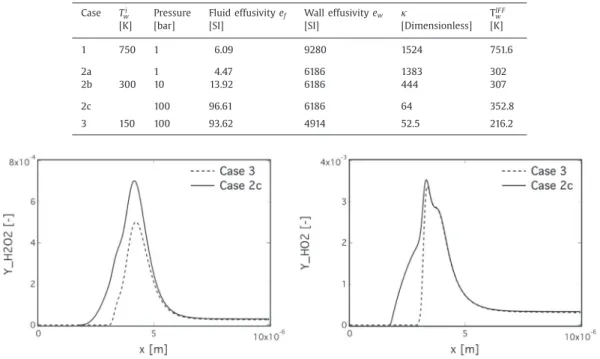
3 150 100 93 .62 4914 52.5 216.2
Fig. 4. Comparison of H 2 O 2 (left) and HO 2 (right) profiles in free propagating flames between Case 2c (solid line) and Case 3 (dashed line).
Flameproperties,computedwiththeBoivinscheme,areshown inTable4forthevariouscases,togetherwiththemeshresolution. The temperature difference Tb
− Tu and flame thickness change largely whenthepressure increases,from2770Kand223
µ
m forCase 2a to 3430K and1.18
µ
m for Case2c. The flame thicknesshasadirectconsequenceonthemeshcellsizethatischanged ac-cordinglytoresolvetheflamefront.
The flame speed first increases with pressure, until ∼15bar, where it reaches ∼12.5m s−1, before decreasing for higher
pres-sure, to reach ∼9.0m s−1. This non-monotonic behavior was
al-ready shownin[31]andisduetothechangeofchain-branching tostraight-chainkinetics.Theflamespeedalsoincreaseswiththe freshgas temperatureTu,whichhasa directeffecton the chem-istrybutalsomodifiesthethermaldiffusivityDu
th=
λ
u/ρ
uC pu. In-creasingthefreshgastemperatureatambientpressureleadstoa strongincreaseoftheflamevelocityandmoderatechangeofburnt gastemperatureandflamethickness(Case1).Finallythecryogenic condition (Case 3)givesa hotbutslowflame.Its structureis de-tailedbelow.6.1. Cryogenicpremixedflame
The cryogenic, supercritical flame (Case 3) exhibits a particu-lar structure.When compared to Case 2c, thefirst impact ofthe lowertemperature,amplifiedbytherealgasthermodynamics,isto significantly increase thedensityinthe freshgas,from48kgm−3
(Case2c)to108kgm−3 (Case3),whiletheburntgastemperature
isonlyslightlylower.Theimportantdecreaseofthelaminarflame speedis mostlyrelatedtothe decreaseofthe thermaldiffusivity
Du
th,from9.2610−7m
2s−1inCase2cto2.2310−7m2s−1inCase3,
associatedto supercriticaltransport properties.The most remark-ablefeatureofCase3isthechangeofthechemicalstructureinthe inductionzoneaheadoftheflame.Figure 4showsHO2 andH2O2
massfraction profilesfor Cases2c and3.As alreadyobserved in manystudies[6,7,12],premixedflamesarecharacterizedby chem-ical reactions occurring in the induction zone between reactants and radical species that diffuse from the main reaction zone. In thecaseofH2/O2flames,thesereactionsleadtotheformationof
HO2 andH2O2intheinductionzone.InCase3,realgastransport
strongly limits radical diffusion, so that even zero-activation, re-combinationreactionssuchasR4,R8orR9ofTable1cannotoccur. As aconsequence,radical speciesdo notappear inthe induction zoneinCase3,asclearlyvisibleinFig.4.Cryogenic,supercritical flamesthereforehavenoreactiveinductionzoneandallreactions start simultaneously when thetemperature reachesa sufficiently highvalue. Thiswillhavedirect consequenceson theflame–wall interactionfortheseflames.
Table 5 summarizesthe fluid andwall effusivities for all test cases.Bothquantitiesincrease withtemperature, butef increases evenmorestronglywithpressure.Theresultinginterface temper-atures predicted by the IFF model, where the wall temperature has been taken to the initial wall temperature Ti
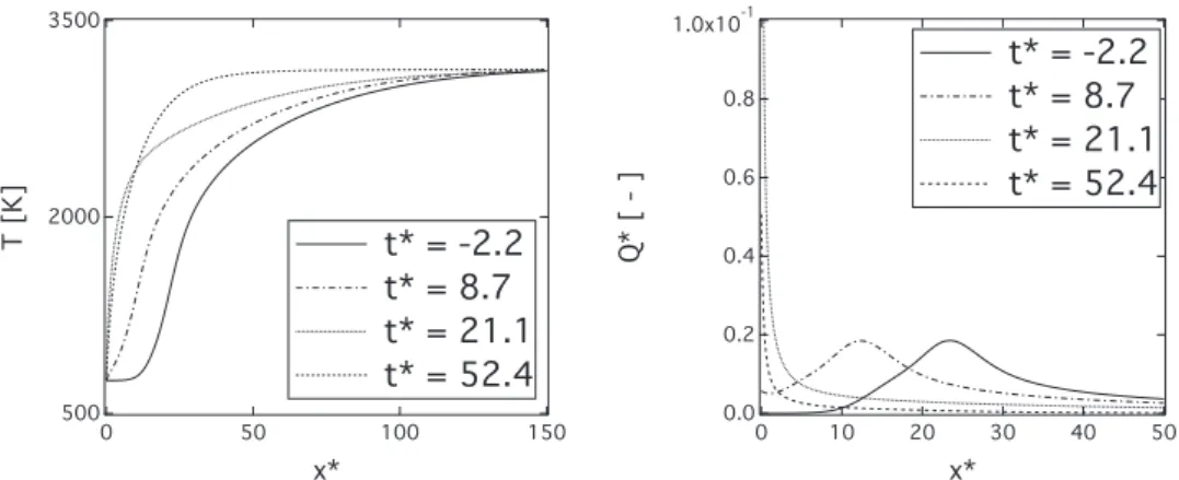
Fig. 5. Profiles of temperature (left) and dimensionless heat release rate (right) at various instants of FWI. Maximum non-dimensional heat release rate is 0.352. Case 1, coupled.
Fig. 6. Profiles of HO 2 (left) and H 2 O 2 (right) mass fractions at various instants of FWI. Case 1, coupled.
fluid temperature has been taken to the burnt gas temperature
Tb, stays close to the initial interface temperature for high val-ues of
κ
, in Cases 1 and 2a. As the fluid thermal effusivity in-creases from Cases 2a to 2c, the ratioκ
decreases and the final walltemperaturemovesawayfromtheinitialtemperature.Finally Cases 2cand 3,withlowκ
, show a significantwall temperature increase.7. Resultsanddiscussion
7.1. Validationcase1
Case1isfirstpresentedforvalidationpurposes,asitiscloseto theisothermalwallcasestudiedinpreviouspublications[7,10,12]. Indeed in this case the high effusivity ratio
κ
=1524 leads to a theoretical wall temperatureTIFFw =751.6K,very closetothe ini-tial wall temperature, so that the isothermal wall assumption is fullyvalid,andnostrongdifferenceswiththecoupledsolutionare expected. Figure5(left)showsthetemperatureprofilesatseveral instants,illustratingthetime-dependencyofFWIandthe quench-ingprocess.Toallowcomparisonbetweencases,timeissetto0at thestartofFWI,i.e.,whenthewallheatfluxstartstoincrease.As a consequencetheflame firstpropagates freely towardsthe wall, keepingafree flamestructure untilt∗ ∼ 0.Then theflame starts
to interactwith the wall, and becomes thinner while approach-ing thewall until t∗ ∼ 20. Atthis time,there isno sufficient
re-mainingfuelinthecoldgasandtheflamequenches.Inthesame time, a transient process occurs fromthe start of FWI, where a verylargeincreaseoftheheatreleaserateatthewallisobserved (Fig.5(right)).Thisislinkedtoachangeofthechemicalbehavior oftheinductionzonewhenapproachingthewall.Infreely
propa-gating flames,preliminarydecompositionofthefueloccursinthe inductionzonethroughhigh-energy-activationreactionswith rad-icals suchasR2andR3(Table1).DuringFWI,thetemperaturein the induction zone decreases down to the wall temperature and these reactions get frozen, leading to a longer persistence of O2
than H2 near thewall. At the same time, andfor the same
rea-son, zero-activation-energy, exothermic,radical recombination re-actions suchasR4andR8becomedominant, andlead tothe ob-servedpeakofheatreleaserateandproductionrateofHO2(Fig.6
(left)).Hence,throughthelow-activation-energy,propagation reac-tionR10hydrogenperoxide(H2O2)isalsoproduced(Fig.6(right)).
All thesechemicalmechanisms werealreadyobservedin isother-malFWI[7,10,12].Byincreasingthewalltemperaturegradient,this strongpeakofheatreleaseatthewallhasadirectimpactonthe wall heat flux. Inaddition, it leads to a zero quenching distance which can thereforenot be used to evaluate the heat flux as in
Eq.(11).
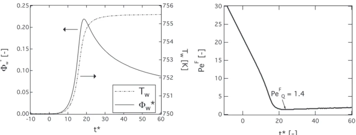
Figure 7 (left) showsthe time evolution ofthe wall heat flux and walltemperature duringFWI.The wall temperature progres-sively increasesto avalueof755.5K,i.e.,slightlyhigherthan the IFF model value of 751.6K. The maximum wall heat flux is ob-tained when theflame quenchesatt∗ ∼ 18,andreaches
8
w,Q=18.9MW m−2 (
8
∗w,Q=0.218).Afterflamequenching,thewallheat fluxexperiencesfirstafastdecrease,thenamuchslowerdecrease (∝1/√t∗) corresponding to theheat diffusion inthe fluid andin the solid.DuringFWI,theflamepropagates towardthewalluntil the remaining fuel is toolow to sustain the flame and compen-sate for thewall heat loss. Thefuel quenchingdistance is there-foremainlycontrolled bytheflamepowerandthewall tempera-ture. Inthe present case, thefuel Peclet numberatquenchingis found PeF
Fig. 7. Temporal evolution of (left) wall heat flux and wall temperature and (right) fuel Peclet number. Case 1, coupled.
Fig. 8. Time evolution of temperature profiles in the solid wall T S . Case 1, coupled.
evolution of the fuel Peclet number during FWI. Both the non-dimensionalfluxandthequenchingfuelPecletnumberaresmaller than usualvaluesobtainedinFWI(∼ 0.3and∼ 3.0respectively) andmaybeexplainedbythehighwalltemperature.Thedecrease of themaximumwall heat fluxwithincreasing wall temperature was alsodescribed in[3].Thismaybe enhancedby thehigh dif-fusivityofH2 andthehighheatreleaseatthewallduetoradical
recombinationasalreadymentioned.Thistrendandthevaluesof the wallheat fluxandquenchingdistanceobtainedinCase1are ingoodagreementwiththeresultsof[7,12]or[10]wherea max-imumwallheatflux∼18MWm−2 wasfoundforthesamecase.
Finally,Fig.8showsthetemporalevolutionofthetemperature inthesolid wall.Onecanobservethat thecouplingmethodology is able to transfer the heat flux to the wall, whichthen diffuses inthesolid.Notethattheheatpenetrationismuchslowerinthe solid than inthe fluid, which isconsistent with thehigher solid effusivity.
7.2. Effectofpressure
InthissectiontheeffectofpressureonFWIisinvestigatedwith Cases2a(1bar)to2c(100bar).AlthoughCase2cisathigh pres-sure,therelativelyhightemperatureleadstoacompressibility fac-torcloseto1andnorealgaseffectsareexpectedhere.Fromthe above IFFanalysis, resultsareexpectedtobecomparabletothose obtainedinFWI withan isothermalwall forCases 2aand2b. In-deed,theIFFinterfacetemperaturedoesnotexceedtheinitialwall temperature by more than 2K and 7K, respectively. In Case 2c however, theburnt gaseffusivity ef=96.6Wm−2K−1s−1/2 being
much higher,the predictedinterface temperatureincreasesup to
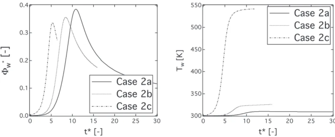
Fig. 9. Temporal evolution of the non-dimensional maximum heat release at the wall for Cases 2a, 2b and 2c, coupled. For all cases, time is set to 0 at the start of FWI.
TIFF
w =352Kandthecoupledsimulationisexpectedtogive signif-icantlydifferentresultsfromthecorrespondingisothermalFWI.
Overall, similar trends as in the validation caseare observed, withaheatreleasepeakandproductionofH2O2 andHO2radicals
occurringatthe wall duringthe FWI.However, asthe wall tem-peratureissmaller,theeffectissignificantlyamplifiedin compari-sontoCase1.Indeedthenon-dimensionalmaximumheatrelease, showninFig.9isabout2ordersofmagnitudelargerduringFWI thaninthe freeflame inCase2a,whereas itwas onlyone order ofmagnitude larger inCase 1 (Fig. 5 (right)).The effectis how-everdecreasingwithpressure,comingbackinCase2ctothesame orderofmagnitudethaninCase1.
Figure10showsthetemporalevolutionofthenon-dimensional heat flux and the temperature at the wall for the three cases. Duetofasterchemistryandsmallerflamethickness, FWIisfaster athighpressure. The maximum wall heat flux isobtained when flame quenches at t∗ ∼ 11, t∗ ∼ 8 and t∗ ∼ 5 for Cases 2a, 2b
and 2c respectively, and slightly decreases with pressure, from
8
∗w,Q=0.388forCase2ato
8
∗w,Q=0.333forCase2c,consistently withthe lower wall heat release effectat highpressure. Overall, themaximumwallheatfluxislittlesensitivetopressureandstays inthe range0.3–0.4,i.e., similar tohydrocarbonflames withlow wall temperatures [4,32,33]. Note however that the dimensional wallheatflux increaseswithpressure,from8
w,Q=26.4MWm−2 forCase 2ato8
w,Q=2.09GWm−2 for Case2c, i.e., reaching ex-tremelyhighvalues.AsexpectedfromtheIFFmodel,theinterface temperature in-creasesonlyslightlyatlowpressure(Cases2aand2b),butreaches amuchhighervalue of545KforthehighpressureCase2c. Note
Fig. 10. Temporal evolution of non-dimensional wall heat flux (left) and wall temperature (right). Cases 2a, 2b, 2c, coupled.
Fig. 11. Time evolution of wall heat flux difference 18w = 8Uw −8Cw between
isothermal wall condition and coupled computation. Case 2c. 8C
w = 2 . 09 e 9 W m −2 .
that the increase is always stronger than predicted by the IFF model. This difference is dueto the strong heat release, both in theflameandatthewall,duringFWIinthe coupledsimulations andwhichisnottakenintoaccountintheIFFmodel.Thismakes theheatfluxstrongerandincreasestheinterfacetemperature.This justifies a posteriori the use of fully coupled simulations for the predictionofheattransfer.
The interface temperatureincreasealso explainsthewall heat flux decreasewithpressure.Figure11showstheevolutionofthe difference betweenthe wall heat flux obtainedin the uncoupled (calculated withan isothermal wall condition atTw=300K)
8
U w andthecoupledcomputation8
CwofCase2c.Themaximum differ-enceisobservedjustbeforequenching,wheretheisothermalwall assumption leads to an overestimationof the maximal wall heat fluxby 200MWm−2,i.e., approximately10% ofthewall heatflux
inthecoupledcase,whichissignificantforthethermalfatigueof solid materials. Thiscorresponds toa non-dimensional wall heat fluxof
8
U∗w,Q=0.352,i.e.,closertothelowpressurecasesthanthe coupledcase.
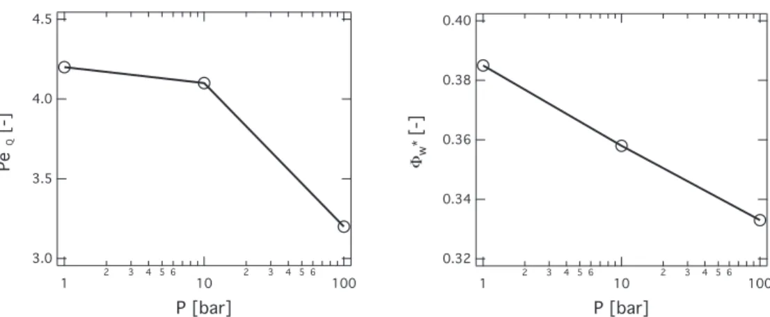
Figure 12 (left) shows the fuel Peclet number obtained at
quenchingforthethreecases.ThequenchingdistanceofPeF Q=4.1 forCase 2a islarger than forCase 1dueto the lower wall tem-perature. It is slightly larger than the value of ∼ 3 typically ob-served inpreviousnumericalandexperimentalstudiesfor hydro-carbonsfuels[4,32,33],whichmaybeduetothehighdiffusivityof
H2. When pressureincreases,the quenchingdistance slightly
de-creases, down to PeF
Q=3.2 forCase 2c, still stayingin the range 3− 4.The slightdecrease ofPeF
Q withpressure maybe again at-tributed to the increase of the interface temperature which al-lows fuel oxidation reactions to occur closer to the wall. As al-ready mentioned, the non-dimensional maximum wall heat flux, also reportedin Fig.12 (right), decreases withpressure. This be-haviorwasalreadyobservedinotherstudies[5,34]forlower pres-sureranges(0.5–3.5bar)andisconfirmedhereforhigherpressure levelsandconjugateheattransfer.Thisalsodemonstratesthat, al-though thesimpleexpressionEq.(11)stillholdsintermsoforder ofmagnitude,itisnotabletodescribeacomplexbehaviorsuchas the simultaneous decreaseofboth
8
∗w,Q andPeFQ withincreasing pressure. Thisindeedistheresultofchemical phenomena occur-ingatthewallandcannotbepredictedfromfreeflameparameters suchastheflamethickness
δ
l.7.3. Supercriticalcase
This section presentsthe resultsobtainedforthe supercritical case (Case 3)where thefreshgas temperaturehasbeen lowered downtoTu
=150K.Thecompressibilityfactorinthatcaseis0.887 meaning that real gas effects have to be taken into account. As shown inTable5, theeffusivity ofthe burntgas islarge insuch thermodynamic conditions,thus requiring the fluid/solidthermal coupling tosimulatethe transientFWI andpredictthe final wall temperature. FWIwithanisothermalwallat150Kleads tostrong watercondensationwhenthecombustionproductsreachthewall, so that direct comparison of coupled or uncoupled cases is not possibleinthiscase.
Figure13(left)reportsthetemperatureprofilesduringFWI.The overall process is similar toall previous casesandis comparable to Case2c,alsoathighpressure.AsinCase2c, theinteractionis quite fast,with quenching occurring att∗ ∼ 8, andheat release
peakonthewallisstillobserved(Fig.13(right)).Howeveraswas observedinthecryogenicfreeflame,theinductionzoneisfrozen due tothe low temperatureanddoesnot interactwith thewall. Neither H2O2 orHO2 arepresentoutsidetheflamezoneandthey
start to build on thewall only whenthe flamereaches thewall. Compared to Case 2c, the increase of heat release atthe wall is delayedandstartsshortlybefore quenching.Asa result,although theincreaseiscomparabletoCase2c,its impactonthewallheat fluxisreduced.
In supercritical conditions, the fluid properties differ largely fromtheperfectgas,withathermaldiffusivitydividedby4when compared toCase2c. (Case2c:
λ
u/ρ
uC pu=9.2610−7m2s−1 and
Case 3 :
λ
u/ρ
uCup=2.2310−7m2s−1). This, combined with the low fresh gas temperature, leads to a large quenching distance
Fig. 12. Effect of pressure on the quenching fuel Peclet number Pe F
Q ( ◦) (left) and on the dimensionless maximum wall heat flux 8∗w,Q ( ◦) (right) for Cases 2a,b,c, coupled
simulations.
Fig. 13. Profiles of temperature at various instants of FWI (left) and time evolution of the maximum heat release at the wall (right). Case 3, coupled.
Fig. 14. Temporal evolution of wall heat flux and wall temperature. Case 3, coupled.
corresponding toPeF
Q=6.0.As a consequence,the wall tempera-tureincreasesslowly,remaininglowduringthequenchingprocess and still increasing after the flamehas extinguished (Fig. 14). As theheatreleaseatthewallstayszeroforalongtimeandstartsto increasejustbeforequenching,itdoesnotcontributemuchtothe wall temperatureincrease which stays closeto the predictedIFF temperature(TIFF
w =216.2K).Thenon-dimensionalmaximumwall heat fluxreachesavalue of0.36(
8
w,Q=1.97GWm−2), i.e.,stays in therange0.3–0.4, mainlythanks to thelarge temperature dif-ference Tb− Tu.Inthiscase,Eq.(11)doesnotholdanymore. Thisagaindemonstratesthatthequenchingdistanceandthemaximum wall heatflux arenot directlylinked butstrongly dependon the interfacetemperature,requiringtheuseofcoupledsimulations.
8. Conclusions
The interaction between premixed flames and non-adiabatic wallshasbeeninvestigatedinaconjugateheattransferapproach, where the fluid and the solid wall are thermally coupled. To be representative of liquid rocket engines, stoichiometric H2–O2
mixtures in ambient andcryogenic (low temperature, high pres-sure)conditionshavebeenconsidered.Aunique framework, cou-pling both fluid and heat transfer solvers, was used in order to take into account the wall heating transient phenomena. It was demonstratedthatiftheeffusivityoftheburntgasbecomes non-negligible comparedto that of the solid, theisothermal assump-tiondoesnotholdanymore.Itwasfoundthatthissituationmainly occurs at high pressure, requiring the use of fluid–solid ther-mal coupling. When pressure increases, the more powerful and much thinner flame leads to important quenching distance de-crease and maximum wall heat flux increase by two orders of magnitude compared to atmospheric conditions. However, when non-dimensionalized with the flame thickness and flame power, both quantities become almost insensitive to pressure and take typicalvaluesalreadyobservedinhydrocarbonflames.Still,the in-creaseofwalltemperatureduetoconjugateheattransfer,andthe heatreleaseatthewallduetoradicalrecombination,are responsi-bleforaslightdecreaseofthequenchingdistanceandmaximum wall heat flux when pressure increases.Finally, low-temperature, high-pressurecryogenicconditionswhichleadtosupercriticalfluid properties and the vanishing of the induction zone, give a very
largequenchingdistance.Howeverthenon-dimensionalmaximum wallheatfluxstays comparabletothepreviouscases.Inthiscase also,significant impactofthe conjugateheattransfer isobserved and requires fluid–solid thermal coupling to describe accurately thewall temperatureandtheflamebehavior. Thesefindingsmay haveimportantimplicationsforflamestabilizationandthermal fa-tigue in practical systems such as liquid rocket engine injectors. The demonstrated feasibility and relevance of thermally coupled fluid–solidsimulationsallowstoremovetheuncertaintyaboutthe wallthermalconditionsandimprovethepredictionanddesignof optimumburnergeometries.
Supplementarymaterial
Supplementary material associated with this article can be found, in the online version, at 10.1016/j.combustflame.2016.01. 004.
References
[1] G. Bruneaux , T. Poinsot , J.H. Ferziger , Premixed flame–wall interaction in a tur- bulent channel flow: budget for the flame surface density evolution equation and modelling, J. Fluid Mech. 349 (1997) 191–219 .
[2] T. Poinsot , D. Haworth , G. Bruneaux , Direct simulation and modelling of flame–wall interaction for premixed turbulent combustion, Combust. Flame 95 (1/2) (1993) 118–133 .
[3] O.A. Ezekoye , R. Greif , D. Lee , Increased surface temperatureeffects on wall heat transfer during unsteady flame quenching, Symp. (Int.) Combust. 24 (1) (1992) 1465–1472 .
[4] J.H. Lu , O. Ezekoye , R. Greif , F. Sawyer , Unsteady heat transfer during side wall quenching of a laminar flame, Symp. (Int.) Combust. 23 (1) (1990) 4 41–4 46 . [5] B. Boust , J. Sotton , S. Labuda , M. Bellenoue , A thermal formulation for sin-
gle-wall quenching of transient laminar flames, Combust. Flame 149 (3) (2007) 286–294 .
[6] C.K. Westbrook , A .A . Adamczyk , G.A . Lavoie , A numerical study of laminar flame wall quenching., Combust. Flame 40 (1981) 81–99 .
[7] F. Dabireau , B. Cuenot , O. Vermorel , T. Poinsot , Interaction of H 2 /O 2 flames with
inert walls, Combust. Flame 135 (1–2) (2003) 123–133 .
[8] A. Delataillade , F. Dabireau , B. Cuenot , T. Poinsot , Flame/wall interaction and maximum heat wall fluxes in diffusion burners, Proc. Combust. Inst. 29 (2002) 775–780 .
[9] P. Popp , M. Baum , An analysis of wall heat fluxes, reaction mechanisms and unburnt hydrocarbons during the head-on quenching of a laminar methane flame, Combust. Flame 108 (3) (1997) 327–348 .
[10] R. Owston , V. Magi , J. Abraham , Interactions of hydrogens flames with walls: influence of wall temperature, pressure, equivalence ratio and diluents, Int. J. Hydrogen Energy 32 (2007) 2094–2104 .
[11] T.K. Kim , D.H. Lee , S. Kwon , Effects of thermal and chemical surface–flame in- teraction on flame quenching, Combust. Flame 146 (2006) 19–28 .
[12] A. Gruber , R. Sankaran , E.R. Hawkes , J. Chen , Turbulent flame–wall interaction: a direct numerical simulation study, J. Fluid Mech. 658 (2010) 5–32 .
[13] F. Duchaine , A. Corpron , L. Pons , V. Moureau , F. Nicoud , T. Poinsot , Develop- ment and assessment of a coupled strategy for conjugate heat transfer with large eddy simulation: application to a cooled turbine blade, Int. J. Heat Fluid Flow 30 (6) (2009) 1129–1141 .
[14] L. Quartapelle , V. et Selmin , High-order Taylor-Galerkin methods for nonlinear multidimensional problems, Finite Elements in Fluids 76 (90) (1993) 46 . [15] O. Colin , M. Rudgyard , Development of high-order Taylor–Galerkin schemes for
LES, J. Comput. Phys. 162 (2) (20 0 0) 338–371 .
[16] S. Buis , A. Piacentini , D. Déclat , PALM: a computational framework for as- sembling high performance computing applications, Concurr. Comput. 18 (2) (2005) 231–245 .
[17] F. Duchaine , S. Mendez , F. Nicoud , A. Corpron , V. Moureau , T. Poinsot , Conju- gate heat transfer with large eddy simulation application to gas turbine com- ponents, Comptes Rendus Acad. Sci. Mécanique 337 (6-7) (2009) 550–561 . [18] T. Poinsot , T. Echekki , M.G. Mungal , A study of the laminar flame tip and im-
plications for premixed turbulent combustion, Combust. Sci. Technol. 81 (1-3) (1992) 45–73 .
[19] P. Boivin , C. Jiménez , A. Sanchez , F. Williams , An explicit reduced mechanism for H 2 –air combustion, Proc. Combust. Inst. 33 (1) (2011) 517–523 .
[20] P. Saxena , F. Williams , Testing a small detailed chemical-kinetic mechanism for the combustion of hydrogen and carbon monoxide., Combust. Flame 145 (2006) 316–323 .
[21] A . Sanchez , F.A . Williams , Recent advances in understanding of flammability characteristics of hydrogen, Prog. Energy Combust. Sci. 41 (2013) 1–55 . [22] D.G. Goodwin , CANTERA: An open-source, object-oriented software suite for
combustion, NSF Workshop on Cyber-based Combustion Science, National Sci- ence Foundation, NSF Headquarters, Arlington, VA (2006) .
[23] D.Y. Peng , D.B. Robinson , A new two-constant equation of state, Ind. Eng. Chem. Fundam. 15 (1) (1976) 59–64 .
[24] B.E. Poling , J.M. Prausnitz , J.P. O’Connell , The properties of gases and liquids, 5th ed., McGraw-Hill, 2001 .
[25] T.-H. Chung , L.L. Lee , K.E. Starling , Application of kinetic gas theories and mul- tiparameter correlation for prediction of dilute gas viscosity and thermal con- ductivity, Ind. Eng. Chem. Fundam. 23 (1984) 8–13 .
[26] V. Giovangigli , L. Matuszewski , F. Dupoirieux , Detailed modeling of planar tran- scritical H 2 -O 2 –N 2 flames, Combust. Theory Model. 15 (2) (2011) 141–182 .
[27] A. Ruiz , L. Selle , Simulation of a turbulent supercritical hydrogen/oxygen flow behind a splitter plate: cold flow and flame stabilization, Seventh Mediter- ranean Combustion Symposium (2011) .
[28] T. Schmitt , L. Selle , A. Ruiz , B. Cuenot , Large-eddy simulation of supercritical– pressure round jets, AIAA J. 48 (9) (2010) 2133–2144 .
[29] J. Warnatz , Concentration-, pressure-, and temperature-dependence of the flame velocity in hydrogen-oxygen-nitrogen mixtures, Combust. Sci. Technol. 26 (1981) 203–213 .
[30] E. Lemmon , M. Huber , M. McLinden , NIST standard reference database 23: ref- erence fluid thermodynamic and transport properties-REFPROP, Version 8.0, Technical Report, National Institute of Standards and Technology, Standard Ref- erence Data Program, Gaithersburg, MD, 2007 .
[31] M. Kuznetsov , R. Redlinger , W. Breitung , J. Grune , A. Friedrich , N. Ichikawa , Laminar burning velocities of hydrogen–oxygen-steam mixtures at elevated temperatures and pressures, Proc. Combust. Inst. 33 (2011) 895–903 . [32] W.M. Huang , S.R. Vosen , R. Greif , Heat transfer during laminar flame quench-
ing, effect of fuels, Symp. (Int.) Combust. 21 (1) (1986) 1853–1860 .
[33] S.R. Vosen , R. Greif , C.K. Westbrook , Unsteady heat transfer during laminar flame quenching., Symp. (Int.) Combust. 20 (1) (1984) 76–83 .
[34] J. Sotton , B. Boust , S. Labuda , M. Bellenoue , Head-on quenching of transient laminar flame: heat flux and quenching distance measurements, Combust. Sci. Technol. 177 (7) (2005) 1305–1322 .
![Fig. 2. 1D flame profiles of (a) temperature T , (b) heat release rate Q , (c) HO 2 and (d) H mass fractions for (–) San Diego [20] and (- -) Boivin [19] mechanisms](https://thumb-eu.123doks.com/thumbv2/123doknet/3125330.88872/4.892.154.759.119.589/flame-profiles-temperature-release-fractions-diego-boivin-mechanisms.webp)
![Fig. 3. 1D flame profiles of (a) temperature T , (b) heat release rate Q , (c) HO 2 and (d) H mass fractions for (–) San Diego [20] and (- -) Boivin [19] mechanisms](https://thumb-eu.123doks.com/thumbv2/123doknet/3125330.88872/5.892.139.742.119.587/flame-profiles-temperature-release-fractions-diego-boivin-mechanisms.webp)